EP0480321B1 - Wagon de transport de déblais - Google Patents
Wagon de transport de déblais Download PDFInfo
- Publication number
- EP0480321B1 EP0480321B1 EP91116935A EP91116935A EP0480321B1 EP 0480321 B1 EP0480321 B1 EP 0480321B1 EP 91116935 A EP91116935 A EP 91116935A EP 91116935 A EP91116935 A EP 91116935A EP 0480321 B1 EP0480321 B1 EP 0480321B1
- Authority
- EP
- European Patent Office
- Prior art keywords
- box
- conveyor belt
- waste material
- discharge conveyor
- railway wagon
- Prior art date
- Legal status (The legal status is an assumption and is not a legal conclusion. Google has not performed a legal analysis and makes no representation as to the accuracy of the status listed.)
- Expired - Lifetime
Links
Images

Classifications
-
- E—FIXED CONSTRUCTIONS
- E01—CONSTRUCTION OF ROADS, RAILWAYS, OR BRIDGES
- E01B—PERMANENT WAY; PERMANENT-WAY TOOLS; MACHINES FOR MAKING RAILWAYS OF ALL KINDS
- E01B27/00—Placing, renewing, working, cleaning, or taking-up the ballast, with or without concurrent work on the track; Devices therefor; Packing sleepers
- E01B27/02—Placing the ballast; Making ballastway; Redistributing ballasting material; Machines or devices therefor; Levelling means
-
- E—FIXED CONSTRUCTIONS
- E01—CONSTRUCTION OF ROADS, RAILWAYS, OR BRIDGES
- E01B—PERMANENT WAY; PERMANENT-WAY TOOLS; MACHINES FOR MAKING RAILWAYS OF ALL KINDS
- E01B2203/00—Devices for working the railway-superstructure
- E01B2203/03—Displacing or storing ballast
- E01B2203/032—Displacing or storing ballast with special use or configuration of conveyor belts
-
- E—FIXED CONSTRUCTIONS
- E01—CONSTRUCTION OF ROADS, RAILWAYS, OR BRIDGES
- E01B—PERMANENT WAY; PERMANENT-WAY TOOLS; MACHINES FOR MAKING RAILWAYS OF ALL KINDS
- E01B2203/00—Devices for working the railway-superstructure
- E01B2203/03—Displacing or storing ballast
- E01B2203/034—Displacing or storing ballast using storing containers
Definitions
- the present invention relates to a railroad car for the transport of overburden, according to the preamble of claim 1.
- railway wagons usually consist of two different parts: the first forms the organs for the movement of the wagon, d.s. the multitude of pairs of wheels running on rails; the second, on the other hand, consists of a "box" with high side walls that is open at the top and sits on a lower frame.
- This box forms the container for the overburden that is poured in from above by the excavator machines.
- a train in the working zone consisting of a series of such wagons which, after loading of the overburden has been loaded, are driven into an area that has been specially prepared for unloading the overburden.
- the railroad cars are usually provided with a series of telescopic arms, each operated by pneumatic pistons inserted between the lower frame and the "box".
- the operator actuates the pistons mentioned, which enable the box to be tilted to one side, so that the waste material can be emptied on one side thereof and deposited on the underlying floor.
- the object of the present invention is therefore to avoid the above-mentioned inadequacies by creating a railroad car for the transport of overburden, which is cheap and is provided with a combination of elements in its interior, which also rationally, quickly and conveniently load / unload the overburden allow previously unprepared soil.
- One of the advantages achieved with the present invention consists in the provision of a series of conveyor belts which ensure the rapid and efficient transport of the overburden brought into the box;
- the second movable and rotatable conveyor belt enables the overburden to be unloaded outside the railroad car, so that preparatory work with scraping buckets can be omitted.
- the railway car in question consists of a double pair of wheels 1, which can be moved on rails 21 and are connected by a horizontal flat bottom 2, on which an open-top box 3 is seated, which serves to receive the overburden, which in its entirety also includes 4 is designated.
- the box for receiving the overburden 4 is defined by a fixed structure consisting of the walls 3, a plurality of lids 7 to be opened and a closure bottom formed by the horizontal emptying belt 9.
- the conveyor belt 5 is arranged centrally and in the longitudinal direction on top of the box 3 and has an extension which is greater than the total length of the box.
- FIG. 1 shows that the two ends of the conveyor belt 5, each running around drums 5t, partially protrude from the box 3.
- a wedge-shaped element 6 Arranged above this conveyor belt 5 is a wedge-shaped element 6, which serves to displace the overburden 6 passing on the conveyor belt 5 and is horizontally movable over the entire longitudinal extent of the box 3 by means of slide devices 11.
- This wedge-shaped element 6 consists of a pair of opposing blades 6a and 6b, which form a wedge in plan.
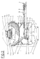
- Said slide devices 11 consist of a pair of arms 11a and 11b (see FIG. 2) which form a frame which comprises the wedge-shaped element 6 on two sides and which are attached at one end to the articulated parallelogram 13 and, moreover, with small wheels at the other end 14a and 14b are provided, which on a pair of horizontal rails 15 run, which form part of the support frame of the conveyor belt 5 or alternatively can be provided at the upper end of the box 3 and which are arranged on opposite sides to the conveyor belt 5 and extend over the entire length of the box 3.
- the plurality of lids 7 are arranged in pairs opposite to each other and together with the end part of the box 3 form a corresponding row of funnel-shaped module units for receiving the overburden 4.
- These covers 7 can be moved by means of corresponding movement devices 12 between an extreme closed position of the module unit, in which each cover 7 is in contact with the end part of the box 3 without dissolving the continuity, and an open position of the module unit, in which each cover 7 is in one from the end part of the box 3 is located and consequently allows the inflow of overburden 4 over said end part of the box 3 also.
- the movement devices 12 consist of a hydraulic piston 16 for each of the existing covers 7, the ends of which are articulated on the inner part of the flat bottom 2 or on the cover 7.
- This emptying belt 9 can be pivoted about its own axis by means of movement devices 10 ⁇ which consist of a motor-driven turntable 17 which moves the aforementioned end (visible in FIG. 2) by an arc of approximately 180 ⁇ °.
- the turntable 17 swivels the discharge belt 9 between an inoperative position, in which the emptying belt 9 is arranged parallel to the flat bottom 2, and an unloading operating position for the waste material 4, in which the emptying belt 9 is arranged transversely and projecting to the flat bottom 2.
- the discharge belt 9 is protected by a trough frame 18 which completely encloses it, except, of course, the end of the discharge belt 9, which is intended for unloading the waste material 4 onto the underlying floor.
- the aforementioned devices for the movement 30 ⁇ and positioning 31 are - as can be seen well from FIGS. 1 and 2 - arranged below the box 3 and parallel to it over its entire length, in order gradually to act as the pivot point of the discharge belt 9 in the end Bring the area of the upper lid 7 located in the extreme open position.
- these devices for the movement 30 ⁇ and positioning 31 consist of a support carriage 32 for the emptying belt 9, which is inserted between the flat bottom 2 and the end of the emptying belt 9 which acts as a fulcrum and has on both sides a number of small wheels 33, which are in a pair run from mutually parallel guides 34 which are fastened on the flat floor 2 and extend over the entire length of the railroad car.
- the support carriage 32 is connected on both sides to an endless chain 35 which, for example, runs around sprockets (not shown here), which are provided at the relevant ends of the railway carriage, and is driven by means of a reduction gear 40 ⁇ which is arranged on the support carriage 32 to allow the displacement and positioning of the emptying belt 9 in the area of the cover 7, little by little as they open.
- the support carriage 32 can moreover be provided with path end devices which enable the support carriage to be stopped exactly in the region of the upper cover 7, which is in the extreme open position.
- the railway wagon designed in this way works in the following manner, assuming that a set of several railway wagons stands for loading the overburden in the loading zone: the machines provided for loading the overburden put it on the conveyor belt 5 of the first wagon and it is transported along the same.
- the wedge-shaped element 6 is arranged in a raised position by means of the articulated parallelogram 13, so that the waste material 4 can pass through to the last car.
- the wedge-shaped element 6 is in the position approximated to the conveyor belt 5 and in the region of the closing end of the box 3, in order in this way to cause the waste material 4 to fall down into the funnel-shaped module unit located underneath.
- the wedge-shaped element 6 is pushed forward in the direction C opposite to the direction of movement of the conveyor belt 5 (see arrows in FIG. 1), so that the inflow of waste material 4 into this last module unit is interrupted and with the filling in relation to the direction of movement of the overburden 4 in front of the module unit is started.
- the wedge-shaped element 6 of the following car is actuated, which begins with the filling phase of its module units as described above.
- the emptying belt 9 is pivoted by approximately 90 ° for each wagon, so that it is arranged on the side of the railway line on which the waste material 4 is intended to be unloaded.
- the various lids 7 are then opened in individual succession by means of the pistons 13, which allow the waste material 4 to be fed directly onto the emptying belt 9, from which it is then transported to the intended unloading point.
- the emptying belt 9 is brought under the next module by means of the support carriage 32, which in turn is moved by the chain (s) operated by a worker, in order to be able to empty the waste material 4 therefrom.
Landscapes
- Engineering & Computer Science (AREA)
- Architecture (AREA)
- Civil Engineering (AREA)
- Structural Engineering (AREA)
- Arc-Extinguishing Devices That Are Switches (AREA)
- Structure Of Belt Conveyors (AREA)
- Braking Arrangements (AREA)
- Vehicle Cleaning, Maintenance, Repair, Refitting, And Outriggers (AREA)
- Filling Or Emptying Of Bunkers, Hoppers, And Tanks (AREA)
- Train Traffic Observation, Control, And Security (AREA)
Claims (7)
- Wagon de chemin de fer pour le transport de déblais constitué au moins de deux paires de roues (1) roulant sur des rails (21) qui sont reliées par un fond plat (2) sur lequel repose un caisson (3) ouvert en haut prévu pour la réception des déblais (4), caractérisé par- une courroie transporteuse horizontale (5) servant à la réception depuis l'extérieur et au transport des déblais (4), qui est disposée approximativement au centre et dans la direction longitudinale en haut sur le caisson (3), ce caisson (3) étant pourvu en outre d'un élément en forme de coin (6) qui est déplaçable au moyen de dispositifs formant chariots (11) horizontalement sur toute l'étendue longitudinale du caisson (3) et qui est disposé au-dessus et coaxialement à la courroie transporteuse (5), et qui est apte à déplacer des deux côtés et régulièrement les déblais (4) arrivant sur la courroie transporteuse (5) dans l'intérieur du caisson (3) ;- une pluralité de couvercles (7) qui sont disposés par deux opposés l'un à l'autre et au voisinage du fond du caisson (3) pour former avec ce dernier une rangée correspondante d'unités modulaires réalisées en forme de trémie pour la réception des déblais (4) et qui sont déplaçables au moyen de dispositifs de déplacement (12) correspondants entre une position de fermeture extrême de l'unité modulaire dans laquelle les couvercles (7) se trouvent, sans interrompre la continuité, en contact avec le caisson (3), et une position d'ouverture extrême de l'unité modulaire dans laquelle les couvercles (7) se trouvent dans une position décalée du caisson et permettent la sortie des déblais (4) de celui-ci ;- une courroie de vidange horizontale (9) pour les déblais qui est disposée avec le brin actif concerné de façon coplanaire en-dessous des couvercles (7) afin de recevoir les déblais (4) tombant des unités modulaires et pour les transporter et qui peut être déplacée au voisinage de l'une de ses extrémités fonctionnant comme point de pivotement autour d'un axe vertical au moyen de dispositifs de rotation (10) entre une position non opérationnelle dans laquelle la courroie de vidange (9) s'étend sensiblement parallèlement au caisson (3) et une position de vidange opérationnelle pour les déblais (4) dans laquelle la courroie de vidange (9) est disposée relativement au caisson (3) approximativement transversalement et en saillie ;- des dispositifs pour le déplacement (30) et le positionnement (31) qui sont disposés en-dessous du caisson (3) et parallèlement à celui-ci sur toute sa longueur, qui sont aptes à amener l'extrémité fonctionnant comme point de pivotement de la courroie de vidange (9) peu à peu au voisinage du couvercle supérieur (7) dans la position d'ouverture extrême.
- Wagon de chemin de fer selon la revendication 1, caractérisé en ce que l'élément en forme de coin (6) est constitué d'une paire de lames (6a, 6b) qui, vues en plan, forment un coin et qui sont reliées en haut à un parallélogramme articulé (13) qui est fixé de son côté aux dispositifs formant chariots précités (11), et qui permet à l'élément en forme de coin (6) un déplacement en hauteur entre une position de proximité immédiate à la courroie transporteuse (5) et une position d'éloignement extrême de la courroie transporteuse (5).
- Wagon de chemin de fer selon la revendication 1, caractérisé en ce que les dispositifs formant chariot (11) sont constitués d'une paire de bras (lla, llb) qui sont fixés, à une extrémité, à un parallélogramme articulé (13) et qui sont pourvus, à l'autre extrémité, de roues (14a, 14b) qui roulent sur une paire de rails horizontaux (15) dont est pourvue l'extrémité supérieure du caisson (3) et qui sont disposées aux côtés opposés à la courroie transporteuse (5).
- Wagon de chemin de fer selon la revendication 1, caractérisé en ce que les dispositifs de rotation (10) pour le déplacement des couvercles (7) sont constitués, respectivement, de pistons hydrauliques (16) dont chacun est articulé avec ses extrémités à la partie intérieure du fond plat (2) ou au couvercle (7).
- Wagon de chemin de fer selon la revendication 1, caractérisé en ce que les dispositifs de rotation (10) pour le déplacement de la courroie de vidange (9) sont constitués d'une traverse pivotante (17) entraînée par moteur qui est placé entre la courroie de vidange (9), au voisinage de l'extrémité fonctionnant comme point de pivotement, et les dispositifs pour le déplacement (30) et le positionnement (31).
- Wagon de chemin de fer selon la revendication 1, caractérisé en ce que la courroie de vidange (9) est pourvue d'un cadre en auge (18) qui entoure complètement la courroie de vidange (9).
- Wagon de chemin de fer selon la revendication 1, caractérisé en ce que les dispositifs pour le déplacement (30) et le positionnement (31) sont constitués d'un wagon d'appui (32) pour la courroie de vidange (9) qui est placé entre le fond plat (2) et l'extrémité fonctionnant comme point de pivotement de la courroie de vidange (9) et qui possède une série de roues (33) qui roulent dans une paire de guidages parallèles (34) qui sont fixés sur le fond plat (2) et qui s'étendent sur toute la longueur du wagon de chemin de fer, le wagon d'appui (32) étant relié des deux côtés à une chaîne sans fin (35) afin de permettre le déplacement et le positionnement de la courroie de vidange (9) au voisinage des couvercles (7).
Priority Applications (1)
| Application Number | Priority Date | Filing Date | Title |
|---|---|---|---|
| AT91116935T ATE102671T1 (de) | 1990-10-09 | 1991-10-04 | Eisenbahnwagen fuer den transport von abraumgut. |
Applications Claiming Priority (2)
| Application Number | Priority Date | Filing Date | Title |
|---|---|---|---|
| IT00368390A IT1242586B (it) | 1990-10-09 | 1990-10-09 | Carro ferroviario per trasporto detriti. |
| IT368390 | 1990-10-09 |
Publications (2)
| Publication Number | Publication Date |
|---|---|
| EP0480321A1 EP0480321A1 (fr) | 1992-04-15 |
| EP0480321B1 true EP0480321B1 (fr) | 1994-03-09 |
Family
ID=11111370
Family Applications (1)
| Application Number | Title | Priority Date | Filing Date |
|---|---|---|---|
| EP91116935A Expired - Lifetime EP0480321B1 (fr) | 1990-10-09 | 1991-10-04 | Wagon de transport de déblais |
Country Status (5)
| Country | Link |
|---|---|
| EP (1) | EP0480321B1 (fr) |
| AT (1) | ATE102671T1 (fr) |
| DE (1) | DE59101158D1 (fr) |
| ES (1) | ES2050494T3 (fr) |
| IT (1) | IT1242586B (fr) |
Families Citing this family (4)
| Publication number | Priority date | Publication date | Assignee | Title |
|---|---|---|---|---|
| DE102005031413B4 (de) * | 2005-07-04 | 2009-06-25 | Oldenburg, Jörg, Prof. Dr. | Stufenloses Elektrogetriebe |
| EP1775190A3 (fr) * | 2005-10-17 | 2007-06-20 | VolkerRail Nederland BV | Renouvellement du lit de ballast d'une voie ferrée |
| BR112013020831B1 (pt) | 2011-02-15 | 2020-11-24 | Metso Minerals, Inc | Aparelho de processamento movel |
| FR2988737B1 (fr) * | 2012-03-29 | 2018-11-16 | Etf | Train de ballastage double flux. |
Family Cites Families (2)
| Publication number | Priority date | Publication date | Assignee | Title |
|---|---|---|---|---|
| DE2146590A1 (de) * | 1970-09-17 | 1972-03-23 | Rossi, Lionello, Rom | Trichterwagen mit Vorrichtungen zum automatischen Beladen und Entladen |
| DE2403010A1 (de) * | 1974-01-23 | 1975-07-31 | Wieger Maschbau | Vorrichtung zum be- und entladen von aufnahmewagen |
-
1990
- 1990-10-09 IT IT00368390A patent/IT1242586B/it active IP Right Grant
-
1991
- 1991-10-04 ES ES91116935T patent/ES2050494T3/es not_active Expired - Lifetime
- 1991-10-04 EP EP91116935A patent/EP0480321B1/fr not_active Expired - Lifetime
- 1991-10-04 AT AT91116935T patent/ATE102671T1/de not_active IP Right Cessation
- 1991-10-04 DE DE91116935T patent/DE59101158D1/de not_active Expired - Lifetime
Also Published As
| Publication number | Publication date |
|---|---|
| IT9003683A1 (it) | 1992-04-09 |
| ATE102671T1 (de) | 1994-03-15 |
| DE59101158D1 (de) | 1994-04-14 |
| IT9003683A0 (it) | 1990-10-09 |
| IT1242586B (it) | 1994-05-16 |
| EP0480321A1 (fr) | 1992-04-15 |
| ES2050494T3 (es) | 1994-05-16 |
Similar Documents
| Publication | Publication Date | Title |
|---|---|---|
| DE3312492C2 (fr) | ||
| DE68921108T2 (de) | Verfahren und Vorrichtung zum Transport von Materialien. | |
| DE3711707A1 (de) | Gleisverfahrbarer schuettgutverladewagen mit regelbaren entladeschurren | |
| DE69927563T2 (de) | Automatische Waage für Obst und ähnliches | |
| EP0059984B1 (fr) | Dispositif de distribution pour un convoyeur | |
| DE1456715A1 (de) | Eimerkettenfoerderer | |
| DE2109213B2 (de) | Becherförderer für Schüttgut | |
| DE2713634A1 (de) | Fahrbare maschinenanordnung zum transport von schuettgut | |
| CH638848A5 (de) | Selbstfahrbare gleisbett-reinigungsmaschine mit vorrichtungen zum aufnehmen, reinigen, speichern und wiedereinbringen des schotters. | |
| DE1456657B1 (de) | Einrichtung zum Abtragen von Halden | |
| EP0480321B1 (fr) | Wagon de transport de déblais | |
| DE69007216T2 (de) | Eisenbahnwagen für den Transport von Schutt. | |
| DE2628325A1 (de) | Vorrichtung zum beschicken eines fertigers fuer bituminoese belaege | |
| DE69708930T2 (de) | Vorrichtung und verfahren zum leeren eines gefüllten containers | |
| WO1985003279A1 (fr) | Procede et installation pour decharger des marchandises en vrac d'un gros conteneur | |
| DE3136316C2 (de) | Entladevorrichtung, insbesondere zur Aufnahme von Schüttgut aus Waggons od. dgl. | |
| DE4104877A1 (de) | Schuettgutverladewagen | |
| DE3332668C2 (fr) | ||
| DE4213925A1 (de) | Wagenzug fuer den schuettgut-transport | |
| DE68907355T2 (de) | Ausladen der Fracht bei Güterwagen. | |
| DE2846789C2 (de) | Entspeicherungsgerät für das Abräumen von Schüttguthalden | |
| DE3519208A1 (de) | Brueckengeraet fuer das abraeumen von schuettguthalden | |
| DE8320290U1 (de) | Beladevorrichtung für kastenförmige Großbehälter | |
| DE3504587A1 (de) | Umschlaganlage fuer in nach oben offenen kaesten zu lagerndes schuettfaehiges gut | |
| DE3219185C2 (de) | Brückengerät zum Abräumen von Schüttguthalden |
Legal Events
| Date | Code | Title | Description |
|---|---|---|---|
| PUAI | Public reference made under article 153(3) epc to a published international application that has entered the european phase |
Free format text: ORIGINAL CODE: 0009012 |
|
| AK | Designated contracting states |
Kind code of ref document: A1 Designated state(s): AT BE DE ES FR GB NL |
|
| 17P | Request for examination filed |
Effective date: 19920803 |
|
| 17Q | First examination report despatched |
Effective date: 19930318 |
|
| GRAA | (expected) grant |
Free format text: ORIGINAL CODE: 0009210 |
|
| AK | Designated contracting states |
Kind code of ref document: B1 Designated state(s): AT BE DE ES FR GB NL |
|
| REF | Corresponds to: |
Ref document number: 102671 Country of ref document: AT Date of ref document: 19940315 Kind code of ref document: T |
|
| GBT | Gb: translation of ep patent filed (gb section 77(6)(a)/1977) |
Effective date: 19940314 |
|
| REF | Corresponds to: |
Ref document number: 59101158 Country of ref document: DE Date of ref document: 19940414 |
|
| REG | Reference to a national code |
Ref country code: ES Ref legal event code: FG2A Ref document number: 2050494 Country of ref document: ES Kind code of ref document: T3 |
|
| ET | Fr: translation filed | ||
| PLBE | No opposition filed within time limit |
Free format text: ORIGINAL CODE: 0009261 |
|
| STAA | Information on the status of an ep patent application or granted ep patent |
Free format text: STATUS: NO OPPOSITION FILED WITHIN TIME LIMIT |
|
| 26N | No opposition filed | ||
| REG | Reference to a national code |
Ref country code: GB Ref legal event code: IF02 |
|
| PGFP | Annual fee paid to national office [announced via postgrant information from national office to epo] |
Ref country code: AT Payment date: 20060912 Year of fee payment: 16 |
|
| PG25 | Lapsed in a contracting state [announced via postgrant information from national office to epo] |
Ref country code: AT Free format text: LAPSE BECAUSE OF NON-PAYMENT OF DUE FEES Effective date: 20071004 |
|
| PGFP | Annual fee paid to national office [announced via postgrant information from national office to epo] |
Ref country code: GB Payment date: 20090828 Year of fee payment: 19 |
|
| PGFP | Annual fee paid to national office [announced via postgrant information from national office to epo] |
Ref country code: ES Payment date: 20090922 Year of fee payment: 19 |
|
| PGFP | Annual fee paid to national office [announced via postgrant information from national office to epo] |
Ref country code: NL Payment date: 20090930 Year of fee payment: 19 Ref country code: BE Payment date: 20090925 Year of fee payment: 19 |
|
| PGFP | Annual fee paid to national office [announced via postgrant information from national office to epo] |
Ref country code: FR Payment date: 20091012 Year of fee payment: 19 |
|
| PGFP | Annual fee paid to national office [announced via postgrant information from national office to epo] |
Ref country code: DE Payment date: 20091217 Year of fee payment: 19 |
|
| BERE | Be: lapsed |
Owner name: FRANZ *PLASSER BAHNBAUMASCHINEN- INDUSTRIEGESELLSC Effective date: 20101031 |
|
| REG | Reference to a national code |
Ref country code: NL Ref legal event code: V1 Effective date: 20110501 |
|
| GBPC | Gb: european patent ceased through non-payment of renewal fee |
Effective date: 20101004 |
|
| PG25 | Lapsed in a contracting state [announced via postgrant information from national office to epo] |
Ref country code: FR Free format text: LAPSE BECAUSE OF NON-PAYMENT OF DUE FEES Effective date: 20101102 |
|
| REG | Reference to a national code |
Ref country code: FR Ref legal event code: ST Effective date: 20110630 |
|
| REG | Reference to a national code |
Ref country code: DE Ref legal event code: R119 Ref document number: 59101158 Country of ref document: DE Effective date: 20110502 |
|
| PG25 | Lapsed in a contracting state [announced via postgrant information from national office to epo] |
Ref country code: NL Free format text: LAPSE BECAUSE OF NON-PAYMENT OF DUE FEES Effective date: 20110501 Ref country code: BE Free format text: LAPSE BECAUSE OF NON-PAYMENT OF DUE FEES Effective date: 20101031 Ref country code: GB Free format text: LAPSE BECAUSE OF NON-PAYMENT OF DUE FEES Effective date: 20101004 |
|
| REG | Reference to a national code |
Ref country code: ES Ref legal event code: FD2A Effective date: 20111118 |
|
| PG25 | Lapsed in a contracting state [announced via postgrant information from national office to epo] |
Ref country code: ES Free format text: LAPSE BECAUSE OF NON-PAYMENT OF DUE FEES Effective date: 20101005 |
|
| PG25 | Lapsed in a contracting state [announced via postgrant information from national office to epo] |
Ref country code: DE Free format text: LAPSE BECAUSE OF NON-PAYMENT OF DUE FEES Effective date: 20110502 |