EP0480328A1 - Ski binding - Google Patents
Ski binding Download PDFInfo
- Publication number
- EP0480328A1 EP0480328A1 EP91116957A EP91116957A EP0480328A1 EP 0480328 A1 EP0480328 A1 EP 0480328A1 EP 91116957 A EP91116957 A EP 91116957A EP 91116957 A EP91116957 A EP 91116957A EP 0480328 A1 EP0480328 A1 EP 0480328A1
- Authority
- EP
- European Patent Office
- Prior art keywords
- screw
- ski
- pivot
- rod
- binding according
- Prior art date
- Legal status (The legal status is an assumption and is not a legal conclusion. Google has not performed a legal analysis and makes no representation as to the accuracy of the status listed.)
- Withdrawn
Links
- 230000027455 binding Effects 0.000 title claims abstract description 35
- 238000009739 binding Methods 0.000 title claims abstract description 35
- 230000033001 locomotion Effects 0.000 claims abstract description 25
- 125000006850 spacer group Chemical group 0.000 claims description 5
- 244000273618 Sphenoclea zeylanica Species 0.000 claims description 2
- 230000001154 acute effect Effects 0.000 claims description 2
- 230000000717 retained effect Effects 0.000 claims description 2
- 230000005540 biological transmission Effects 0.000 claims 1
- 230000004308 accommodation Effects 0.000 description 2
- 230000008878 coupling Effects 0.000 description 2
- 238000010168 coupling process Methods 0.000 description 2
- 238000005859 coupling reaction Methods 0.000 description 2
- 230000000670 limiting effect Effects 0.000 description 2
- 230000006835 compression Effects 0.000 description 1
- 238000007906 compression Methods 0.000 description 1
- 238000010276 construction Methods 0.000 description 1
- 230000003993 interaction Effects 0.000 description 1
- 239000000463 material Substances 0.000 description 1
- 230000004048 modification Effects 0.000 description 1
- 238000012986 modification Methods 0.000 description 1
- 239000007787 solid Substances 0.000 description 1
Images

Classifications
-
- A—HUMAN NECESSITIES
- A63—SPORTS; GAMES; AMUSEMENTS
- A63C—SKATES; SKIS; ROLLER SKATES; DESIGN OR LAYOUT OF COURTS, RINKS OR THE LIKE
- A63C9/00—Ski bindings
- A63C9/08—Ski bindings yieldable or self-releasing in the event of an accident, i.e. safety bindings
- A63C9/0805—Adjustment of the toe or heel holders; Indicators therefor
Definitions
- the present invention relates to a ski binding.
- Known safety bindings usable for skis are currently usually constituted by a heel unit and a toe unit, both of which are associated with the ski and allow the coupling of the usually standard ends of a ski boot.
- Each of said heel and toe units therefore has adapted and distinct adjustment means for the correct engagement, release and securing of the boot.
- said adjustment means do not specifically vary the degree of securing of the toe and heel units at the end of the boot but essentially allow to adjust the distance between the heel unit and the toe unit according to the size of the boot.
- the aim of the present invention is therefore to eliminate the disadvantages described above in known types by providing a safety binding which allows the skier to rapidly and simply adjust the release of the front and rear engagement means.
- an important object is to provide a ski binding which allows an optimum accommodation of the means for adjusting the release of the front and rear engagement means.
- Another important object is to provide a ski binding which is structurally simple and compact and is composed of a reduced number of components.
- Another object is to provide a ski binding which can be easily and rapidly assembled.
- Not least object is to provide a ski binding which associates with the preceding characteristics that of being reliable and safe in use.
- a ski binding which comprises at least one front engagement means, constituted by a toe unit, and a rear engagement means, constituted by a heel unit, and separate means for controlling and adjusting the release load of said heel and toe units, said means being accommodated within said heel unit and respectively comprising a first screw and a second screw which interact with a first and a second elastically deformable elements, characterized in that it comprises means for transmitting the efforts from said toe unit to said release load control and adjustment means of said heel and toe units, constituted by a rod which can slide axially with respect to said ski following a rotation of said toe unit, a support being rigidly associated with said rod and interacting with said second screw in contrast with said second elastically deformable element.
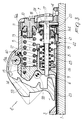
- the safety binding particularly usable for skis 1, comprises a rear engagement means, indicated by the reference numeral 2, and a front engagement means, indicated by 50.
- the front engagement means 50 is constituted by a toe unit 51 to which it is possible to impart a rotation, at least with respect to an axis 52 which is perpendicular to the ski 1, which actuates the movement, performed axially with respect to the ski 1, of a rod 3 an end whereof affects the rear engagement means 2.
- the front engagement means 50 in fact comprises a plate or spacer 53 which is rigidly associated with the ski 1 and to which a U-shaped profiled element 54 is pivoted centrally with respect to its own base; the toe unit 51 is pivoted between the wings of said profiled element 54 about an axis which is transverse to said ski 1.
- the rod 3 extends between the toe unit 51 and the rear engagement means 2, and a lug 55 protrudes from said rod and is accommodated within a cavity 56 defined in said toe unit 51.
- the lug 55 has a tab 57 which is inclined with respect to the plane of arrangement of the ski 1 so as to form an acute angle in the direction of the tip of said ski; said tab assumes, in the region directed toward the rear engagement means 2, a triangular configuration with a rounded vertex.
- the rear engagement means 2 is constituted by a heel unit which comprises a first body 4, which is associated with the ski 1, and a second body 5, which can slide with respect to the first body 4.
- first and second bodies The sliding between the first and second bodies is allowed by virtue of the presence of a pivot 6 which is arranged axially with respect to the heel unit and is rigidly associated, at one end, with a first tab 7 which protrudes rearward with respect to the first body 4; said pivot is slidingly associated, at its other end, in an adapted seat defined on the second body 5.
- a pivot 6 which is arranged axially with respect to the heel unit and is rigidly associated, at one end, with a first tab 7 which protrudes rearward with respect to the first body 4; said pivot is slidingly associated, at its other end, in an adapted seat defined on the second body 5.
- a sleeve 8 rigidly associated with the pivot 6 allows, together with an elastic contrast element 9 interposed between said sleeve and said second body, to achieve said sliding.
- the rear engagement means 2 furthermore comprises a first screw 10 which can be accessed from the outside of the second body 5 and the stem whereof interacts with a complementarily threaded first slider 11 which is guided, in its axial movement with respect to said second body 5, by a first guide 12 which is defined thereon.
- Said first slider 11 compresses a first elastically deformable element, which is constituted by a first spring 13 which interacts with an adapted cam 14 which is slidingly guided within the second body 5 by a dowel 15 which is arranged transversely to said second body within a guiding slot 15a defined longitudinally on said second body 5.
- the cam 14 interacts, in a known manner, with a roller 58 which is transversely coupled to, or associated with, the jaw 59 which is pivoted to the second body 5 by means of the pivot 60.
- the head of the first screw 10 has a first toothed ring 16a which transmits a rotary motion to a second toothed ring 16b defined on the head of a second screw 17.
- Said second screw has a hollow stem which is slidingly associated with the pivot 6 and is externally threaded; a complementarily threaded second slider 18 is associated with said stem and is guided, in its axial movement with respect to the pivot 6, by a second guide 19 which is defined on a wing of an L-shaped support 20.
- Said support 20 has, at the wing on which the second guide 19 is defined, a raised portion 21 which protrudes downward, toward the underlying ski 1, within an adapted recess 22 defined on a spacer plate 23 which is provided with a sliding seat for the rod 3.
- Said recess allows the movement of the raised portion 21 toward the toe unit associated with the ski.
- the raised portion 21 is furthermore keyed at the rod 3, so as to be rigidly associated with the movements thereof.
- the wing 24 of the support 20 which is perpendicular to the ski 1 is interposed between the tab 7, which protrudes from the first body 4, and the head of the second screw 17.
- the use of the safety binding is as follows: initially, in order to adjust the release load, a rotation is imparted, by means of adapted tools, to the first screw 10, causing the translatory motion of the first slider 11.
- Said slider compresses the first spring 13 and simultaneously, by virtue of the coupling between the first ring 16a and the second ring 16b, a rotation is imparted to the second screw 17 and causes, in turn, the movement of the second slider 18 axially with respect to the pivot 6; said second slider compresses the second spring 25.
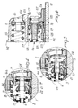
- This situation entails the simultaneous traction, by means of the wing 24 of the support 20, of the first screw 17, which can slide axially with respect to the pivot 6 rigidly with the second slider 18, as illustrated in figure 3.
- the presence of the second spring 25 contrasts said traction, thus allowing to control and adjust the release of the toe unit.
- ski binding according to the invention is susceptible to numerous modifications and variations, all of which are within the scope of the same inventive concept.
- Figure 6 illustrates a second embodiment for a safety binding, wherein specifically the rear engagement means 102 is again constituted by a heel unit which comprises a first body 104, which is associated with the ski 101, and a second body 105, which can slide with respect to the first body 104.
- the rear engagement means 102 is again constituted by a heel unit which comprises a first body 104, which is associated with the ski 101, and a second body 105, which can slide with respect to the first body 104.
- a pivot 106 which is arranged axially with respect to the heel element and has, at one end, a head 127 which is freely rotationally associated with a first tab 107 which protrudes rearward with respect to the first body 104; at its other end, said pivot is slidingly associated in an adapted seat defined on the second body 105.
- the rear engagement means 102 furthermore comprises a first screw 110, which can be accessed from the outside of the second body 105, the stem whereof interacts with a complementarily threaded first slider 111 which is suitable for compressing a first elastically deformable element, constituted by a first spring 113, which interacts with an adapted cam which is retained in position within the second body 105 by an appropriate dowel which is arranged within an appropriate guiding slot defined on said second body 105.
- the pivot 106 has a first portion 128 which is adjacent to the head 127 and is solid or hollow and has a polygonal cross-section.
- a complementarily shaped second screw 117 is associated at, and coaxially to, said first portion 128 of the pivot 106; said screw 117 is externally threaded, and a complementarily threaded second slider 118 is in turn associated therewith.
- the binding furthermore comprises an L-shaped support 120 which has a wing adjacent to the ski 101 and a wing 124 which is interposed between the tab 107, which protrudes from the first body 104, and the second screw 117.
- a raised portion 121 protrudes toward the ski 101 at the wing adjacent to said ski and is slidingly arranged within an adapted seat 122 which is defined on a spacer 123 provided with a sliding seat for the rod 103.
- Said seat 122 allows the movement of the raised portion 121 toward the toe unit associated with the ski.
- the raised portion 121 is furthermore keyed at the rod 103 so as to be rigid with the movements thereof.
- the support 120 furthermore interacts with the second screw 117 in contrast with a second elastically deformable element, constituted by a second spring 125, which is coaxial to the pivot 106.
- the adjustment of the degree of release of the front and rear engagement means can occur separately by acting on the first screw 110 and on the head 127.
Landscapes
- Footwear And Its Accessory, Manufacturing Method And Apparatuses (AREA)
Applications Claiming Priority (2)
| Application Number | Priority Date | Filing Date | Title |
|---|---|---|---|
| IT5939190U IT223065Z2 (it) | 1990-10-09 | 1990-10-09 | Struttura di attacco di sicurezza particolarmente per sci |
| IT5939190U | 1990-10-09 |
Publications (1)
| Publication Number | Publication Date |
|---|---|
| EP0480328A1 true EP0480328A1 (en) | 1992-04-15 |
Family
ID=11289356
Family Applications (1)
| Application Number | Title | Priority Date | Filing Date |
|---|---|---|---|
| EP91116957A Withdrawn EP0480328A1 (en) | 1990-10-09 | 1991-10-04 | Ski binding |
Country Status (3)
| Country | Link |
|---|---|
| EP (1) | EP0480328A1 (it) |
| JP (1) | JPH04322673A (it) |
| IT (1) | IT223065Z2 (it) |
Cited By (2)
| Publication number | Priority date | Publication date | Assignee | Title |
|---|---|---|---|---|
| EP0829281A1 (de) * | 1996-09-11 | 1998-03-18 | Marker Deutschland GmbH | Schuhhalteraggregat einer auslösbaren Skibindung |
| EP2594321A1 (de) * | 2011-11-18 | 2013-05-22 | MARKER Deutschland GmbH | Bindung für ein Gleitbrett mit Stützglied |
Citations (6)
| Publication number | Priority date | Publication date | Assignee | Title |
|---|---|---|---|---|
| DE2635686A1 (de) * | 1976-08-07 | 1978-02-09 | Bernhard Kirsch | Skibindung |
| FR2501514A1 (fr) * | 1981-03-13 | 1982-09-17 | Ess Skibindungen | Fixation de securite pour skis |
| AT371349B (de) * | 1981-06-12 | 1983-06-27 | Tyrolia Freizeitgeraete | Skibindung |
| FR2654636A1 (en) * | 1989-11-22 | 1991-05-24 | Salomon Sa | Multipurpose device for mounting a boot on a ski |
| EP0441251A1 (en) * | 1990-02-06 | 1991-08-14 | NORDICA S.p.A. | Ski fastening |
| EP0424846B1 (en) * | 1989-10-27 | 1994-03-02 | NORDICA S.p.A | Ski fastening |
-
1990
- 1990-10-09 IT IT5939190U patent/IT223065Z2/it active IP Right Grant
-
1991
- 1991-10-04 EP EP91116957A patent/EP0480328A1/en not_active Withdrawn
- 1991-10-09 JP JP29090491A patent/JPH04322673A/ja not_active Withdrawn
Patent Citations (6)
| Publication number | Priority date | Publication date | Assignee | Title |
|---|---|---|---|---|
| DE2635686A1 (de) * | 1976-08-07 | 1978-02-09 | Bernhard Kirsch | Skibindung |
| FR2501514A1 (fr) * | 1981-03-13 | 1982-09-17 | Ess Skibindungen | Fixation de securite pour skis |
| AT371349B (de) * | 1981-06-12 | 1983-06-27 | Tyrolia Freizeitgeraete | Skibindung |
| EP0424846B1 (en) * | 1989-10-27 | 1994-03-02 | NORDICA S.p.A | Ski fastening |
| FR2654636A1 (en) * | 1989-11-22 | 1991-05-24 | Salomon Sa | Multipurpose device for mounting a boot on a ski |
| EP0441251A1 (en) * | 1990-02-06 | 1991-08-14 | NORDICA S.p.A. | Ski fastening |
Cited By (3)
| Publication number | Priority date | Publication date | Assignee | Title |
|---|---|---|---|---|
| EP0829281A1 (de) * | 1996-09-11 | 1998-03-18 | Marker Deutschland GmbH | Schuhhalteraggregat einer auslösbaren Skibindung |
| US5997026A (en) * | 1996-09-11 | 1999-12-07 | Marker Deutschland Gmbh | Boot-retaining unit of a disengageable ski binding |
| EP2594321A1 (de) * | 2011-11-18 | 2013-05-22 | MARKER Deutschland GmbH | Bindung für ein Gleitbrett mit Stützglied |
Also Published As
| Publication number | Publication date |
|---|---|
| IT9059391V0 (it) | 1990-10-09 |
| IT223065Z2 (it) | 1995-06-09 |
| IT9059391U1 (it) | 1992-04-09 |
| JPH04322673A (ja) | 1992-11-12 |
Similar Documents
| Publication | Publication Date | Title |
|---|---|---|
| US6089579A (en) | Braking device particularly for skates | |
| US5374070A (en) | Braking device particularly for skates | |
| US4088342A (en) | Release binding for skis | |
| US6964428B2 (en) | Device for binding a boot to a sports article | |
| EP0183182B1 (en) | Foot securing device, particularly for ski boots | |
| US5150914A (en) | Fastening particularly for skis | |
| US5722681A (en) | Alpine ski binding apparatus | |
| JPS6121641B2 (it) | ||
| JPH01198501A (ja) | 胴部のヒンジ連結軸の傾斜調節装置を含む靴 | |
| US4194758A (en) | Brake mechanism which can be mounted on a ski | |
| US20030155744A1 (en) | Adjustment device, particularly for ski bindings | |
| US4869522A (en) | Coupled safety bindings adapted for use with monoski | |
| US4449730A (en) | Front jaw for a safety ski binding | |
| US4583757A (en) | Safety binding for ski | |
| US5282642A (en) | Apparatus for biasing | |
| EP0424846B1 (en) | Ski fastening | |
| JPH04322673A (ja) | スキービンディング | |
| EP0281051A2 (en) | Device for adjusting the flexibility in a ski boot | |
| GB2172807A (en) | Ski boot securing arrangement | |
| US3100119A (en) | Tightening device for ski bindings | |
| US11491388B2 (en) | Binding toe-piece for gliding board | |
| EP0448009B1 (en) | Safety ski binding | |
| EP0058458A1 (en) | Cross-country ski rear fastening | |
| US5388851A (en) | Alpine ski safety binding | |
| US4592569A (en) | Release ski binding |
Legal Events
| Date | Code | Title | Description |
|---|---|---|---|
| PUAI | Public reference made under article 153(3) epc to a published international application that has entered the european phase |
Free format text: ORIGINAL CODE: 0009012 |
|
| AK | Designated contracting states |
Kind code of ref document: A1 Designated state(s): AT CH DE FR IT LI |
|
| 17P | Request for examination filed |
Effective date: 19920923 |
|
| STAA | Information on the status of an ep patent application or granted ep patent |
Free format text: STATUS: THE APPLICATION HAS BEEN WITHDRAWN |
|
| 17Q | First examination report despatched |
Effective date: 19931111 |
|
| 18W | Application withdrawn |
Withdrawal date: 19931220 |