EP0480337A2 - Gasdichte Kontakthalterung eines elektrischen Verbinders und Herstellungsverfahren - Google Patents
Gasdichte Kontakthalterung eines elektrischen Verbinders und Herstellungsverfahren Download PDFInfo
- Publication number
- EP0480337A2 EP0480337A2 EP91116977A EP91116977A EP0480337A2 EP 0480337 A2 EP0480337 A2 EP 0480337A2 EP 91116977 A EP91116977 A EP 91116977A EP 91116977 A EP91116977 A EP 91116977A EP 0480337 A2 EP0480337 A2 EP 0480337A2
- Authority
- EP
- European Patent Office
- Prior art keywords
- insert
- shell
- ring
- receptacle
- annular
- Prior art date
- Legal status (The legal status is an assumption and is not a legal conclusion. Google has not performed a legal analysis and makes no representation as to the accuracy of the status listed.)
- Granted
Links
- 230000014759 maintenance of location Effects 0.000 title claims abstract description 22
- 238000004519 manufacturing process Methods 0.000 title abstract description 4
- 229910052751 metal Inorganic materials 0.000 claims abstract description 23
- 239000002184 metal Substances 0.000 claims abstract description 23
- 238000000034 method Methods 0.000 claims description 7
- 229910052782 aluminium Inorganic materials 0.000 claims description 4
- XAGFODPZIPBFFR-UHFFFAOYSA-N aluminium Chemical compound [Al] XAGFODPZIPBFFR-UHFFFAOYSA-N 0.000 claims description 4
- 230000003116 impacting effect Effects 0.000 claims 1
- 238000007789 sealing Methods 0.000 abstract description 6
- 230000008878 coupling Effects 0.000 description 13
- 238000010168 coupling process Methods 0.000 description 13
- 238000005859 coupling reaction Methods 0.000 description 13
- 238000003825 pressing Methods 0.000 description 6
- 230000006866 deterioration Effects 0.000 description 4
- 230000013011 mating Effects 0.000 description 4
- 239000004593 Epoxy Substances 0.000 description 3
- 238000003780 insertion Methods 0.000 description 3
- 230000037431 insertion Effects 0.000 description 3
- 239000000463 material Substances 0.000 description 3
- 239000004033 plastic Substances 0.000 description 3
- 238000010276 construction Methods 0.000 description 2
- 239000011159 matrix material Substances 0.000 description 2
- 238000012986 modification Methods 0.000 description 2
- 230000004048 modification Effects 0.000 description 2
- 229910000906 Bronze Inorganic materials 0.000 description 1
- RYGMFSIKBFXOCR-UHFFFAOYSA-N Copper Chemical compound [Cu] RYGMFSIKBFXOCR-UHFFFAOYSA-N 0.000 description 1
- 239000010974 bronze Substances 0.000 description 1
- 230000015556 catabolic process Effects 0.000 description 1
- 230000006835 compression Effects 0.000 description 1
- 238000007906 compression Methods 0.000 description 1
- 239000004020 conductor Substances 0.000 description 1
- 229910052802 copper Inorganic materials 0.000 description 1
- 239000010949 copper Substances 0.000 description 1
- KUNSUQLRTQLHQQ-UHFFFAOYSA-N copper tin Chemical compound [Cu].[Sn] KUNSUQLRTQLHQQ-UHFFFAOYSA-N 0.000 description 1
- 238000006731 degradation reaction Methods 0.000 description 1
- 230000001066 destructive effect Effects 0.000 description 1
- 239000003989 dielectric material Substances 0.000 description 1
- 239000007787 solid Substances 0.000 description 1
- 239000012815 thermoplastic material Substances 0.000 description 1
Images


Classifications
-
- H—ELECTRICITY
- H01—ELECTRIC ELEMENTS
- H01R—ELECTRICALLY-CONDUCTIVE CONNECTIONS; STRUCTURAL ASSOCIATIONS OF A PLURALITY OF MUTUALLY-INSULATED ELECTRICAL CONNECTING ELEMENTS; COUPLING DEVICES; CURRENT COLLECTORS
- H01R13/00—Details of coupling devices of the kinds covered by groups H01R12/70 or H01R24/00 - H01R33/00
- H01R13/40—Securing contact members in or to a base or case; Insulating of contact members
- H01R13/42—Securing in a demountable manner
- H01R13/424—Securing in base or case composed of a plurality of insulating parts having at least one resilient insulating part
-
- Y—GENERAL TAGGING OF NEW TECHNOLOGICAL DEVELOPMENTS; GENERAL TAGGING OF CROSS-SECTIONAL TECHNOLOGIES SPANNING OVER SEVERAL SECTIONS OF THE IPC; TECHNICAL SUBJECTS COVERED BY FORMER USPC CROSS-REFERENCE ART COLLECTIONS [XRACs] AND DIGESTS
- Y10—TECHNICAL SUBJECTS COVERED BY FORMER USPC
- Y10S—TECHNICAL SUBJECTS COVERED BY FORMER USPC CROSS-REFERENCE ART COLLECTIONS [XRACs] AND DIGESTS
- Y10S439/00—Electrical connectors
- Y10S439/901—Connector hood or shell
- Y10S439/903—Special latch for insert
-
- Y—GENERAL TAGGING OF NEW TECHNOLOGICAL DEVELOPMENTS; GENERAL TAGGING OF CROSS-SECTIONAL TECHNOLOGIES SPANNING OVER SEVERAL SECTIONS OF THE IPC; TECHNICAL SUBJECTS COVERED BY FORMER USPC CROSS-REFERENCE ART COLLECTIONS [XRACs] AND DIGESTS
- Y10—TECHNICAL SUBJECTS COVERED BY FORMER USPC
- Y10T—TECHNICAL SUBJECTS COVERED BY FORMER US CLASSIFICATION
- Y10T29/00—Metal working
- Y10T29/49—Method of mechanical manufacture
- Y10T29/49002—Electrical device making
- Y10T29/49117—Conductor or circuit manufacturing
- Y10T29/49204—Contact or terminal manufacturing
- Y10T29/49208—Contact or terminal manufacturing by assembling plural parts
Definitions
- the present invention relates to an insert retention, gas tight seal for an electrical connector and more particularly to a solid metal annular ring gas tight seal which becomes an integral part of the connector housing for both the receptacle and the plug.
- Expanding ring retainers for use in electrical connectors which provide limited movement and limited vibration deterioration of the connector insert are known.
- this insert member is a thin laminate which can be mechanically deformed until it substantially fills the space between the shell and the insert.
- the laminate member is made of a matrix of screen-like material, for example a wire screen, impregnated with an epoxy or other thermal setting material.
- Specific embodiments of the Bouvier device comprise a matrix material having a bronze screen.
- U.S. Patent No. 4,019,799, issued April 26, 1977 also to A.J. Bouvier, entitled “Electrical Connector”, discloses wrapping a deformable laminate around the members within an electrical connector housing and inserting the assembled members with the laminate into a shell thereby affixing the connector inserts immovable in this application.
- the laminate is a screen-like material impregnated with an epoxy.
- the Bouvier device describes a laminate deformed wherein it substantially fills the space including an annular groove within the insert of the housing. The laminate is deformed prior to the insertion of terminals using a pressure tool.
- the Gallusser, et al. patent discloses an annular groove on the inner wall and the dielectric insert having an outer periphery disposed within the connector shell so that an annular passageway is provided between the shell and the insert thereby providing a retention arrangement for retaining the insert in the shell.
- this insert retention member in the Gallusser, et al. patent incorporates an insert tool to insert and maintain the insert between the connector shell and the dielectric insert.
- the Gallusser, et al. device incorporates the use of a dielectric material such as a plastic because of the conductive path which occurs between the insert assembly and the shell when a copper mesh epoxy laminate or metal ring staking is used.
- the annular passageway formed between the connector insert and shell allows the longitudinal columns to collapse accordion style thereby radially wedging and locking in the columns in the passage and retaining the insert within the shell.
- an electrical connector having a metal shell includes an annular groove within the interior wall of the shell, wherein the dielectric insert has an outer periphery disposed within the shell so that there is an annular passageway between the shell and the insert.
- the Punako, et al. retention arrangement includes a thermoplastic material retention member longitudinally slotted along its front face providing a plurality of axially weakened columns that terminate in a leading edge such that each column can curl back 180° upon themselves to lock the forward end portion of each respective column.
- Each axially weakened column is forward of the respective column medium portion such that each column is weakened to collapsibly fold and stack in accordion-like fashion forming radial folds.
- These columns are then curled and folded after the leading edges have engaged in an axial wall of the annular groove at the end of the passageway, and the curled folded column portions interface and wedge in the passageway around the annular passageway thereby retaining the insert within the shell.
- This invention provides an insert retention, gas tight seal for an electrical connector having a housing including: a receptacle, a plug and a coupling nut, wherein the receptacle and plug each have an insulating insert which resides within the electrical connector housing or shell.
- Annular grooves are inscribed upon the interior surface of the electrical connector housing.
- Soft annealed metal cylindrical rings are inserted within the electrical connector housing for the receptacle and plug around the inserts, specifically within the annular grooves.
- a cylindrical tool operable to, under high pressure, collapse and expand the soft annular metal cylindrical rings within the annular groove thereby providing a gas tight seal.
- the present invention solves the problem of the vibrational deterioration of the insulating insert within an electrical connector as used in the construction industry for connectors subjected to high vibration.
- the invention provides an electrical connector insert retention system that can be provided in a high vibrational environmentally destructive arena guaranteeing the continued mating of the receptacle and plug without receptacle and plug insert degradation.
- a method of fabricating an insert retention gas tight seal for an electrical connector is also disclosed.
- an insert retention gas tight seal for an electrical connector comprises a standard electrical connector having a receptacle, plug and coupling nut which has annular grooves inscribed within the interior walls of the receptacle and plug shells.
- the inserts for the receptacle and plug are inserted by hand into the respective shells, and an annular aluminum or other soft metal annular ring is inserted surrounding the inserts between the interior surfaces of the receptacle shell and plug shell and the exterior surfaces of the inserts.
- a beveled cylindrical tool is pressed against the soft metal annular rings under high pressure collapsing and expanding the soft metal into the inscribed grooves of the receptacle and plug shell interior surfaces.
- the combination of the inscribed grooves, the soft metal impressed within the grooves, and the receptacle and plug shell interior surfaces create a gas tight seal surrounding the inserts and a stable support for the inserts when they are subjected to high vibration.
- Figure 1 is a schematic representation exploded cross sectional view of a connector 5 having a receptacle and a plug, each incorporating an insert retention, gas tight seal with the receptacle and plug connectors to be secured together with a coupling nut 14.
- the shell 10 of the receptacle has a top 16 and bottom 18 as viewed in Figure 1. Protruding from the top 16 of the receptacle shell 10 is the first receptacle insert 26.
- This insert 26 has a plurality of orifices 27 adapted to receive wires (not shown) connected to the pins 38 as is well known in the art.
- First receptacle insert 26 rests upon a second receptacle insert 28.
- the interior surface 24 of the receptacle shell is inscribed by an annular groove 22 at a point upon the interior surface 24 where the first insert 26 and second insert 28 are matingly joined.
- An annular insert retaining ring 44 is mounted within the inscribed groove 22.
- the annular insert retaining ring 44 of this example is soft annealed aluminum.
- a third receptacle insert 30 rests below and is joined with the second receptacle insert 28. Electrically conductive metal pins 38 protrude from the third receptacle insert 30. These metal pins 38 are operable to enter the orifices 101 of the plug and mate with female contacts therein.
- Wires extend through the first receptacle insert 26 through orifices 27 and through the first receptacle insert cavities 32, second receptacle insert cavities 34 and third receptacle insert cavities 36 where their ends interconnect with the metal pins 38.
- a wall mounting flange 46 having two mounting orifices 130,130' is operable to facilitate the wall mounting of the receptacle to a fixed planar surface.
- the threads so formed on the interior surface 78 of the coupling nut 14 engage the threads 42 of the receptacle shell 10 to mechanically and electrically secure together the plug and receptacle.
- bottom 18 defines an annular sealing means 48 of the receptacle shell which matingly engages the annular side flange 60 of the plug shell when the receptacle and plug connectors are mated.
- O-ring 95 serves as a primary seal between the receptacle shell 10 and plug shell 12.
- the top 52 of the plug shell 12 matingly interfits within the bottom 18 of the receptacle shell 10 such that the exterior surface of the plug 56 slidably interfits within the interior surface 24 of the receptacle shell 10 with key 43 extending along a corresponding keyway of the plug shell 12.
- the metal pins 38 of the receptacle connector enter the holes 101 within the plug first insert means 68 and pass into the plug first insert cavities 72 to engage female electrical contacts (see Figure 6), residing therein. Electrical wires (not shown) fastened to the female electrical contacts pass through the plug second insert 70 and through plug second insert cavities 74.
- the plug 12 has its interior surface 58 inscribed with an annular groove 62.
- An annular retaining ring 64 for the plug provides insert 68 stability, and a gas tight seal for the plug.
- the coupling nut 14 lockingly engages the plug shell 12 and receptacle shell 10 when its exterior surface 76 is turned with threads 80 of ring 14 engaging with threads 42 of receptacle shell 10.
- Figure 2 is a schematic representation exploded orthogonal view of the tool pressing in the receptacle annular retaining ring around the first insert of the receptacle. This process would be identical for the pressing of the annular ring in the plug shell 12 (not shown here).
- the tool 84 having a flat top 86 which can be subjected to pressure, a shank 88 ending with a beveled edge 90 slidingly interfits between the outer surface of first insert 26 and the interior surface 24 of first receptacle shell 10.
- Annular ring 44 rests within an inscribed groove 22 within the interior surface 24 of the receptacle shell 10.
- This inscribed groove 22 is positioned upon the interior surface 24 of the receptacle shell 10 between the first insert 26 and the second insert 28.
- the tool 84 is placed upon the annular ring 44 it is subjected to a force of between 100 and 150 psi (approx. 600 to 1100 KN ⁇ m ⁇ 2). This force compresses the annular ring within the inscribed groove 22.
- This gas tight seal formed by the annular ring 44 is an integral part of the interior surface 24 of the receptacle shell 10. The gas tight seal also provides increased structural support to the inserts 26,28.
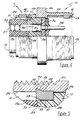
- Figure 3 is a partial cross sectional view schematic representation of the process of the tool 84 pressing in the annular insert retention gas tight seal.
- the receptacle shell 10 has an annular groove 22 inscribed within the interior surface 24 of the receptacle shell 10.
- the annular ring 44 having an annular ring exterior surface 49 and an annular ring interior surface 47, resides within the annular groove 22.
- the interior surface 47 of the annular ring 44 is forced against the first 26 and second 28 inserts of the receptacle connector, while the exterior surface 49 of the ring 44 presses against the interior surface 24 of the receptacle shell 10 within the groove 22.
- F in the range of 100 to 150 psi (approx.
- Figure 4 is a schematic representation partial cross sectional view of the receptacle connector while Figure 5 is an enlarged view of the annular ring 46 forming the seal.
- the receptacle shell 10 has an annular groove 22 inscribed within the interior surface 24 thereof.
- An annular ring 44 is positioned between the interior surface 24 of the receptacle shell 10 and the exterior surface of insert 28.
- the top 16 of the first insert 26 has a hole 27 operable to receive an electrical wire (not shown here) having a contact pin 38 electrically connected to its leading end and which would have been inserted through the first insert cavity 32 and second insert cavity 34. Wires terminated with a soldered connection are terminated before the terminals are assembled to the inserts.
- the pin 38 is held in place within the third insert cavity 36 by a clip retaining means 41.
- the annular sealing means 48 at the bottom 18 of the receptacle engages the annular sealing means 55 of the plug ( Figure 7) forming a seal.
- Conductor wires are clamped after insertion by reduced diameter portions of cavity portions 32 for mechanical vibration and seal support benefits.
- the second threaded 42 means of the receptacle shell 10 and key 43 with a corresponding keyway of plug shell 12 serve to align the receptacle shell 10 with the plug shell 12.
- the annular ring 44 provides a seal within the opening 51 between the interior surface 24 of the receptacle shell 10 and the inserts 26,28.
- Figure 5 is a partial cross sectional view schematic representation of the pressed-in receptacle annular ring of Figure 4.
- the receptacle shell 10 has inscribed surface groove 22 wherein annular ring 44 is pressed.
- the open area 51 within the space formed by the interior surface 24 of the receptacle shell 10 and the insert 26 is blocked by the top 53 of the ring 44.
- the pressing of the ring 44 results in the compression of ring 44 forwardly against an enlarged diameter portion of insert 28, and of the interior surface 47 of the ring against exterior surface of the insert, and the exterior surface 49 against the bottom surface of annular groove 22.
- the compressed ring 44 provides support to the inserts where they mate at bonded interface 39 wherein the bottom 33 of the first insert 26 is joined to the top 35 of the second insert 28.
- the annular ring 44 is shown in relation to the exterior surface 50 of the receptacle shell 10 and first threaded means 40.
- Figure 6 is a schematic representation partial cross sectional view of the connector plug and coupling nut having insert view 7.
- the plug shell 12 has a top 52 and bottom 54.
- the coupling nut 14 is shown matingly engaged to the plug shell 12 by coupling nut retaining ring 80 and the receptacle second threaded means 42 ( Figure 4).
- Electrical wires (not shown) are operable to enter the second plug insert cavity 74 and be electrically connected to the female electrical contact 102 having either crimped or soldered terminations.
- a receptacle connector having metal pins 38 when matingly engaged with the plug connector transmit electrical signals from the pins 38 which enter the plug through holes 101 to the female contacts 102 within the first insert cavity 72.
- the gas tight seal within the plug connector is accomplished by first inscribing an annular groove 62 within the interior surface 58 of the plug shell 12.
- An annular plug ring 64 of a soft metal is then slidably interfit around the second insert means 70 and the interior surface 58 of the plug shell.
- a metal tool similar to tool 84 of Figure 2, impresses and compresses the annular plug ring 64 within the inscribed groove 62 providing mechanical support for the bonded-together first and second inserts 68,70.
- An O-ring 95 serves as a secondary seal when it is placed between the coupling nut 14 and plug within the annular side flange 60. It is an industry standard in some connectors to bond the O-ring 95 within the front of the shell of the plug connector.
- FIG 7 is a schematic representation partial cross sectional view of the secondary seal between the plug connector and the coupling nut of Figure 6.
- the plug shell 12 with exterior 56 has an annular side flange 60 of the plug shell 12.
- the O-ring 95 fits within the flange 60 between the annular sealing edge 48 of the receptacle shell 10, sealing between the interior of the front of receptacle shell 10 and the exterior of the front of plug shell 12.
- the interior 58 of the plug shell 12 rests against the first 68 and second 70 insert means due to a force fitting relationship.
- This O-ring 95 serves as a secondary seal for the open area 110 between the mating surfaces of the receptacle shell 10 and plug shell 12.
- a method of providing this gas tight seal for the retainage of the insert includes: the grooving of the interior surface of the receptacle and plug shells, the insertion of a separate annular ring of aluminum or other annealed soft metal around the insert, placing around the inserts within the receptacle and plug rings a tool, compressing and collapsing the soft annealed ring into a position surrounding the insert providing a gas tight free seal to support the insert.
- the completed seal appears as one complete unit of the ring and housing.
Landscapes
- Connector Housings Or Holding Contact Members (AREA)
- Manufacturing Of Electrical Connectors (AREA)
Applications Claiming Priority (2)
| Application Number | Priority Date | Filing Date | Title |
|---|---|---|---|
| US59507490A | 1990-10-09 | 1990-10-09 | |
| US595074 | 1990-10-09 |
Publications (3)
| Publication Number | Publication Date |
|---|---|
| EP0480337A2 true EP0480337A2 (de) | 1992-04-15 |
| EP0480337A3 EP0480337A3 (en) | 1992-08-19 |
| EP0480337B1 EP0480337B1 (de) | 1995-08-09 |
Family
ID=24381620
Family Applications (1)
| Application Number | Title | Priority Date | Filing Date |
|---|---|---|---|
| EP91116977A Expired - Lifetime EP0480337B1 (de) | 1990-10-09 | 1991-10-04 | Gasdichte Kontakthalterung eines elektrischen Verbinders und Herstellungsverfahren |
Country Status (4)
| Country | Link |
|---|---|
| US (2) | US5295866A (de) |
| EP (1) | EP0480337B1 (de) |
| JP (1) | JPH04262377A (de) |
| DE (1) | DE69111962T2 (de) |
Cited By (2)
| Publication number | Priority date | Publication date | Assignee | Title |
|---|---|---|---|---|
| EP2498345A1 (de) * | 2007-04-30 | 2012-09-12 | Tronic Limited | Steckverbinder |
| US8585423B2 (en) | 2007-04-30 | 2013-11-19 | Siemens Aktiengesellschaft | Submersible electrical connector |
Families Citing this family (20)
| Publication number | Priority date | Publication date | Assignee | Title |
|---|---|---|---|---|
| US5399095A (en) * | 1991-03-26 | 1995-03-21 | Square D Company | Variable phase positioning device |
| DE4418259C1 (de) * | 1994-05-25 | 1995-08-24 | Hirschmann Richard Gmbh Co | Mehrpoliger Kabelsteckverbinder |
| US5980317A (en) * | 1998-03-13 | 1999-11-09 | Geo Space Corporation | Repairable electrical geophysical connector |
| US6319073B1 (en) * | 1999-12-16 | 2001-11-20 | Amphenol Corporation | Hybrid submarine streamer connector |
| JP2001257028A (ja) * | 2000-03-10 | 2001-09-21 | Yazaki Corp | コネクタ結合構造 |
| EP1180823B1 (de) * | 2000-08-09 | 2004-06-02 | Phoenix Contact GmbH & Co. KG | Kabelanschluss- oder -verbindungseinrichtung |
| FR2839815B1 (fr) * | 2002-05-15 | 2004-06-25 | Positronic Ind | Procede de scellage de contacts de connecteur de traversee de cloison de type coaxiaux, contact coaxial adapte et connecteur ainsi obtenu |
| US7144268B2 (en) * | 2003-08-19 | 2006-12-05 | Spacelabs Medical, Inc. | Latching medical patient parameter safety connector and method |
| US7165980B2 (en) * | 2004-05-13 | 2007-01-23 | Thomas & Betts International, Inc. | Conduit bushing with revolving lug |
| EP1628370B1 (de) * | 2004-08-20 | 2012-11-07 | Continental Automotive GmbH | Elektrische Verbindungsvorrichtung |
| FR2879837B1 (fr) * | 2004-12-16 | 2015-07-24 | Radiall Sa | Adaptateur pour connecteur multicontacts et un tel connecteur. |
| US7517258B1 (en) * | 2006-01-31 | 2009-04-14 | H-Tech, Llc | Hermetically sealed coaxial type feed-through RF Connector |
| US20080139030A1 (en) * | 2006-12-08 | 2008-06-12 | Scully Signal Company | Electrical socket assembly for tanker truck overfill prevention system |
| JP5242311B2 (ja) * | 2008-09-22 | 2013-07-24 | 三菱電線工業株式会社 | シール挿入方法及びその装置 |
| US8035030B2 (en) * | 2009-04-13 | 2011-10-11 | Robert Bosch Gmbh | Hermetically sealed electrical connection assembly |
| EP2330707A1 (de) * | 2009-12-03 | 2011-06-08 | Tyco Electronics Raychem BVBA | Gelabdichtungsvorrichtung |
| DK2330706T3 (da) * | 2009-12-03 | 2017-08-21 | CommScope Connectivity Belgium BVBA | Geletætningsenhed |
| DK3176890T3 (da) | 2012-07-02 | 2020-05-18 | CommScope Connectivity Belgium BVBA | Kabeltætningsenhed med flere tætningsmoduler |
| US9048584B2 (en) * | 2013-01-31 | 2015-06-02 | Tyco Electronics Corporation | Electrical connector system having an insulator holding terminals |
| JP6941270B2 (ja) * | 2017-01-30 | 2021-09-29 | 住友電気工業株式会社 | 流体封止装置、及び電力ケーブル線路 |
Family Cites Families (30)
| Publication number | Priority date | Publication date | Assignee | Title |
|---|---|---|---|---|
| US913595A (en) * | 1908-10-22 | 1909-02-23 | Fred H Weinhauer | Spark-plug. |
| US2466057A (en) * | 1947-02-18 | 1949-04-05 | Somma Raymond | Combined tube connector and tube flarer |
| US2687906A (en) * | 1949-01-26 | 1954-08-31 | Wagner Electric Corp | Swaged type metallic pipe fitting |
| US2989784A (en) * | 1957-10-04 | 1961-06-27 | Bell Telephone Labor Inc | Method of forming a plug of high melting point plastic bonded to a low melting point plastic |
| FR1206968A (fr) * | 1958-05-24 | 1960-02-12 | Raccord de conducteurs électriques | |
| DE1273032B (de) * | 1963-11-30 | 1968-07-18 | Rohde & Schwarz | Steckerkupplung fuer Koaxialleitungen |
| US3373243A (en) * | 1966-06-06 | 1968-03-12 | Bendix Corp | Electrical multiconductor cable connecting assembly |
| GB1183819A (en) * | 1966-09-23 | 1970-03-11 | British Insulated Callenders | Improvements in or relating to Electric Cable Terminations. |
| US3529856A (en) * | 1969-01-08 | 1970-09-22 | Dumont Aviat Associates | Coupling and method of forming same |
| US3646502A (en) * | 1970-08-24 | 1972-02-29 | Bunker Ramo | Connector element and method for element assembly |
| US3644874A (en) * | 1970-10-07 | 1972-02-22 | Bunker Ramo | Connector element and method for element assembly |
| US3810073A (en) * | 1973-01-26 | 1974-05-07 | Omni Spectra Inc | Connector locking mechanism |
| DE2317700A1 (de) * | 1973-04-09 | 1974-10-24 | Norddeutsche Seekabelwerke Ag | Druckwasserdichte steckverbindung fuer elektrische kabel |
| US3836700A (en) * | 1973-12-06 | 1974-09-17 | Alco Standard Corp | Conduit coupling |
| US3888522A (en) * | 1974-04-01 | 1975-06-10 | Weatherhead Co | Flareless fitting |
| US3917373A (en) * | 1974-06-05 | 1975-11-04 | Bunker Ramo | Coupling ring assembly |
| US4019799A (en) * | 1976-02-11 | 1977-04-26 | The Bendix Corporation | Electrical connector |
| US4074927A (en) * | 1976-07-26 | 1978-02-21 | Automation Industries, Inc. | Electrical connector with insert member retaining means |
| US4059330A (en) * | 1976-08-09 | 1977-11-22 | John Schroeder | Solderless prong connector for coaxial cable |
| US4296992A (en) * | 1977-09-26 | 1981-10-27 | Bunker Ramo Corporation | Electrical connector assembly |
| US4389081A (en) * | 1980-11-14 | 1983-06-21 | The Bendix Corporation | Electrical connector coupling ring |
| US4413875A (en) * | 1981-09-23 | 1983-11-08 | Matrix Science Corporation | Connector retaining apparatus |
| US4544224A (en) * | 1982-09-07 | 1985-10-01 | International Telephone & Telegraph Corp. | Self-locking electrical connector |
| US4647086A (en) * | 1983-12-27 | 1987-03-03 | Brass-Craft Manufacturing Company | Tube coupling |
| FR2582870B1 (fr) * | 1985-06-04 | 1987-07-24 | Socapex | Connecteur electrique a element de retention deformable et procede d'assemblage d'un tel connecteur |
| US4682832A (en) * | 1985-09-27 | 1987-07-28 | Allied Corporation | Retaining an insert in an electrical connector |
| US4703987A (en) * | 1985-09-27 | 1987-11-03 | Amphenol Corporation | Apparatus and method for retaining an insert in an electrical connector |
| US4810209A (en) * | 1987-05-28 | 1989-03-07 | Amphenol Corporation | Pressurized electrical connector and method of assembly |
| US4871328A (en) * | 1988-09-14 | 1989-10-03 | Simmonds Precision Products, Inc. | Hermetically sealing connector and method of use thereof |
| US4920643A (en) * | 1988-09-26 | 1990-05-01 | Microwave Development Laboratories | Method of assembling electrical connector |
-
1991
- 1991-10-04 EP EP91116977A patent/EP0480337B1/de not_active Expired - Lifetime
- 1991-10-04 DE DE69111962T patent/DE69111962T2/de not_active Expired - Fee Related
- 1991-10-09 JP JP3289475A patent/JPH04262377A/ja active Pending
-
1992
- 1992-01-13 US US07/821,345 patent/US5295866A/en not_active Expired - Fee Related
-
1994
- 1994-03-22 US US08/216,005 patent/US5425171A/en not_active Expired - Fee Related
Cited By (2)
| Publication number | Priority date | Publication date | Assignee | Title |
|---|---|---|---|---|
| EP2498345A1 (de) * | 2007-04-30 | 2012-09-12 | Tronic Limited | Steckverbinder |
| US8585423B2 (en) | 2007-04-30 | 2013-11-19 | Siemens Aktiengesellschaft | Submersible electrical connector |
Also Published As
| Publication number | Publication date |
|---|---|
| EP0480337A3 (en) | 1992-08-19 |
| DE69111962T2 (de) | 1995-11-23 |
| US5295866A (en) | 1994-03-22 |
| JPH04262377A (ja) | 1992-09-17 |
| DE69111962D1 (de) | 1995-09-14 |
| US5425171A (en) | 1995-06-20 |
| EP0480337B1 (de) | 1995-08-09 |
Similar Documents
| Publication | Publication Date | Title |
|---|---|---|
| EP0480337B1 (de) | Gasdichte Kontakthalterung eines elektrischen Verbinders und Herstellungsverfahren | |
| US3787796A (en) | Low cost sealed connector and method of making same | |
| US5217392A (en) | Coaxial cable-to-cable splice connector | |
| EP2556565B1 (de) | Elektromagnetische abschirmungsvorrichtung | |
| EP0112618B1 (de) | Verbindungsvorrichtung mit einem wärmeschrumpfbaren metallenen Mitnehmerglied | |
| KR101248696B1 (ko) | 외부 도체와 축방향 압축 접속되는 접속기 및 제조 방법 | |
| US4280749A (en) | Socket and pin contacts for coaxial cable | |
| US4820181A (en) | Watertight connector | |
| EP0216124A2 (de) | Vorrichtung und Verfahren zum Halten eines Einschubs in einem elektrischen Verbinder | |
| US4150866A (en) | Environmentally sealed connector | |
| US3245027A (en) | Coaxial connector | |
| EP2398117B1 (de) | Koaxialkabelstecker | |
| US5695357A (en) | Cable connector kit, cable connector assembly and related method | |
| US5482480A (en) | Connector terminal | |
| JP3032783B2 (ja) | 導体圧着用ダイス型及び圧着方法 | |
| US4991289A (en) | Crimping die and crimped electrical connection therefrom | |
| US3409864A (en) | Sealed electrical connecting device | |
| US3853377A (en) | Tight fitting plug connection and method for making same | |
| US5372516A (en) | Waterproof connector | |
| EP0560668B1 (de) | Reparierbarer Steckverbinder | |
| EP0026692A1 (de) | Einstückiger elektrischer Kontakt | |
| JP2953961B2 (ja) | コネクタの製造方法 | |
| US4373262A (en) | Electrical contact with locking device | |
| JPH09270282A (ja) | 同軸コネクター | |
| US6475035B1 (en) | Multipolar plug-in connection |
Legal Events
| Date | Code | Title | Description |
|---|---|---|---|
| PUAI | Public reference made under article 153(3) epc to a published international application that has entered the european phase |
Free format text: ORIGINAL CODE: 0009012 |
|
| AK | Designated contracting states |
Kind code of ref document: A2 Designated state(s): DE FR GB SE |
|
| PUAL | Search report despatched |
Free format text: ORIGINAL CODE: 0009013 |
|
| AK | Designated contracting states |
Kind code of ref document: A3 Designated state(s): DE FR GB SE |
|
| 17P | Request for examination filed |
Effective date: 19930217 |
|
| 17Q | First examination report despatched |
Effective date: 19940926 |
|
| GRAA | (expected) grant |
Free format text: ORIGINAL CODE: 0009210 |
|
| AK | Designated contracting states |
Kind code of ref document: B1 Designated state(s): DE FR GB SE |
|
| REF | Corresponds to: |
Ref document number: 69111962 Country of ref document: DE Date of ref document: 19950914 |
|
| ET | Fr: translation filed | ||
| PLBE | No opposition filed within time limit |
Free format text: ORIGINAL CODE: 0009261 |
|
| STAA | Information on the status of an ep patent application or granted ep patent |
Free format text: STATUS: NO OPPOSITION FILED WITHIN TIME LIMIT |
|
| 26N | No opposition filed | ||
| PGFP | Annual fee paid to national office [announced via postgrant information from national office to epo] |
Ref country code: SE Payment date: 19981007 Year of fee payment: 8 |
|
| PGFP | Annual fee paid to national office [announced via postgrant information from national office to epo] |
Ref country code: DE Payment date: 19981028 Year of fee payment: 8 |
|
| PG25 | Lapsed in a contracting state [announced via postgrant information from national office to epo] |
Ref country code: SE Free format text: THE PATENT HAS BEEN ANNULLED BY A DECISION OF A NATIONAL AUTHORITY Effective date: 19991030 |
|
| EUG | Se: european patent has lapsed |
Ref document number: 91116977.9 |
|
| PG25 | Lapsed in a contracting state [announced via postgrant information from national office to epo] |
Ref country code: DE Free format text: LAPSE BECAUSE OF NON-PAYMENT OF DUE FEES Effective date: 20000801 |
|
| PGFP | Annual fee paid to national office [announced via postgrant information from national office to epo] |
Ref country code: FR Payment date: 20011005 Year of fee payment: 11 |
|
| REG | Reference to a national code |
Ref country code: GB Ref legal event code: IF02 |
|
| PGFP | Annual fee paid to national office [announced via postgrant information from national office to epo] |
Ref country code: GB Payment date: 20020913 Year of fee payment: 12 |
|
| PG25 | Lapsed in a contracting state [announced via postgrant information from national office to epo] |
Ref country code: FR Free format text: LAPSE BECAUSE OF NON-PAYMENT OF DUE FEES Effective date: 20030630 |
|
| REG | Reference to a national code |
Ref country code: FR Ref legal event code: ST |
|
| PG25 | Lapsed in a contracting state [announced via postgrant information from national office to epo] |
Ref country code: GB Free format text: LAPSE BECAUSE OF NON-PAYMENT OF DUE FEES Effective date: 20031004 |
|
| GBPC | Gb: european patent ceased through non-payment of renewal fee |
Effective date: 20031004 |