EP0480341A1 - Hybrid-Matrix Verstärkersystem mit gleichmässiger Verlustwärmeverteilung und Verfahren dazu - Google Patents
Hybrid-Matrix Verstärkersystem mit gleichmässiger Verlustwärmeverteilung und Verfahren dazu Download PDFInfo
- Publication number
- EP0480341A1 EP0480341A1 EP91117006A EP91117006A EP0480341A1 EP 0480341 A1 EP0480341 A1 EP 0480341A1 EP 91117006 A EP91117006 A EP 91117006A EP 91117006 A EP91117006 A EP 91117006A EP 0480341 A1 EP0480341 A1 EP 0480341A1
- Authority
- EP
- European Patent Office
- Prior art keywords
- input
- amplifiers
- hybrid
- output
- multiport
- Prior art date
- Legal status (The legal status is an assumption and is not a legal conclusion. Google has not performed a legal analysis and makes no representation as to the accuracy of the status listed.)
- Withdrawn
Links
- 239000011159 matrix material Substances 0.000 title claims abstract description 17
- 238000000034 method Methods 0.000 title description 3
- 230000008054 signal transmission Effects 0.000 claims 4
- 230000003321 amplification Effects 0.000 description 3
- 238000010586 diagram Methods 0.000 description 3
- 238000003199 nucleic acid amplification method Methods 0.000 description 3
- SAZUGELZHZOXHB-UHFFFAOYSA-N acecarbromal Chemical compound CCC(Br)(CC)C(=O)NC(=O)NC(C)=O SAZUGELZHZOXHB-UHFFFAOYSA-N 0.000 description 2
- 238000003491 array Methods 0.000 description 1
- 230000005540 biological transmission Effects 0.000 description 1
- 230000001427 coherent effect Effects 0.000 description 1
- 230000010363 phase shift Effects 0.000 description 1
Images

Classifications
-
- H—ELECTRICITY
- H03—ELECTRONIC CIRCUITRY
- H03F—AMPLIFIERS
- H03F3/00—Amplifiers with only discharge tubes or only semiconductor devices as amplifying elements
- H03F3/60—Amplifiers in which coupling networks have distributed constants, e.g. with waveguide resonators
- H03F3/602—Combinations of several amplifiers
-
- H—ELECTRICITY
- H03—ELECTRONIC CIRCUITRY
- H03F—AMPLIFIERS
- H03F2200/00—Indexing scheme relating to amplifiers
- H03F2200/198—A hybrid coupler being used as coupling circuit between stages of an amplifier circuit
Definitions
- This invention relates to amplifier hybrid matrices, especially such matrices used with a multiple beam antenna, and to methods for balancing, and equally distributing the thermal load from such systems.
- amplifier hybrid matrices have been physically arrayed, as in three-axis spacecraft, by dividing them, matrix-by-matrix, between the radiator panels in such devices.
- Such arrays impose design constraints on the multiple beam antennas used with such spacecraft, and often produce unbalanced thermal loads between or among the radiator panels in such craft, even where such matrices are evenly distributed between or among the radiator panels in such spacecraft.
- Such a thermally-balanced hybrid matrix amplifier system includes an input multiport hybrid coupler system including n x 2n-1 hybrid couplers, where n is an integer equal to or greater than 1, divided into n stages. Each of these stages includes 2n-1 hybrid couplers.
- the input multiport hybrid coupler system has N input terminals, where N is equal to 2n, and N output terminals. Connected to the N output terminals of the input multiport hybrid coupler system are N amplifiers. Connected to the outputs of the N amplifiers is an output multiport hybrid coupler system.
- This output system includes N input terminals connected to the outputs of the N amplifiers.
- the output multiport hybrid coupler system also includes n x 2 n-1 hybrid couplers divided into n stages where n is an integer equal to or greater than 1 with each stage including 2 n-1 hybrid couplers.
- the output multiport hybrid coupler system is identical in layout to the input multiport hybrid coupler system. However, its input and output terminals are reversed from those of the input multiport hybrid coupler system, and its input terminals are connected to the N amplifiers in an order reversed from that of the output terminals of the input multiport hybrid coupler system.
- these systems also include strategically-placed phase shifters.
- the phase shifters are used to vary the relative phases of the signals appearing at the amplifier inputs and, thus, to change the net signal characteristics seen by the amplifiers.
- the N amplifiers are divided into two groups, with each group including half of the amplifiers.
- Each of these groups dissipates substantially the same thermal energy during operation of the amplifier hybrid matrix system, regardless of the relative power of input signals.
- each of these amplifier groups is positioned adjacent to radiator panels to dissipate the thermal energy that the amplifiers emit during operation.
- radiator panels are affixed on the walls of a three-axis spacecraft that receives signals from a multiple beam antenna.
- Such panels are preferably of substantially the same size and have substantially the same capacity to dissipate thermal energy.
- the radiator panels are preferably sized closely to the average thermal requirements at full signal loading. Formerly, such panels were oversized to accommodate power dissipation swings resulting from thermal loading imbalance between amplifier groups.
- Embodiments of these systems that are adapted to present any one signal to the input multiport hybrid system at more than one input terminal include means for placing the signal at the same phase at each of these terminals.
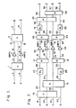
- FIG. 1 shows an amplifier hybrid matrix system of this invention including one input stage containing hybrid coupler 1, and an output hybrid coupler 2.
- Input hybrid coupler 1 includes two inputs 3 and 4 and two outputs 5 and 6. Outputs 5 and 6 form inputs to amplifiers 7 and 8 respectively.
- Output 9 from amplifier 7 and output 10 from amplifier 8 are connected as inputs 11 and 12 to coupler 2.
- the output ports 13 and 14 on output hybrid coupler 2 carry amplifications of input signals presented to input terminals 3 and 4, but in reverse order.
- the input signal on path 4 appears on output path 13; the input signal on path 3, on output path 14.
- amplifier 7 dissipates substantially the same amount of heat energy as amplifier 8.
- FIG. 2 shows an amplifier hybrid matrix system including two input stages.
- the first of these input stages includes hybrid couplers 15 and 16 in the first stage, and hybrid couplers 17 and 18 in the second stage.
- Hybrid coupler 15 has two input ports 19 and 21.
- Hybrid coupler 16 has two input ports of 20 and 22.
- Coupler 15 also has two output ports 23 and 24.
- Coupler 16 has two output ports 25 and 26.
- Output port 23 is connected to phase shifter 27; output port 26, to phase shifter 28.
- Phase shifter 27 is connected to coupler 17 via path 29.
- Phase shifter 28 is connected to coupler 18 via path 30. Signals from output port 25 of coupler 16 pass to coupler 17. Signals from output port 24 pass to coupler 18.
- Couplers 17 and 18 pass on paths 31, 32, 33 and 34 to amplifiers 35, 36, 37 and 38 respectively. Outputs from amplifiers 35-38 pass on paths 39, 40, 41 and 42 as inputs to output hybrid couplers 43 and 44. Signals on paths 47 and 50 from inputs to phase shifters 51 and 52 with outputs 53 and 54, respectively. Signals on paths 53 and 49 form inputs to coupler 45, and signals on paths 48 and 54 form inputs at coupler 46. Outputs from couplers 45 and 46 appear at output ports 55, 56, 57 and 58.
- the amplifier hybrid matrix system of FIG. 2 includes an input multiport hybrid coupler with n stages where n is an integer equal to or greater than 1, namely 2, with each stage including 2 n-1 couplers (i.e. 2 1 ) or four couplers in all, namely couplers 15, 16, 17 and 18.
- the output multiport hybrid coupler array in FIG. 2 also includes n stages, here where n is 2, that include a total of n x 2 n-1 (i.e. 2 x 2 1 ) or four couplers, namely couplers 43, 44, 45 and 46.
- the input multiport hybrid coupler system is joined to N amplifiers where N equals 2 n , i.e. 2 2 or 4. These N amplifiers are connected to N (i.e.
- amplifiers 35 and 36 are substantially equal to the total heat dissipated in amplifiers 37 and 38.
- These amplifiers can be formed into two groups, each containing the same number of amplifiers. Here, one group includes amplifiers 35 and 36; the other group, amplifiers 37 and 38. Each group then produces substantially equal average power output, and substantially the same thermal load.
- each group produces substantially equal average power output, and substantially the same thermal load, can be demonstrated mathematically.
- the symbols A, B, C and D represent arbitrary amplitude weightings of coherent input signals. If X 35 , X 36 , X 37 and X 38 are complex amplitudes of the signals at the amplifier inputs 35, 36, 37 and 38, then X 35 , X 36 , X 37 and X 38 can be expressed mathematically as follows:
- the power at each amplifier input can be expressed as follows:
- the power at amplifier input 35 is substantially the same as the power at amplifier input 38, and the power at amplifier input 36 is substantially the same as the power at amplifier input 37.
- amplifiers 35-38 are of substantially the same size and design, the output power and thermal dissipation from these two amplifier groups is also substantially the same.
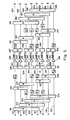
- FIG. 3 is a third embodiment of the amplifier hybrid matrix system of this invention.
- the input multiport hybrid coupler system (IH) 170 includes three input stages (i.e. n is 3).
- the first input stage includes couplers 101, 102, 103 and 104.
- the second input stage includes couplers 105, 106, 107 and 108.
- the third input stages includes couplers 109, 110, 111 and 112.
- the input system includes n (i.e. 3) stages, with each stage including 2 n-1 couplers (i.e. 2 3-1 ), or 4 couplers.
- the nth (i.e. 3rd) stage formed by couplers 109-112, includes N outputs 121, 122, 123, 124, 125, 126, 127 and 128. These N outputs form N inputs to N (i.e. 8) amplifiers 129, 130, 131, 132, 133, 134, 135 and 136.
- the N (i.e. 8) outputs of these amplifiers 129-136 are connected to N input terminals of the output multiport hybrid coupler system (OH) 172.
- This output system also has three stages.
- the output multiport hybrid coupler system 172 in its first stage, includes couplers 137, 138, 139 and 140.
- the second stage includes couplers 141, 142, 143 and 144.
- the third output stage includes couplers 145, 146, 147 and 148.
- the output multiport hybrid coupler system 172 also has N (i.e. 8) outputs appearing on paths 149, 150, 151, 152, 153, 154, 155 and 156.
Landscapes
- Engineering & Computer Science (AREA)
- Power Engineering (AREA)
- Amplifiers (AREA)
- Microwave Amplifiers (AREA)
Applications Claiming Priority (2)
| Application Number | Priority Date | Filing Date | Title |
|---|---|---|---|
| US07/594,472 US5055798A (en) | 1990-10-09 | 1990-10-09 | Hybrid matrix amplifier systems, and methods for making thermally-balanced hybrid matrix amplifier systems |
| US594472 | 1990-10-09 |
Publications (1)
| Publication Number | Publication Date |
|---|---|
| EP0480341A1 true EP0480341A1 (de) | 1992-04-15 |
Family
ID=24379025
Family Applications (1)
| Application Number | Title | Priority Date | Filing Date |
|---|---|---|---|
| EP91117006A Withdrawn EP0480341A1 (de) | 1990-10-09 | 1991-10-05 | Hybrid-Matrix Verstärkersystem mit gleichmässiger Verlustwärmeverteilung und Verfahren dazu |
Country Status (5)
| Country | Link |
|---|---|
| US (1) | US5055798A (de) |
| EP (1) | EP0480341A1 (de) |
| JP (1) | JPH04227108A (de) |
| AU (1) | AU622369B1 (de) |
| CA (1) | CA2050846C (de) |
Cited By (1)
| Publication number | Priority date | Publication date | Assignee | Title |
|---|---|---|---|---|
| RU2122279C1 (ru) * | 1996-08-28 | 1998-11-20 | Акционерное общество "Московский научно-исследовательский институт радиосвязи" | Регулятор комплексных амплитуд |
Families Citing this family (11)
| Publication number | Priority date | Publication date | Assignee | Title |
|---|---|---|---|---|
| US5378999A (en) * | 1993-08-16 | 1995-01-03 | The United States Of America As Represented By The United States Department Of Energy | Hybrid matrix amplifier |
| MX9505173A (es) * | 1995-07-19 | 1997-05-31 | Radio Frequency Systems Inc | Sistema de reparticion de energia para amplificadores de rf. |
| JPH0964758A (ja) * | 1995-08-30 | 1997-03-07 | Matsushita Electric Ind Co Ltd | ディジタル携帯無線機の送信装置とそれに用いる高周波電力増幅装置 |
| US5610556A (en) * | 1995-10-31 | 1997-03-11 | Space Systems/Loral, Inc. | Multi-port amplifiers with switchless redundancy |
| US5880648A (en) * | 1997-04-21 | 1999-03-09 | Myat, Inc. | N-way RF power combiner/divider |
| US5955920A (en) * | 1997-07-29 | 1999-09-21 | Metawave Communications Corporation | Signal feed matrix LPA reduction system and method |
| EP1152523B1 (de) | 1999-09-17 | 2013-03-27 | NTT DoCoMo, Inc. | Vorwärtsgekoppelter leistungssyntheseverstärker mit einer vielzahl von anschlüssen |
| JP2002094332A (ja) * | 2000-09-12 | 2002-03-29 | Ge Yokogawa Medical Systems Ltd | 増幅装置および磁気共鳴撮影装置 |
| US6452491B1 (en) | 2001-04-25 | 2002-09-17 | Simplexgrinnell Lp | Amplifier and heat sink configuration |
| US9014619B2 (en) * | 2006-05-30 | 2015-04-21 | Atc Technologies, Llc | Methods and systems for satellite communications employing ground-based beam forming with spatially distributed hybrid matrix amplifiers |
| FR2904165B1 (fr) * | 2006-07-18 | 2008-11-28 | Excem Soc Par Actions Simplifiee | Procede et dispositif pour la reception radioelectrique utilisant une pluralite d'antennes |
Citations (6)
| Publication number | Priority date | Publication date | Assignee | Title |
|---|---|---|---|---|
| FR2570883A1 (fr) * | 1984-09-25 | 1986-03-28 | Nippon Telegraph & Telephone | Dispositif d'amplification de puissance |
| WO1988007786A2 (en) * | 1987-03-30 | 1988-10-06 | Hughes Aircraft Company | Equal power amplifier system for active phase array antenna and method of arranging same |
| US4901085A (en) * | 1988-09-23 | 1990-02-13 | Spar Aerospace Limited | Divided LLBFN/HMPA transmitted architecture |
| EP0355985A2 (de) * | 1988-08-17 | 1990-02-28 | British Aerospace Public Limited Company | Verstärkeranordnung für einen Satelliten |
| EP0355979A2 (de) * | 1988-08-17 | 1990-02-28 | British Aerospace Public Limited Company | Leistungsverstärkeranordnung |
| EP0420739A1 (de) * | 1989-09-26 | 1991-04-03 | Agence Spatiale Europeenne | Speiseeinrichtung für eine Mehrkeulenantenne |
Family Cites Families (1)
| Publication number | Priority date | Publication date | Assignee | Title |
|---|---|---|---|---|
| US4016503A (en) * | 1975-07-24 | 1977-04-05 | Westinghouse Electric Corporation | High-reliability power amplifier |
-
1990
- 1990-10-09 US US07/594,472 patent/US5055798A/en not_active Expired - Lifetime
-
1991
- 1991-09-06 CA CA002050846A patent/CA2050846C/en not_active Expired - Fee Related
- 1991-10-02 AU AU85566/91A patent/AU622369B1/en not_active Ceased
- 1991-10-05 EP EP91117006A patent/EP0480341A1/de not_active Withdrawn
- 1991-10-09 JP JP3262176A patent/JPH04227108A/ja active Pending
Patent Citations (8)
| Publication number | Priority date | Publication date | Assignee | Title |
|---|---|---|---|---|
| FR2570883A1 (fr) * | 1984-09-25 | 1986-03-28 | Nippon Telegraph & Telephone | Dispositif d'amplification de puissance |
| US4618831A (en) * | 1984-09-25 | 1986-10-21 | Nippon Telegraph & Telephone Corporation | Power amplifying apparatus |
| US4618831B1 (en) * | 1984-09-25 | 1997-01-07 | Nippon Telegraph & Telephone | Power amplifying apparatus |
| WO1988007786A2 (en) * | 1987-03-30 | 1988-10-06 | Hughes Aircraft Company | Equal power amplifier system for active phase array antenna and method of arranging same |
| EP0355985A2 (de) * | 1988-08-17 | 1990-02-28 | British Aerospace Public Limited Company | Verstärkeranordnung für einen Satelliten |
| EP0355979A2 (de) * | 1988-08-17 | 1990-02-28 | British Aerospace Public Limited Company | Leistungsverstärkeranordnung |
| US4901085A (en) * | 1988-09-23 | 1990-02-13 | Spar Aerospace Limited | Divided LLBFN/HMPA transmitted architecture |
| EP0420739A1 (de) * | 1989-09-26 | 1991-04-03 | Agence Spatiale Europeenne | Speiseeinrichtung für eine Mehrkeulenantenne |
Cited By (1)
| Publication number | Priority date | Publication date | Assignee | Title |
|---|---|---|---|---|
| RU2122279C1 (ru) * | 1996-08-28 | 1998-11-20 | Акционерное общество "Московский научно-исследовательский институт радиосвязи" | Регулятор комплексных амплитуд |
Also Published As
| Publication number | Publication date |
|---|---|
| AU622369B1 (en) | 1992-04-02 |
| CA2050846C (en) | 1994-11-08 |
| JPH04227108A (ja) | 1992-08-17 |
| US5055798A (en) | 1991-10-08 |
| CA2050846A1 (en) | 1992-04-10 |
Similar Documents
| Publication | Publication Date | Title |
|---|---|---|
| US5115248A (en) | Multibeam antenna feed device | |
| US4566013A (en) | Coupled amplifier module feed networks for phased array antennas | |
| US5151706A (en) | Apparatus for electronically controlling the radiation pattern of an antenna having one or more beams of variable width and/or direction | |
| US4901085A (en) | Divided LLBFN/HMPA transmitted architecture | |
| US4618831A (en) | Power amplifying apparatus | |
| US4907004A (en) | Power versatile satellite transmitter | |
| US9762309B2 (en) | Flexible multi-channel amplifiers via wavefront muxing techniques | |
| EP0480341A1 (de) | Hybrid-Matrix Verstärkersystem mit gleichmässiger Verlustwärmeverteilung und Verfahren dazu | |
| US3255450A (en) | Multiple beam antenna system employing multiple directional couplers in the leadin | |
| US5162803A (en) | Beamforming structure for modular phased array antennas | |
| US4638317A (en) | Orthogonal beam forming network | |
| US5977910A (en) | Multibeam phased array antenna system | |
| US20030206134A1 (en) | Partially deployed active phased array antenna array system | |
| US5610556A (en) | Multi-port amplifiers with switchless redundancy | |
| EP0524001B1 (de) | Mikrowellenkoppler mit mehreren Toren | |
| KR102345362B1 (ko) | 비대칭 전력분배기를 이용한 중심 급전 배열 안테나 | |
| US5134417A (en) | Plural frequency matrix multiplexer | |
| CA2992120C (en) | Transmission module, array antenna device including transmission module, and transmission device including transmission module | |
| US5333001A (en) | Multifrequency antenna array | |
| US5548295A (en) | Multishaped beam direct radiating array antenna | |
| US5032804A (en) | Frequency agile transmitter antenna combiner | |
| US7369810B2 (en) | Satellite transponder architecture with integral redundancy and beam selection capabilities | |
| US6255990B1 (en) | Processor for two-dimensional array antenna | |
| JPH0290821A (ja) | 出力増幅装置 | |
| JPH01129509A (ja) | アレーアンテナ装置 |
Legal Events
| Date | Code | Title | Description |
|---|---|---|---|
| PUAI | Public reference made under article 153(3) epc to a published international application that has entered the european phase |
Free format text: ORIGINAL CODE: 0009012 |
|
| AK | Designated contracting states |
Kind code of ref document: A1 Designated state(s): DE FR GB IT |
|
| 17P | Request for examination filed |
Effective date: 19921006 |
|
| 17Q | First examination report despatched |
Effective date: 19940912 |
|
| STAA | Information on the status of an ep patent application or granted ep patent |
Free format text: STATUS: THE APPLICATION IS DEEMED TO BE WITHDRAWN |
|
| 18D | Application deemed to be withdrawn |
Effective date: 19960501 |