EP0480348B1 - Lecteur à rayon laser de code à barres - Google Patents
Lecteur à rayon laser de code à barres Download PDFInfo
- Publication number
- EP0480348B1 EP0480348B1 EP91117038A EP91117038A EP0480348B1 EP 0480348 B1 EP0480348 B1 EP 0480348B1 EP 91117038 A EP91117038 A EP 91117038A EP 91117038 A EP91117038 A EP 91117038A EP 0480348 B1 EP0480348 B1 EP 0480348B1
- Authority
- EP
- European Patent Office
- Prior art keywords
- laser
- bar code
- beams
- read
- focused
- Prior art date
- Legal status (The legal status is an assumption and is not a legal conclusion. Google has not performed a legal analysis and makes no representation as to the accuracy of the status listed.)
- Expired - Lifetime
Links
Images

Classifications
-
- G—PHYSICS
- G06—COMPUTING OR CALCULATING; COUNTING
- G06K—GRAPHICAL DATA READING; PRESENTATION OF DATA; RECORD CARRIERS; HANDLING RECORD CARRIERS
- G06K7/00—Methods or arrangements for sensing record carriers, e.g. for reading patterns
- G06K7/10—Methods or arrangements for sensing record carriers, e.g. for reading patterns by electromagnetic radiation, e.g. optical sensing; by corpuscular radiation
- G06K7/10544—Methods or arrangements for sensing record carriers, e.g. for reading patterns by electromagnetic radiation, e.g. optical sensing; by corpuscular radiation by scanning of the records by radiation in the optical part of the electromagnetic spectrum
- G06K7/10821—Methods or arrangements for sensing record carriers, e.g. for reading patterns by electromagnetic radiation, e.g. optical sensing; by corpuscular radiation by scanning of the records by radiation in the optical part of the electromagnetic spectrum further details of bar or optical code scanning devices
- G06K7/10861—Methods or arrangements for sensing record carriers, e.g. for reading patterns by electromagnetic radiation, e.g. optical sensing; by corpuscular radiation by scanning of the records by radiation in the optical part of the electromagnetic spectrum further details of bar or optical code scanning devices sensing of data fields affixed to objects or articles, e.g. coded labels
- G06K7/10871—Methods or arrangements for sensing record carriers, e.g. for reading patterns by electromagnetic radiation, e.g. optical sensing; by corpuscular radiation by scanning of the records by radiation in the optical part of the electromagnetic spectrum further details of bar or optical code scanning devices sensing of data fields affixed to objects or articles, e.g. coded labels randomly oriented data-fields, code-marks therefore, e.g. concentric circles-code
-
- G—PHYSICS
- G06—COMPUTING OR CALCULATING; COUNTING
- G06K—GRAPHICAL DATA READING; PRESENTATION OF DATA; RECORD CARRIERS; HANDLING RECORD CARRIERS
- G06K7/00—Methods or arrangements for sensing record carriers, e.g. for reading patterns
- G06K7/10—Methods or arrangements for sensing record carriers, e.g. for reading patterns by electromagnetic radiation, e.g. optical sensing; by corpuscular radiation
- G06K7/10544—Methods or arrangements for sensing record carriers, e.g. for reading patterns by electromagnetic radiation, e.g. optical sensing; by corpuscular radiation by scanning of the records by radiation in the optical part of the electromagnetic spectrum
- G06K7/10554—Moving beam scanning
- G06K7/10564—Light sources
- G06K7/10574—Multiple sources
-
- G—PHYSICS
- G06—COMPUTING OR CALCULATING; COUNTING
- G06K—GRAPHICAL DATA READING; PRESENTATION OF DATA; RECORD CARRIERS; HANDLING RECORD CARRIERS
- G06K7/00—Methods or arrangements for sensing record carriers, e.g. for reading patterns
- G06K7/10—Methods or arrangements for sensing record carriers, e.g. for reading patterns by electromagnetic radiation, e.g. optical sensing; by corpuscular radiation
- G06K7/10544—Methods or arrangements for sensing record carriers, e.g. for reading patterns by electromagnetic radiation, e.g. optical sensing; by corpuscular radiation by scanning of the records by radiation in the optical part of the electromagnetic spectrum
- G06K7/10792—Special measures in relation to the object to be scanned
- G06K7/10801—Multidistance reading
- G06K7/10811—Focalisation
-
- G—PHYSICS
- G06—COMPUTING OR CALCULATING; COUNTING
- G06K—GRAPHICAL DATA READING; PRESENTATION OF DATA; RECORD CARRIERS; HANDLING RECORD CARRIERS
- G06K2207/00—Other aspects
- G06K2207/1018—Source control
Definitions
- the present invention relates to a bar code reader which uses a laser beam.
- the laser beam is first focused by means of an appropriate optical system and then deflected by means of a polygonal rotor fitted with mirrors, which is rotated rapidly so as to perform a periodic scanning of the region in which the bar code is located.
- the image of the laser source in the focusing point must remain within very precise limits which are in practice set by the thickness of the bars of the code.
- the reading of the code would in fact be erroneous if the wavefront of the beam had such a diameter as to cover more than two bars.
- the emitted light beam has a spherical divergent wavefront.
- figure 1 schematically illustrates the method of operation of such a known focusing system.
- the reference numeral 1 indicates the laser source and the numeral 2 indicates the lens which concentrates the light beam in a point P which has a distance d from the lens. Once the point P has been passed, the light beam diverges again, so that its diameter remains within the limits required for practical use only in a rather narrow region 2s around the focusing point P.
- the diameter of the laser beam is greater than the thickness of the bars of the code, and accordingly the light signal received by the reader does not allow a correct reconstruction of the alternation of the light and dark bars of the code.
- the narrowness of the focusing region furthermore reduces the scanning area of the laser beam, and ultimately the read area is reduced, such read area being shown by figures 2 and 3, which illustrate two read areas A1 and A2 which have an equal width at a different distance from the laser source, depending on the location of the focusing point of the laser beam.
- a commodity data reading apparatus including the features recited in the preamble of claim 1 is known from EP-A-360 249.
- the technical aim of the present invention is therefore to provide a bar code reader which can operate on a significantly larger read area and does not have the disadvantages described above in conventional readers.
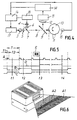
- the numerals 3 and 4 indicate two laser beam sources, for example constituted by solid-state diodes of the type commercially known by the code TOLD 9211 and manufactured by the Toshiba company (Japan).
- the beams at the output of the diodes are mutually perpendicular and are focused at different distances by respective optical assemblies 5 and 6.
- the beam arriving from the optical assembly 5 is sent through a semireflecting mirror 7 which is arranged at the intersection point of the beams and reflects the beam arriving from the assembly 6.
- the angles of incidence of the laser beams arriving from the optical assemblies 5, 6 with respect to the mirror 7 are chosen so as to generate a unidirectional beam 8 which is directed, through a hole of an optical receiver assembly 9, onto a polygonal rotor 10.
- the polygonal rotor 10 comprises a plurality of peripheral mirrors 11 which, by means of the rotation of the rotor 10, scan a preset read area.
- the beam reflected from the read area is deflected by said rotor and by the receiver assembly 9 toward an optical return system 12 and then to the input of a video amplifier 13 which provides to a microprocessor-based decoding unit 14 a signal which corresponds to the image of the area scanned by the laser beam.
- a rotation sensor 15 is operatively associated with the rotor 10 and provides, for each mirror 11 which passes in front of it, a signal which actuates a control device 16 which can alternately activate the power supplies 17, 18 of the two diodes 3 and 4.
- the signals supplied by the sensor 15 occur in the form of pulses A which are emitted at regular intervals in the period of transition between one mirror and the subsequent one during the rotation of the rotor 10.
- the control device 16 alternatively activates, upon each pulse A arriving from the sensor 15, the power supplies 17, 18 of the two laser diodes 3 and 4 if the scanning of the read area has not detected the presence of a code. Vice versa, if the scanning determines the presence of a code, the control device 16 keeps active the power supply of the diode which has produced the laser beam which has identified the code.
- the power supply 17 receives a level "1" signal, with the corresponding switching on of the diode 3 for the period T, the power supply 18 receives a level "0" signal which keeps the diode 4 switched off for the same period T.
- the duration T1 of the pulses is used to complete the switching of the diodes, and no scanning of the read area is performed during this time.
- the read area is scanned by the laser beam emitted by the diode 3, 4 which is connected to the power supply which receives, at that instant, the level "1" signal from the control device; the other power supply is blocked by the level "0" signal.
- the signal sent to the power supply 17 is indicated by B and the one sent to the power supply 18 is indicated by C.
- the alternation of the signals B and C is controlled by the signal D at the output of the decoding unit 14, which can assume two levels, "1" and "0", depending on whether the presence of a bar code in the read area is detected or not.
- the rotor 10 by means of the sensor 15, is synchronized with the power supplies 17, 18, so that each mirror of the rotor reflects onto the region to be scanned the laser beam emitted by the power supply which has received the level "1" signal at that instant. Since the laser beams emitted by the diodes 3, 4 are focused on two different areas A1 and A2 (see figure 6), the alternation in emission also produces the alternation in the scanning of the two regions A1 and A2 which compose the read area.
- the signal B of the power supply 17 is at level "0" and therefore the diode 3 is off, whereas the signal C of the power supply is at level "1" and therefore the diode 4 is on, so that the region A2, on which the beam emitted by the diode 4 is focused, is scanned.
- the image of the scanning area is reflected in each instance by the optical assembly 9 and sent to the decoding unit 14, and when said decoding unit identifies a bar code E therein, the output signal D changes level, thus indicating, even before the code is decoded, the presence of a probable useful data item.
- the change in level of the signal D is interpreted by the control device 16 as a command for locking the power supplies 17, 18 in the state in which they are at that instant.
- the change in level from "0" to "1" of the signal D causes the locking of the signal B at level "0" and of the signal C at level "1", so that the subsequent scans are performed by the same laser beam, in this case by the beam emitted by the diode 4, which is focused in the region A2 explored thereby, where the presence of the code has been detected.
- the signal D returns to level "0", restoring the alternating scan.
- the described reader perfectly achieves the intended aim.
- the cyclic scanning of the regions which compose the read area with laser beams, each of which is focused on a respective region allows a high read probability.
- the number of laser sources can be higher than two, so as to include a larger read area.
- a further variated embodiment provides the driving of the power supplies on the part of an external sensor which can detect the presence of the code.
- the signal D is no longer necessary, since switching from one power supply to the other is controlled by the external sensor.
- Another possibility provides the continuous switching of the reading from region A1 to region A2, regardless of the presence of the code. In this case a simpler electronic circuitry is obtained, but half of the scans cannot be used since they are performed on an area in which the code is not present.
Landscapes
- Physics & Mathematics (AREA)
- Engineering & Computer Science (AREA)
- Electromagnetism (AREA)
- Artificial Intelligence (AREA)
- Toxicology (AREA)
- General Health & Medical Sciences (AREA)
- Health & Medical Sciences (AREA)
- Computer Vision & Pattern Recognition (AREA)
- General Physics & Mathematics (AREA)
- Theoretical Computer Science (AREA)
- Mechanical Optical Scanning Systems (AREA)
- Liquid Crystal (AREA)
- Electrical Discharge Machining, Electrochemical Machining, And Combined Machining (AREA)
Claims (9)
- Lecteur de code-barres à rayons laser comprenant : au moins deux sources de rayon laser (3, 4) ; des moyens d'alimentation en courant (17, 18) pour permettre auxdites sources (3, 4) d'émettre des rayons laser respectifs ; des moyens de focalisation optiques (5-6) adaptés pour focaliser les rayons émis, des moyens optiques (7-12) pour diriger les rayons focalisés sur des zones lues (A1, A2) et pour diriger les rayons réfléchis depuis lesdites zones (A1, A2) vers des moyens de traitement (14) ;
caractérisé en ce que des moyens de commande électriques (16) sont prévus qui sont adaptés pour activer en alternance les moyens d'alimentation en courant (17, 18) pour émettre lesdits rayons laser de manière périodique et avec une alternance cyclique, et en ce que chacun desdits rayons laser est focalisé par les moyens de focalisation optiques (5-6) sur les zones lues (A1, A2) définies à des distances différentes préétablies à partir du lecteur de code-barres à rayons laser suivant sensiblement le même chemin de balayage. - Lecteur à rayons laser selon la revendication 1, caractérisé en ce que des moyens formant circuit électronique sont prévus qui, lorsque les moyens de traitement (14) détectent la présence d'un code-barres (E) dans l'une desdites zones lues (A1, A2), actionnent sélectivement lesdits moyens de commande électriques (16) de manière à ce qu'ils activent uniquement la source (3, 4) qui émet le rayon qui est focalisé sur ladite zone (A1, A2) et à ce qu'ils désactivent les sources restantes (3, 4).
- Lecteur à rayons laser selon la revendication 1, caractérisé en ce que lesdits moyens optiques (7-12) sont adaptés pour superposer les rayons émis par lesdites sources (3, 4) et focalisés à différentes distances du lecteur de code-barres à rayons laser, de manière à générer un rayon unidirectionnel (8).
- Lecteur à rayons laser selon la revendication 3, caractérisé en ce que lesdits rayons se croisent et en ce que lesdits moyens optiques (7-12) comprennent un miroir semi-argenté (7), agencé au point d'intersection des rayons, de sorte que l'un desdits rayons soit réfléchi et que l'autre passe à travers le miroir semi-argenté (7), les angles d'incidence desdits rayons sur le miroir (7) étant choisis de manière à générer ledit rayon unidirectionnel (8).
- Lecteur à rayons laser selon la revendication 3, caractérisé en ce que lesdits moyens optiques (7-12) comprennent un ensemble formant récepteur (9) muni d'un trou à travers lequel est guidé ledit rayon unidirectionnel (8), un rotor polygonal (10) étant agencé après ledit ensemble formant récepteur (9) pour dévier ledit rayon unidirectionnel (8) sur l'une desdites zones lues (A1, A2) de manière à effectuer le balayage de celles-ci.
- Lecteur à rayons laser selon la revendication 5, caractérisé en ce que ledit ensemble formant récepteur (9) est adapté pour diriger le rayon réfléchi depuis lesdites zones lues (A1, A2) vers un amplificateur vidéo (13) qui est adapté pour fournir un signal, qui corresponde à l'image de la zone balayée, à une unité (14) de décodage dudit signal.
- Lecteur à rayons laser selon la revendication 6, caractérisé en ce que lesdits moyens de commande électriques (16) sont commandés par ladite unité de décodage (14) et par un détecteur de rotation (15) associé de manière opérationnelle au rotor (10), de sorte que lorsque l'unité de décodage (14) ne détecte pas la présence d'un code-barres (E) dans les zones lues (A1, A2), les moyens de commande électriques (16) sont activés par le détecteur de rotation (15) de manière à activer en alternance les sources de rayon laser (3, 4) et ainsi balayer en alternance les zones lues (A1, A2), tandis que lorsque l'unité de décodage (14) détecte la présence d'un code-barres (E) dans les zones lues (A1, A2), les moyens de commande électriques (16) n'activent que la source (3, 4) du rayon laser qui est focalisé sur la zone lue (A1, A2) dans laquelle le code-barres (E) est présent.
- Lecteur à rayons laser selon la revendication 1, caractérisé en ce que lesdites sources de rayon laser (3, 4) comprennent une diode à semi-conducteur.
- Lecteur à rayons laser selon la revendication 1, caractérisé en ce qu'il comprend en outre un détecteur externe adapté pour détecter la présence d'un code-barres (E) sur un objet de manière à activer la source (3, 4) du rayon laser qui est focalisé sur la zone lue (A1, A2) où le code-barres (E) est présent pour toute la durée pendant laquelle l'objet reste à l'intérieur de la zone lue (A1, A2).
Applications Claiming Priority (2)
| Application Number | Priority Date | Filing Date | Title |
|---|---|---|---|
| IT367990 | 1990-10-09 | ||
| IT00367990A IT1242584B (it) | 1990-10-09 | 1990-10-09 | Lettore di codici a barre a raggio laser. |
Publications (2)
| Publication Number | Publication Date |
|---|---|
| EP0480348A1 EP0480348A1 (fr) | 1992-04-15 |
| EP0480348B1 true EP0480348B1 (fr) | 1997-01-08 |
Family
ID=11111349
Family Applications (1)
| Application Number | Title | Priority Date | Filing Date |
|---|---|---|---|
| EP91117038A Expired - Lifetime EP0480348B1 (fr) | 1990-10-09 | 1991-10-07 | Lecteur à rayon laser de code à barres |
Country Status (4)
| Country | Link |
|---|---|
| US (2) | US5446267A (fr) |
| EP (1) | EP0480348B1 (fr) |
| DE (1) | DE69124052T2 (fr) |
| IT (1) | IT1242584B (fr) |
Families Citing this family (17)
| Publication number | Priority date | Publication date | Assignee | Title |
|---|---|---|---|---|
| US5258605A (en) * | 1990-03-13 | 1993-11-02 | Symbol Technologies, Inc. | Scan generators for bar code reader using linear array of lasers |
| CA2056272C (fr) * | 1991-06-14 | 2001-10-16 | Patrick Salatto, Jr. | Dispositif de balayage laser a plages combinees |
| DE4227003C1 (de) * | 1992-08-14 | 1993-11-25 | Leuze Electronic Gmbh & Co | Optische Abtasteinrichtung zum Lesen von Strichcodesymbolen |
| IT1264733B1 (it) * | 1993-11-04 | 1996-10-04 | Datalogic Spa | Dispositivo di lettura o scanner a laser per la lettura di caratteri aventi un diverso grado di riflettenza, in particolare di codici a |
| US5979769A (en) * | 1996-11-05 | 1999-11-09 | Psc Inc. | Combination range laser scanner utilizing periodic range switching |
| NL1006454C2 (nl) * | 1997-07-02 | 1999-02-15 | Scantech Bv | Inrichting en werkwijze voor het lezen van een code op een artikel. |
| DE69704782T2 (de) | 1997-12-16 | 2002-03-07 | Datalogic S.P.A., Lippo Di Calderara Di Reno | Optischer Codeabtaster mit sich entlang zwei unterschiedlichen optischen Wegen bewegenden Laserstrahlen |
| DE29811486U1 (de) | 1998-06-26 | 1998-10-08 | Sick AG, 79183 Waldkirch | Optoelektronischer Sensor |
| US6536672B1 (en) | 1998-11-18 | 2003-03-25 | Dna Technologies, Inc. | Product authentication system and method |
| US6354501B1 (en) * | 1998-11-18 | 2002-03-12 | Crossoff Incorporated | Composite authentication mark and system and method for reading the same |
| US6137967A (en) | 1999-09-13 | 2000-10-24 | Oce Printing Systems Gmbh | Document verification and tracking system for printed material |
| EP1437676B1 (fr) * | 2002-12-31 | 2007-10-24 | Datalogic S.P.A. | Méthode de lecture d'un motif graphique et d'acqusition de son image |
| DE10331467A1 (de) * | 2003-07-11 | 2005-02-10 | Sick Ag | Vorrichtung zum optischen Abtasten von Objekten, insbesondere von Markierungen |
| US8316068B2 (en) | 2004-06-04 | 2012-11-20 | Telefonaktiebolaget Lm Ericsson (Publ) | Memory compression |
| US8459557B2 (en) * | 2011-03-10 | 2013-06-11 | Metrologic Instruments, Inc. | Dual laser scanning code symbol reading system employing automatic object presence detector for automatic laser source selection |
| US9530037B1 (en) | 2015-07-20 | 2016-12-27 | Datalogic ADC, Inc. | Toggling activation of lasers in scanner systems |
| USD802593S1 (en) * | 2015-08-28 | 2017-11-14 | Hand Held Products, Inc. | Scanner |
Family Cites Families (8)
| Publication number | Priority date | Publication date | Assignee | Title |
|---|---|---|---|---|
| JPS54132131A (en) * | 1978-04-05 | 1979-10-13 | Sumitomo Electric Ind Ltd | Optical information reading device |
| SE433783B (sv) * | 1982-03-03 | 1984-06-12 | Pharos Ab | Optisk svepanordning |
| DE3311352C1 (de) * | 1983-03-29 | 1984-03-15 | Ingenieurbüro Rudolf Weber KG, 6100 Darmstadt | Detektor zur Registrierung von Marken |
| US4704519A (en) * | 1986-06-19 | 1987-11-03 | Emhart Industries, Inc. | Selective code reader |
| CA1325473C (fr) * | 1988-09-20 | 1993-12-21 | Yasuhisa Yamashita | Appareil de lecture optique |
| JP2732497B2 (ja) * | 1988-09-21 | 1998-03-30 | 株式会社テック | 商品データ読取装置 |
| US5552590A (en) * | 1992-09-08 | 1996-09-03 | Nippondenso Co., Ltd. | Optical information reading apparatus having means for judging laser deterioration |
| IT1264733B1 (it) * | 1993-11-04 | 1996-10-04 | Datalogic Spa | Dispositivo di lettura o scanner a laser per la lettura di caratteri aventi un diverso grado di riflettenza, in particolare di codici a |
-
1990
- 1990-10-09 IT IT00367990A patent/IT1242584B/it active IP Right Grant
-
1991
- 1991-10-07 EP EP91117038A patent/EP0480348B1/fr not_active Expired - Lifetime
- 1991-10-07 DE DE69124052T patent/DE69124052T2/de not_active Expired - Lifetime
-
1994
- 1994-02-03 US US08/191,241 patent/US5446267A/en not_active Expired - Lifetime
-
1997
- 1997-08-29 US US08/921,045 patent/USRE37017E1/en not_active Expired - Lifetime
Also Published As
| Publication number | Publication date |
|---|---|
| EP0480348A1 (fr) | 1992-04-15 |
| USRE37017E1 (en) | 2001-01-16 |
| US5446267A (en) | 1995-08-29 |
| IT1242584B (it) | 1994-05-16 |
| IT9003679A0 (it) | 1990-10-09 |
| DE69124052D1 (de) | 1997-02-20 |
| IT9003679A1 (it) | 1992-04-09 |
| DE69124052T2 (de) | 1997-05-22 |
Similar Documents
| Publication | Publication Date | Title |
|---|---|---|
| EP0480348A1 (fr) | Lecteur à rayon laser de code à barres | |
| US5216230A (en) | Laser beam scanner | |
| KR100247145B1 (ko) | 공간 광 변조기 레이저 도트 스캐너 및 스캐닝 방법 | |
| US5663549A (en) | System for reading a symbol by activitating a liquid crystal device to control a scanning path | |
| US5648650A (en) | Optical bar code reading apparatus with regular reflection detecting circuit | |
| CA2056272C (fr) | Dispositif de balayage laser a plages combinees | |
| US6065678A (en) | Bar code scanner having a focusing system | |
| EP0652530B1 (fr) | Scanner à laser et méthode de lecture d'un code optique sur un objet | |
| US4916297A (en) | Code reader | |
| KR100209781B1 (ko) | 발광다이오드 주사장치 | |
| US5777310A (en) | Problem reduction with low level information integration in bar code decoding | |
| JP2737143B2 (ja) | バーコード読取装置 | |
| EP0752680A1 (fr) | Scanner optique avec des éléments optiques avec deux surfaces pour deux rayons d'action | |
| US5484990A (en) | Multiple depth of field laser optical scanner | |
| US5448078A (en) | Bar code or optical data reader which adjusts focal length based on detected distance to coded surface | |
| EP0848344B1 (fr) | Appareil de balayage d'un code optique se trouvant sur un article en mouvement et méthode de balayage d'un tel code optique par moyen d'un tel appareil de balayage | |
| KR100402341B1 (ko) | 광학식 기호 판독 장치 | |
| JPH02136984A (ja) | レーザースキヤナ | |
| JP2971493B2 (ja) | バーコード読み取り装置 | |
| JP4099854B2 (ja) | バーコード読取装置 | |
| JPH02133891A (ja) | バーコードスキャナー | |
| US20050269413A1 (en) | Bar code scanner with laser beam oscillator | |
| JP3104455B2 (ja) | 光学的情報読取装置 | |
| JP2904556B2 (ja) | レーザ加工装置 | |
| JP3067415B2 (ja) | 光学式読取装置 |
Legal Events
| Date | Code | Title | Description |
|---|---|---|---|
| PUAI | Public reference made under article 153(3) epc to a published international application that has entered the european phase |
Free format text: ORIGINAL CODE: 0009012 |
|
| AK | Designated contracting states |
Kind code of ref document: A1 Designated state(s): DE FR GB SE |
|
| 17P | Request for examination filed |
Effective date: 19920923 |
|
| 17Q | First examination report despatched |
Effective date: 19950405 |
|
| GRAH | Despatch of communication of intention to grant a patent |
Free format text: ORIGINAL CODE: EPIDOS IGRA |
|
| GRAH | Despatch of communication of intention to grant a patent |
Free format text: ORIGINAL CODE: EPIDOS IGRA |
|
| GRAH | Despatch of communication of intention to grant a patent |
Free format text: ORIGINAL CODE: EPIDOS IGRA |
|
| GRAA | (expected) grant |
Free format text: ORIGINAL CODE: 0009210 |
|
| AK | Designated contracting states |
Kind code of ref document: B1 Designated state(s): DE FR GB SE |
|
| REF | Corresponds to: |
Ref document number: 69124052 Country of ref document: DE Date of ref document: 19970220 |
|
| ET | Fr: translation filed | ||
| PLBE | No opposition filed within time limit |
Free format text: ORIGINAL CODE: 0009261 |
|
| 26N | No opposition filed | ||
| REG | Reference to a national code |
Ref country code: GB Ref legal event code: IF02 |
|
| REG | Reference to a national code |
Ref country code: GB Ref legal event code: 732E |
|
| REG | Reference to a national code |
Ref country code: GB Ref legal event code: 732E |
|
| REG | Reference to a national code |
Ref country code: FR Ref legal event code: TP Ref country code: FR Ref legal event code: CD |
|
| PGFP | Annual fee paid to national office [announced via postgrant information from national office to epo] |
Ref country code: GB Payment date: 20090928 Year of fee payment: 19 Ref country code: SE Payment date: 20090924 Year of fee payment: 19 |
|
| PGFP | Annual fee paid to national office [announced via postgrant information from national office to epo] |
Ref country code: DE Payment date: 20091118 Year of fee payment: 19 |
|
| PGFP | Annual fee paid to national office [announced via postgrant information from national office to epo] |
Ref country code: FR Payment date: 20091201 Year of fee payment: 19 |
|
| GBPC | Gb: european patent ceased through non-payment of renewal fee |
Effective date: 20101007 |
|
| PG25 | Lapsed in a contracting state [announced via postgrant information from national office to epo] |
Ref country code: FR Free format text: LAPSE BECAUSE OF NON-PAYMENT OF DUE FEES Effective date: 20101102 |
|
| REG | Reference to a national code |
Ref country code: FR Ref legal event code: ST Effective date: 20110630 |
|
| PG25 | Lapsed in a contracting state [announced via postgrant information from national office to epo] |
Ref country code: GB Free format text: LAPSE BECAUSE OF NON-PAYMENT OF DUE FEES Effective date: 20101007 |
|
| REG | Reference to a national code |
Ref country code: DE Ref legal event code: R119 Ref document number: 69124052 Country of ref document: DE Effective date: 20110502 |
|
| PG25 | Lapsed in a contracting state [announced via postgrant information from national office to epo] |
Ref country code: SE Free format text: LAPSE BECAUSE OF NON-PAYMENT OF DUE FEES Effective date: 20101008 |
|
| PG25 | Lapsed in a contracting state [announced via postgrant information from national office to epo] |
Ref country code: DE Free format text: LAPSE BECAUSE OF NON-PAYMENT OF DUE FEES Effective date: 20110502 |