EP0480429B1 - Jalousieaufzieh- und Wendemechanismus - Google Patents
Jalousieaufzieh- und Wendemechanismus Download PDFInfo
- Publication number
- EP0480429B1 EP0480429B1 EP91117305A EP91117305A EP0480429B1 EP 0480429 B1 EP0480429 B1 EP 0480429B1 EP 91117305 A EP91117305 A EP 91117305A EP 91117305 A EP91117305 A EP 91117305A EP 0480429 B1 EP0480429 B1 EP 0480429B1
- Authority
- EP
- European Patent Office
- Prior art keywords
- ladder
- ring
- drum
- cords
- lifting
- Prior art date
- Legal status (The legal status is an assumption and is not a legal conclusion. Google has not performed a legal analysis and makes no representation as to the accuracy of the status listed.)
- Expired - Lifetime
Links
Images


Classifications
-
- E—FIXED CONSTRUCTIONS
- E06—DOORS, WINDOWS, SHUTTERS, OR ROLLER BLINDS IN GENERAL; LADDERS
- E06B—FIXED OR MOVABLE CLOSURES FOR OPENINGS IN BUILDINGS, VEHICLES, FENCES OR LIKE ENCLOSURES IN GENERAL, e.g. DOORS, WINDOWS, BLINDS, GATES
- E06B9/00—Screening or protective devices for wall or similar openings, with or without operating or securing mechanisms; Closures of similar construction
- E06B9/24—Screens or other constructions affording protection against light, especially against sunshine; Similar screens for privacy or appearance; Slat blinds
- E06B9/26—Lamellar or like blinds, e.g. venetian blinds
- E06B9/28—Lamellar or like blinds, e.g. venetian blinds with horizontal lamellae, e.g. non-liftable
- E06B9/30—Lamellar or like blinds, e.g. venetian blinds with horizontal lamellae, e.g. non-liftable liftable
- E06B9/303—Lamellar or like blinds, e.g. venetian blinds with horizontal lamellae, e.g. non-liftable liftable with ladder-tape
- E06B9/307—Details of tilting bars and their operation
-
- E—FIXED CONSTRUCTIONS
- E06—DOORS, WINDOWS, SHUTTERS, OR ROLLER BLINDS IN GENERAL; LADDERS
- E06B—FIXED OR MOVABLE CLOSURES FOR OPENINGS IN BUILDINGS, VEHICLES, FENCES OR LIKE ENCLOSURES IN GENERAL, e.g. DOORS, WINDOWS, BLINDS, GATES
- E06B9/00—Screening or protective devices for wall or similar openings, with or without operating or securing mechanisms; Closures of similar construction
- E06B9/24—Screens or other constructions affording protection against light, especially against sunshine; Similar screens for privacy or appearance; Slat blinds
- E06B9/26—Lamellar or like blinds, e.g. venetian blinds
- E06B9/28—Lamellar or like blinds, e.g. venetian blinds with horizontal lamellae, e.g. non-liftable
- E06B9/30—Lamellar or like blinds, e.g. venetian blinds with horizontal lamellae, e.g. non-liftable liftable
- E06B9/32—Operating, guiding, or securing devices therefor
- E06B9/322—Details of operating devices, e.g. pulleys, brakes, spring drums, drives
-
- E—FIXED CONSTRUCTIONS
- E06—DOORS, WINDOWS, SHUTTERS, OR ROLLER BLINDS IN GENERAL; LADDERS
- E06B—FIXED OR MOVABLE CLOSURES FOR OPENINGS IN BUILDINGS, VEHICLES, FENCES OR LIKE ENCLOSURES IN GENERAL, e.g. DOORS, WINDOWS, BLINDS, GATES
- E06B9/00—Screening or protective devices for wall or similar openings, with or without operating or securing mechanisms; Closures of similar construction
- E06B9/24—Screens or other constructions affording protection against light, especially against sunshine; Similar screens for privacy or appearance; Slat blinds
- E06B9/26—Lamellar or like blinds, e.g. venetian blinds
- E06B9/28—Lamellar or like blinds, e.g. venetian blinds with horizontal lamellae, e.g. non-liftable
- E06B9/30—Lamellar or like blinds, e.g. venetian blinds with horizontal lamellae, e.g. non-liftable liftable
- E06B9/32—Operating, guiding, or securing devices therefor
- E06B9/322—Details of operating devices, e.g. pulleys, brakes, spring drums, drives
- E06B2009/3225—Arrangements to aid the winding of cords rollers
Definitions
- the present invention relates to a venetian blind including an apparatus for lifting and tilting slats of a slat-ladder according to the preamble of claim 1.
- Prior art apparatus for lifting and tilting slats of a slat-ladder in a venetian blind performs the tilting operation in a manner that: the ladder cords are respectively put on, and secured to, each of ladder rings, with the mid portion of the ladder cords positioned on the top of the ladder rings; each of the ladder rings is slippably fitted around each of ladder drums; the ladder drums are arranged to rotate together with a rotating shaft; then, when the shaft is rotated together with the ladder drums, the ladder rings first rotate together with the ladder drums, and thereby the ladder cords are moved together with the ladder drums around the shaft, with the front and the rear sides of the ladder cords shifted to the opposite directions with each other, so that the slats are tilted; when the slats are tilted to a limit, the ladder rings are arranged to engage with a stopper and do not rotate any further while starting slippage around the ladder drums, so that the ladder cords are no longer moved
- the prior art apparatus described above proceeds to the lifting operation following the end of the tilting operation described above, in a manner that: while the ladder cords stop moving and the tilting motion comes to an end, the lift cords, or tapes, continue to be lifted or lowered so as to lift or lower the ladder, as the shaft continues to be rotated together with lifting drums around which the lift cords are wound for lifting and rewound for lowering.
- the prior art apparatus described above is disclosed in Japanese Unexamined Utility Model Publication 63127596.
- US-patent No 2737235 relates to winding and adjusting means for use in Venetian blinds with adjustable slats having a winding shaft and winding drums tightly mounted on the latter, for the pull tapes of the blind.
- the disclosed mechanism comprises a ratchet wheel disposed on, and constituting a part of, a lifting drum cover which rotates together with the shaft, and a pawl disposed on a holder fixed to a head box so that the pawl may have a rocking motion in the radial direction of the ratchet wheel.
- the pawl is arranged so that the pawl is normally pressed on, and engaged with, the ratchet wheel, by a spring, and the lift cord is arranged to pass around the pawl.
- the lifting drum cover is largest in its width from the front to the rear, or outdoor, sides.
- the shaft rotation stopping mechanism of the prior art apparatus has a disadvantage in that, since the radially protruding ratchet wheel is disposed around the circumference of the lifting drum cover, and the pawl, radially engaging with the ratchet wheel, is disposed on the holder, the width from the front to the rear sides and the height, of the head box are relatively large in their sizes.
- the lift cords, hanging down from the head box are typically aligned with the ladder cords respectively in line from the front to the rear sides.
- This alignment has been accomplished in conventional venetian blinds by an arrangement in which the ladder cords, respectively put on, and secured to, each of the ladder rings, hang downward directly from the secured positions on the ladder rings, while the lift cords are pulled around to the positions where the ladder cords hang downward.
- the arrangement for the lift cords and the ladder cords, described above, was selected because an alternative, or opposite arrangement has a certain problem.
- the alternative arrangement is that the lift cords hang downward directly from the lifting drum, while the ladder cords are pulled around to the positions where the lift cords hang downward.
- the certain problem, described above, with the alternative arrangement is that the lifting and lowering movements of the slats are significantly heavy, or unsmooth, because the fitting tightness between the ladder rings and the ladder drums of prior apparatus, is arranged to be always constant, while the resistance in the ladder cords becomes greater as they are pulled around, and subsequently, a tighter fitting is required between the ladder ring and the ladder drum for an unchanged lifting smoothness.
- the prior art apparatus for lifting and tilting slats of a slat-ladder for a venetian blind has an arrangement in which, the fitting tightness between the ladder rings and the ladder drums is arranged to be constant, as described above, and, in addition, the shaft is required to be further rotated to lift or lower the slat-ladder after the ladder ring is stopped by the stopper, following the slat tilting motion.
- the prior art apparatus for lifting and tilting slats has another disadvantage in that, in case where the fitting tightness between the ladder rings and the ladder drums is set tighter for a better slat tilting responsiveness, the frictional resistance between the ladder rings and the ladder drums becomes greater, whereby the ladder lifting and lowering motion becomes heavier and less smoother; and, in case where the fitting tightness between the ladder rings and the ladder drums is set looser for a lighter slat lifting and lowering motion, slat tilting responsiveness becomes poorer.
- the present invention is made to solve such problems.
- the venetian blind according to the present invention enables both of a better slat tilting responsiveness and a lighter slat lifting motion to occur with only a single apparatus.
- the venetian blind comprises: a head box; a rotating shaft; a first and a second ladder drums rotating together with the shaft; a first and a second drum holders for supporting the first and the second ladder drums; a first and a second ladder rings having an open ring shape and fitted around each of the first and second ladder drums; ladder cords being respectively put on, and secured to, each of the first and second ladder rings; lifting drums; lift cords, wound around each of the lifting drums; slats, supported by the ladder cords; and means for stopping the rotation of said shaft.
- the means for stopping the rotation of the shaft comprises: a stopper holder, fixed on a head box; a drum stopper of a ring shape, axially not slidably, but rotatably, attached to the stopper holder; a stop ring of a ring shape, axially slidably, but not rotatably, attached to the stopper holder; and a spring for axially pressing the stop ring against the drum stopper.
- the drum stopper and the stop ring have teeth respectively formed on the mutually opposite ends of the drum stopper and the stop ring so that the teeth are engageable with each other.
- the lifting drum is disposed through the inside of the drum stopper and the stop ring.
- the lifting drum has the drum stopper engaged therewith utilizing an axial slot thereof so that the drum stopper rotates together with the lifting drum.
- Each of the lift cords is put on the stop ring, and is hung downward.
- the first and second ladder rings respectively have a release ring disposed to be adjacent thereto.
- the release ring is loosely fitted around each of the first and second ladder drums.
- the release ring has an axial protrusion and an outward protrusion from the outer circumference thereof, respectively disposed thereon.
- the first and second drum holders have first and second stoppers respectively disposed thereon so that the first and second stoppers respectively limit the range of rotation of the release ring by engaging with the outward protrusion of the release ring.
- the axial protrusion of the release ring is inserted in each ring opening of the first and second ladder rings.
- the ladder rings are fitted to the ladder drums relatively tightly. In the case where a lifting drum cover is used, the ladder ring may be formed on one end of the lifting drum cover.
- the means, or mechanism, for stopping the rotation of the rotating shaft when any of the lift cords is slackened comprises: a stopper holder, fixed on a head box; a ring-shaped drum stopper rotating together with the lifting drum , and axially not slidably, but rotatably, attached to the stopper holder; a ring-shaped stop ring releasably engaging with the drum stopper, and axially slidably, but not rotatably, attached to the stopper holder; and a spring for axially pressing the stop ring against the drum stopper, the lift cords wound around the lifting drum being put on the stop ring, then hung downward, so that, in the case where the lift cord is tightened, the lift cord axially separates the stop ring from the drum stopper, resisting the spring force, and, in the case where the lift cord is slackened, the spring force presses the stop ring into an engagement with the
- the drum stopper or the stop ring to have a greater width from the front to the rear sides than the width of the lifting drum cover of prior mechanism.
- the width of the head cover from the front to the rear sides is smaller in comparison with the prior mechanism having a ratchet wheel with a diameter greater than the lifting drum cover, whereby, a better appearance and less restrictions for the installation space are obtained, as significant advantages.
- the apparatus performs the tilting, and lifting or lowering motions in a fashion that: as far as the slats are within an allowable range of tilting, the ladder rings are tightly fitted around the ladder drums; once the slats reach the tilting limit, the axial protrusions of the release rings, inserted in each ring opening of the ladder rings, forces the ladder ring to open so that the fitting tightness between the ladder rings and the ladder drums becomes looser.
- the apparatus effects another set of significant advantages including: a better tilting responsiveness to the rotating motion of the shaft due to a tighter fitting between the ladder rings and the ladder drums during the tilting; and a lighter lifting and lowering motion due to a looser fitting between the ladder rings and the ladder drums during the lifting and lowering.
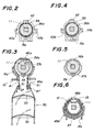
- a rotating shaft 11 having a square-shaped cross-section is disposed through in a head box 10 in the longitudinal direction.
- the rotating shaft 11 is rotatably driven by hand or a motor.
- a first and a second ladder drums 36a, 36b are fitted along and around the shaft 11 so as to rotate together with the shaft 11.
- the ladder drums are supported by a first and a second drum holders 15a, 15b, which are fixed to the head box 10.
- a first ladder ring 37a having an open ring shape, and a release ring 38, are respectively fitted around the first ladder drum 36a. The fitting tightness is relatively tight for the first ladder ring 37a, and relatively loose for the release ring 38.
- the release ring 38 has an axial protrusion 39 disposed thereon and inserted in the opening of the first ladder ring 37a.
- the first ladder ring 37a has a first fixture 46a of a first auxiliary ladder cord 45a secured to the top center of the first ladder ring 37a. Both ends of the first auxiliary ladder cord 45a run along the front and the rear side surfaces of the first ladder ring 37a, then, hang downward from a first opening frame 41 of the first drum holder 15a which protrudes from the bottom of the head box 10.
- a release ring 38, and a second ladder ring 37b formed on one end of a lifting drum cover 35 are respectively fitted around the second ladder drum 36b.
- the fitting tightness is relatively tight for the first ladder ring 37b, and relatively loose for the release ring 38.
- the release ring 38 has an axial protrusion 39 disposed thereon and inserted in the opening of the second ladder ring 37b.
- the lifting drum cover 35 extends axially from the one end to the other end, where the fixture 46b of a second auxiliary ladder cord 45b is secured via a slit.
- a drum washer 55 is disposed adjacent to the second auxiliary ladder cord 45b.
- the other end of the second drum holder 15b is disposed adjacent to the drum washer 55.
- Female screw threads 14 are formed on the other end of the second drum holder 15b to engage with male screw threads 13 of the lifting drum 12.
- Both ends of the second auxiliary ladder cord 45b are pulled around, in a manner to be described later, then, hang downward from a second opening frame 27, of a stopper holder 16, which protrudes from the bottom of the head box 10.
- Connectors 47 are respectively attached integral to the both ends of the auxiliary ladder cords 45a, 45b.
- Loops 51 disposed at the upper end on the front and the rear sides of main ladder cords 50, are connected to the connectors 47.
- the main ladder cords 50 support the slats 30 via wefts which constitute the ladder.
- a bottom rail which constitutes the slat of the lowest stage, is hung by the lift cords 28.
- the stopper holder 16 is fixed to the head box, adjacent to the other end of the second drum holder 15b.
- a drum stopper 17 and a stop ring 18 are attached to the stopper holder 16, through which the shaft 11 and the lifting drum 12 are disposed.
- the drum stopper 17 is arranged to be rotatable together with the lifting drum 12, but not axially slidable.
- the stop ring 18 is arranged to be not rotatable, but axially slidable.
- the stop ring 18 is pressed against the drum stopper 17 by the force of a spring 23 (FIG. 13).
- the lift cord 28, wound around the lifting drum 12, is put on a tail 21 of the stop ring 18, then, hangs downward below the head box 10 from the second opening frame 27 of the stopper holder 16, and reaches the bottom rail which constitutes the slat of the lowest stage.
- the stop ring 18 is separated from the drum stopper 17, and, subsequently, the lifting drum 12 rotates together with the shaft 11.
- the stop ring 18 engages with the drum stopper 17, and, subsequently, the rotation of the lifting drum 12 and the shaft 11 is blocked.
- the second auxiliary ladder cord 45b is put on, and secured via the second fixture 46b to, between the other end of the lifting drum cover 35 and the drum washer 55.
- the both ends of the second auxiliary ladder cord 45b run, along a guide groove 57 of the lifting drum cover 35 and guide grooves 56 of the drum holder 15b, into the stopper holder 16, then, hang downward below the head box 10 from the second opening frame 27 of the stopper holder 16, so as to be aligned with the lift cords 28, respectively in line, from the front to the rear sides.
- the release rings 38 also rotate together with the ladder rings 37a, 37b, and the shaft 11, since the release rings 38 have the axial protrusions thereof inserted in the opening of the ladder rings 37a, 37b.
- the release rings 38 can only rotate, or turn, for a range limited by the stoppers 43a or 43b where the outward protrusions 42 of the release rings 38 are respectively engaged and stopped.
- the rotational limits are set at 90 degrees each, either to the front side, and to the rear side.
- the axial protrusions 39, of the release rings 38 which are inserted in the opening of the ladder rings 37a, 37b, not only block the rotation of the ladder rings 37a and 37b, and the lifting drum cover 35, but also force the ring portion of the ladder rings 37a, 37b, to open wider, thereby loosening the fitting tightness between the ladder rings 37a, 37b, and the ladder drums 36a, 36b.
- the tilting of the slats 30 also reaches the limit.
- the shaft 11 is further being rotated under the condition of this stage, in which the ladder rings 37a, 37b, are opened wider by the axial protrusion 39 so that the fitting tightness thereof with the ladder drums 36a, 36b is loosened.
- the frictional resistance between the ladder drums 36a, 36b, and the ladder rings 37a, 37b, is respectively reduced, whereby the shaft 11 and the lifting drum 12 can be rotated lightly for winding up or winding down the lift cords.
- the ladder rings 37a, 37b are tightly fitted to the ladder drums 36a, 36b, so that no slipping occurs therebetween, and, subsequently, the ladder rings 37a, 37b, substantially together with the ladder drums 36a, 36b.
- the ladder rings 37a, 37b are opened wider, and the fitting tightness thereof with the ladder drums 36a, 36b, is loosened, and, subsequently, the frictional resistance therebetween is reduced, as described above.
- the second ladder ring 37b on which the second auxiliary ladder cord 45b is put on, and secured, can be tightly fitted around the ladder drum 36b, regardless of the torque required for rotating the shaft 11 to lift and lower the slats.
- an arrangement as shown in FIG. 7, is obtained in which, while the lift cord 28 is hung directly from the lifting drum 28, the second auxiliary ladder cord 45b may be pulled around, along the guide groove 57 of the lifting drum cover 35 and the guide grooves 56 of the drum holder 15b, then, to the positions aligned with said lift cords 28, respectively in line, from the front to the rear sides.
- the fixture 46a is disposed in the central portion of the first auxiliary ladder cord 45a, which is equipped with connectors 47 on the both ends thereof.
- the fixture 46a has a plate shape, and has side protrusions 48 oppositely formed with each other.
- the fixture 46a corresponds to a flat portion 49 formed between flanges 44 on the top of the circumference of the first ladder ring 37a.
- Two retaining holes 52 are formed axially in line through the flange portions 44 at a position corresponding to the flat portion 49.
- the side protrusions 48 respectively fit in the retaining holes 52.
- the first ladder ring 37a is made of plastic material having elasticity, and the flanges 44 are formed to have a slant inside surface.
- the flanges 44 can be easily elastically opened, then, the fixture 46a is settled on the flat portion 49, and the side protrusions 48 are fitted in the retainig holes 52, by a pressing motion of the fixture 46a against the flat portion 49, with the side protrusions 48 held along the side flanges 44.
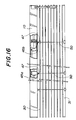
- FIG. 16 shows a front elevational general view of a venetian blind, equipped with the apparatus according to the present invention.
- the main ladder cords 50 are hung from the connectors 47 of the auxiliary ladder cords 45a, 45b, which hang from the head box 10.
- the main ladder cords 50 support all the slats 30, or slat-ladder, and the bottom rail 31.
- the assembling and disassembling of the main ladder cords 50 and the auxiliary ladder cords 45a, 45b is simple and easy.
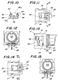
- an outer circumferential groove 19 of the drum stopper 17 is fitted to a semicircular protrusion 20 disposed on the stopper holder 16.
- the drum stopper 17 has an inner circumferential protrusion 33, which is fitted in an axial slot 34 disposed on the lifting drum 12, whereby the drum stopper 17 rotates together with the lifting drum 12.
- the stop ring 18 has a tail 21, as described above, which extends axially in the direction opposite to the drum stopper side. As shown in FIGs. 11 and 12, the tail 21 has a V-shaped slant groove 22 disposed thereon.
- One of the two sides of the slant groove 22 is arranged to be at a right angle with the direction in which the tail 21 extends, or the axial direction, while the other side constitutes a slant surface intersecting the right-angled side.
- the stop ring 18 is arranged to be slidable axially within a predetermined distance, while being not rotatable.
- spring 23 is disposed between the stop ring 18 and the stopper holder 16. The spring 23 axially presses the stop ring 18 against the drum stopper 17.
- the stopper holder 16 has opening frame 27 disposed to be fitted in a bottom opening 26 of the stopper holder 16.
- the tail 21 is positioned over the opening frame 27.
- the lift cord 28, wound on the lifting drum 12, is put on the slant groove 28, then, is hung downward via the opening frame 27. Since the slant groove 22 is formed so that the groove is shallow at the outermost point and deep at the innermost point, when the lift cord 28 is tightened by the load of the bottom rail 31, as shown in FIG. 1, the lift cord 28 pushes the slant groove 22, and, subsequently, the tail 21, axially to the right in FIG. 11, and as also shown in FIG. 12, resisting the force of the spring 23, so that the engaging teeth 24, 25 of the stop ring 18 and the drum stopper 17 are separated. Then, the drum stopper 17 rotates without restriction.
- the spring 23 presses the stop ring 18 against the drum stopper 17 so that the teethe 24, 25 are engaged again, whereby the rotation of the drum stopper 17 and the lifting drum 12, which is coupled with the drum stopper 17, and the shaft 11 is blocked.
- the lift cord 28 is moved in the direction vertical to the axial direction, by the slant groove 22 of the tail 21.
- the shaft rotation stopping mechanism there is no need to set the outer diameter, or the width from the front to the rear sides, of the drum stopper 17 and the stop ring 18, at a value greater than the lifting drum cover 35. Therefore, the inside width from the front to the rear sides of the head box may be only slightly greater than the outer diameter of the lifting drum cover 35.
- the head box 10 according to the present invention can be significantly reduced in the width from the front to the rear sides thereof, in comparison with the prior art in which a ratchet wheel is fitted around the lifting drum, and, subsequently, the inside dimension of the head box has to be greater than the outer diameter of the ratchet wheel.
Landscapes
- Engineering & Computer Science (AREA)
- Structural Engineering (AREA)
- Architecture (AREA)
- Civil Engineering (AREA)
- Blinds (AREA)
Claims (6)
- Jalousie mit einem Mechanismus zum Hochziehen und Wenden der Lamellen einer Lamellenleiter, aufweisend: einen Oberkasten (10); eine Welle (11), die im Oberkasten so angeordnet ist, daß sie drehbar angetrieben wird; eine erste und eine zweite Leitertrommel (36a, 36b), die entlang der Welle so angeordnet sind, daß sie sich zusammen mit der Welle drehen; einen ersten und einen zweiten Trommelhalter (15a, 15b), die am Oberkasten befestigt sind und jeweils entsprechend die erste und die zweite Leitertrommel tragen; einen ersten und einen zweiten Leiterring (37a, 37b), von denen jeder die Form eines offenen Ringes aufweist und jeweils entsprechend um die erste und um die zweite Leitertrommel montiert ist; Leiterschnüre (45a, 45b, 50), die jeweils entsprechend auf dem ersten und dem zweiten Leiterring montiert und daran befestigt sind; Hochziehtrommeln (12), die sich zusammen mit der Welle (11) drehen und bei denen der äußere Umfang derselben in den zweiten Trommelhalter (15b) eingeschraubt ist; Hochziehschnüre (28), die jeweils entsprechend um die Hochziehtrommeln gewickelt sind; Lamellen (30), die von den Leiterschnüren gehaltert werden; und Vorrichtungen zum Stoppen der Drehung der Welle im Falle, daß die Hochziehschnur entspannt wird;
dadurch gekennzeichnet, daß
die Einrichtungen zum Stoppen der Drehung der Welle aufweisen:einen Stopperhalter (16), der am Oberkasten befestigt ist;einen ringförmigen Trommelstopper (17), mit einem axial feststehenden, aber drehungsmäßig gleitbaren Anschluß an den Stopperhalter;einen Stoppring (18) mit einer Ringform, mit einem axial gleitbaren, aber drehungsmäßig feststehendem Anschluß an den Stopperhalter; und eine Feder (23) zum axialen Andrücken des Stoppringes gegen den Trommelstopper;wobei der Trommelstopper (17) und der Stoppring (18) gegenseitig in Eingriff bringbare Zähne (24, 25) aufweisen, die jeweils entsprechend auf den einander gegenüberliegenden Enden des Trommelstoppers und des Stoppringes gebildet sind;wobei die Hochziehtrommel (12) durch das Innere des Trommelstoppers und des Stoppringes hindurch angeordnet ist;wobei die Hochziehtrommel (12) und der Trommelstopper (17) gegenseitig über einen Vorsprung (20) und einen axialen Schlitz (19) in Eingriff stehen, so daß der Trommelstopper zusammen mit der Hochziehtrommel dreht;wobei jede der Hochziehschnüre (28) am Stoppring befestigt und an diesem nach unten hin aufgehängt ist, wodurch die Hochziehschnur, wenn sie stramm angezogen ist, den Stoppring (18) vom Trommelstopper (17) trennt und der Kraft der Feder (23) widersteht, und wodurch die Hochziehschnur, wenn sie entspannt wird, es der Feder ermöglicht, den Stoppring gegen den Trommelstopper zu drücken, um die Zähne (24, 25) miteinander in Eingriff zu bringen. - Jalousie mit einem Mechanismus nach Anspruch 1, dadurch gekennzeichnet, daß der zweite Leiterring (37b) so gestaltet ist, daß er einen Teil der Hochziehtrommelabdeckung (35) bildet.
- Jalousie mit einem Mechanismus nach Anspruch 2, dadurch gekennzeichnet, daß die Leiterschnüre jeweils erste Hilfsleiterschnüre (45a), zweite Hilfsleiterschnüre (45b) und Hauptleiterschnüre (50) umfassen, wobei die ersten und zweiten Hilfsleiterschnüre jeweils auf dem ersten Leiterring (37a) und der Hochziehtrommelabdeckung (35), die integral mit dem zweiten Leiterring (37b) ausgebildet ist, angebracht und daran befestigt sind, wobei die Hauptleiterschnüre (50) mit ihren oberen Enden an beide unteren Enden der ersten und der zweiten Hilfsleiterschnur (45a, 45b) an der Vorderseite und der Rückseite des Mechanismus unter dem Oberkasten (10) angeschlossen sind.
- Jalousie mit einem Mechanismus nach Anspruch 3, dadurch gekennzeichnet, daß die zweiten Hilfsleiterschnüre (45b), die auf der Hochziehtrommelabdeckung (35) aufgebracht und befestigt sind, welche integral mit dem zweiten Leiterring (37b) ausgebildet ist, entlang Führungsnuten (56) herumgewickelt sind, die auf dem zweiten Trommelhalter (15b) angebracht sind, so daß die zweiten Hilfsleiterschnüre (45b) vom Oberkasten (10) nach unten hängen, jeweils in der Ebene von der Vorderseite zur hinteren Seite ausgerichtet sind, wobei die Hochziehschnüre (28) direkt von der Hochziehtrommel (2) nach unten hängen.
- Jalousie mit einem Mechanismus nach Anspruch 3, dadurch gekennzeichnet, daß der zweite Leiterring (37a) zwei Flanschabschnitte (44) aufweist, die an beiden axialen Enden des Ringes gebildet sind, wobei der zweite Leiterring (37a) weiter einen sehnenartigen, horizontal flachen Abschnitt (49) aufweist, der auf dem oberen Bereich des Umfanges desselben gebildet ist, wobei der Flanschabschnitt zwei Rückhaltelöcher (51) aufweist, die axial in Übereinstimmung durch den Flachabschnitt hindurch in einer Position entsprechend dem flachen Abschnitt gebildet sind, wobei die ersten Hilfsleiterschnüre (45b) einen Kunststoffmittenbefestiger (46a) und Kunststoffanschlüsse (47) aufweisen, die jeweils entsprechend in der Mitte und an beiden Enden der Schnüre integral gebildet sind, wobei der Befestiger in einer Form ausgebildet ist, die in den flachen Abschnitt (49) der Leiterringe (37a) paßt, wobei der Befestiger (46a) seitliche Vorsprünge (48) aufweist, die einander gegenüberliegend und integral mit dem Befestiger ausgebildet sind, so daß die seitlichen Vorsprünge jeweils in die Rückhaltelöcher (52) passen.
- Jalousie mit einem Mechanismus nach Anspruch 1, dadurch gekennzeichnet, daß der erste und der zweite Leiterring (37a, 37b) jeweils einen Freigabering (38) aufweisen, der in ihrer Nähe angeordnet ist, wobei der Freigabering lose jeweils um die erste und um die zweite Leitertrommel (36a, 36b) montiert ist, wobei der Freigabering einen axialen Vorsprung (39) und einen vom äußeren Umfang des Ringes ausgehenden und darauf angeordneten Vorsprung (42) aufweist, wobei der erste und der zweite Trommelhalter (15a, 15b) jeweils entsprechend einen ersten und einen zweiten Stopper aufweisen, die auf ihnen so angeordnet sind, daß der erste und der zweite Stopper (43a, 43b) jeweils entsprechend den Drehbereich des Freigaberinges (38) durch Angreifen am nach außen gerichteten Vorsprung (42) des Freigaberinges (38) begrenzen, wobei der axiale Vorsprung (39) des Freigaberinges in jede Ringöffnung des ersten und des zweiten Leiterringes (37a, 37b) mit einer offenen Ringform eingefügt sind.
Applications Claiming Priority (8)
| Application Number | Priority Date | Filing Date | Title |
|---|---|---|---|
| JP105982/90 | 1990-04-20 | ||
| JP105982/90U | 1990-10-11 | ||
| JP105981/90U | 1990-10-11 | ||
| JP270432/90 | 1990-10-11 | ||
| JP105981/90 | 1990-10-11 | ||
| JP27043290A JP2816896B2 (ja) | 1990-10-11 | 1990-10-11 | 横型ブラインドのスラット傾動装置 |
| JP10598290U JP2557553Y2 (ja) | 1990-10-11 | 1990-10-11 | 横型ブラインドの補助コード装置 |
| JP10598190 | 1990-10-11 |
Publications (3)
| Publication Number | Publication Date |
|---|---|
| EP0480429A2 EP0480429A2 (de) | 1992-04-15 |
| EP0480429A3 EP0480429A3 (en) | 1993-05-05 |
| EP0480429B1 true EP0480429B1 (de) | 1997-03-19 |
Family
ID=27310624
Family Applications (1)
| Application Number | Title | Priority Date | Filing Date |
|---|---|---|---|
| EP91117305A Expired - Lifetime EP0480429B1 (de) | 1990-10-11 | 1991-10-10 | Jalousieaufzieh- und Wendemechanismus |
Country Status (5)
| Country | Link |
|---|---|
| US (1) | US5123472A (de) |
| EP (1) | EP0480429B1 (de) |
| KR (1) | KR920008309A (de) |
| DE (1) | DE69125238T2 (de) |
| ES (1) | ES2099113T3 (de) |
Cited By (2)
| Publication number | Priority date | Publication date | Assignee | Title |
|---|---|---|---|---|
| US9222302B2 (en) | 2013-12-27 | 2015-12-29 | Pella Corporation | Fenestration covering lift system and method |
| US9482046B2 (en) | 2013-12-27 | 2016-11-01 | Pella Corporation | Fenestration covering tilt system and method |
Families Citing this family (44)
| Publication number | Priority date | Publication date | Assignee | Title |
|---|---|---|---|---|
| CA2092300C (en) * | 1991-08-02 | 1996-04-02 | Edward T. Rude | Monocontrol venetian blind |
| US5228491A (en) * | 1992-04-03 | 1993-07-20 | General Clutch Corporation | Monocontrol venetian blind |
| US6068039A (en) * | 1992-09-28 | 2000-05-30 | Judkins; Ren | Material for venetian type blinds |
| US5573051A (en) * | 1995-02-06 | 1996-11-12 | Judkins; Ren | Venetian type blinds |
| EP0600133A1 (de) * | 1992-12-04 | 1994-06-08 | Nien Made Enterprise Co., Ltd. | Wendevorrichtung |
| US5318090A (en) * | 1993-05-11 | 1994-06-07 | Chen Cheng Hsiung | Roller assembly for venetian blind |
| US5553649A (en) * | 1993-07-05 | 1996-09-10 | Kabushiki Kaisha Nichibei | Blind apparatus |
| FR2718788B1 (fr) * | 1994-04-19 | 1996-05-15 | Ga | Dispositif de fin de course haute et basse de systèmes tels les stores motorisés. |
| FR2728933A1 (fr) * | 1995-01-04 | 1996-07-05 | Somfy | Dispositif d'enroulement de cordon de suspension de stores |
| US5806579A (en) * | 1995-02-06 | 1998-09-15 | Judkins; Ren | Venetian type blinds having opposed lift cords |
| US5839494A (en) * | 1995-02-06 | 1998-11-24 | Judkins; Ren | Bottom and top stacking venetian type blind with fixed headrail tilt |
| CA2213807C (en) * | 1995-03-06 | 2003-08-12 | Norbert Marocco | Combined tilt and raise control for window coverings |
| DE29615253U1 (de) * | 1996-09-02 | 1998-01-08 | Hüppe Form Sonnenschutz- und Raumtrennsysteme GmbH., 26133 Oldenburg | Wendeorgane für Rafflamellenjalousien oder Verbundraffstoren |
| US6032716A (en) * | 1997-02-13 | 2000-03-07 | Rollease, Inc. | Bottom stop mechanism for a window covering |
| US6648050B1 (en) | 1997-11-04 | 2003-11-18 | Andrew J. Toti | Spring drive system and window cover |
| US6244532B1 (en) | 1998-05-20 | 2001-06-12 | Btx Holdings, Inc. | System and apparatus for winding a lifting cord |
| US5906232A (en) * | 1998-06-10 | 1999-05-25 | Risk Analysis & Management | Window blind assembly |
| US6116323A (en) * | 1999-06-14 | 2000-09-12 | Huang; Shien-Te | Dual function dragging device for curtain |
| TW505189U (en) * | 2002-03-07 | 2002-10-01 | Ind Tech Res Inst | Plug-in transmission mechanism for a motor-driven blind |
| US7137430B2 (en) * | 2002-03-25 | 2006-11-21 | Rollease, Inc. | Mono control lift and tilt mechanism for horizontal blinds |
| US7066233B2 (en) * | 2002-07-22 | 2006-06-27 | Pella Corporation | Sliding operator for between the glass window coverings |
| WO2004009942A1 (en) * | 2002-07-22 | 2004-01-29 | Pella Corporation | Sliding operator for between the glass window coverings |
| US20060169418A1 (en) * | 2002-07-22 | 2006-08-03 | Pella Corporation | Window covering leveling method |
| DK1588011T3 (da) * | 2003-01-28 | 2007-09-03 | Vkr Holding As | Persienne |
| CN1795317B (zh) * | 2003-03-31 | 2012-02-01 | 约恩克拉布控股私人有限公司 | 活动百叶窗 |
| US6976522B2 (en) * | 2003-05-21 | 2005-12-20 | Springs Window Fashions Lp | Venetian blind ladder drum and method of assembling venetian blind |
| JP3965151B2 (ja) * | 2003-12-18 | 2007-08-29 | 立川ブラインド工業株式会社 | 日射遮蔽装置の障害物検知停止装置 |
| AT507095B1 (de) * | 2009-01-27 | 2010-02-15 | Kraler Franz | Antriebs- und wendevorrichtung für die lamellen einer jalousie |
| CH702333A1 (de) * | 2009-12-04 | 2011-06-15 | Griesser Holding Ag | Ganzmetall-Lamellenstore. |
| CN101886516B (zh) * | 2010-07-19 | 2012-11-28 | 浙江朗德实业有限公司 | 提升式百叶窗帘 |
| US9091115B2 (en) * | 2010-10-18 | 2015-07-28 | Qmotion Incorporated | Motorizable tilt shade system and method |
| CN102808577B (zh) * | 2012-07-30 | 2013-08-28 | 杭州欧卡索拉科技有限公司 | 百叶窗的卷轮机构及带齿轮离合器翻转机构的卷轮系统 |
| AU2012101508A4 (en) * | 2012-10-04 | 2012-11-08 | Acmeda Pty Ltd | Spindle cover |
| US9303451B2 (en) | 2013-02-25 | 2016-04-05 | Precision Coating Innovations, Llc | System for pivoting a blind slat |
| USD780480S1 (en) | 2013-02-25 | 2017-03-07 | Precision Coating Innovations, L.L.C. | Low profile blind head rail |
| US20140246156A1 (en) * | 2013-03-01 | 2014-09-04 | Aaron B. Dorny | Cord management for a window covering |
| US9963935B2 (en) | 2013-03-15 | 2018-05-08 | Hunter Douglas Inc. | Position lock for roller supported architectural coverings |
| US9078537B2 (en) * | 2013-06-05 | 2015-07-14 | Han-Sen Lee | Single cordless control for window covering |
| US9322210B2 (en) * | 2013-08-19 | 2016-04-26 | Comfortex Window Fashions | Cordless fabric venetian window shade assembly |
| KR101359513B1 (ko) | 2013-08-27 | 2014-02-07 | 곽재석 | 이중원단 블라인드의 원단 각도 조절장치 |
| CN205605050U (zh) | 2016-01-22 | 2016-09-28 | 亿丰综合工业股份有限公司 | 窗帘的阻尼装置 |
| US10612299B2 (en) | 2016-01-22 | 2020-04-07 | Nien Made Enterprise Co., Ltd. | Control device of window covering system |
| CN205532187U (zh) | 2016-01-29 | 2016-08-31 | 亿丰综合工业股份有限公司 | 窗帘升降控制结构 |
| CN107269203B (zh) | 2016-04-06 | 2019-05-17 | 亿丰综合工业股份有限公司 | 窗帘控制机构及其窗帘系统 |
Family Cites Families (5)
| Publication number | Priority date | Publication date | Assignee | Title |
|---|---|---|---|---|
| US2737235A (en) * | 1952-03-29 | 1956-03-06 | Schenker Storen Maschf | Venetian blind |
| BE526934A (de) * | 1953-03-04 | |||
| CH400817A (de) * | 1963-05-24 | 1965-10-15 | Griesser Ag | Raff-Lamellenstore |
| AT280561B (de) * | 1967-02-14 | 1970-04-27 | Dolenz Fa Ernst | Getriebe, insbesondere Kegelradgetriebe, für Jalousien |
| DE2852238A1 (de) * | 1974-08-01 | 1980-06-12 | Warema Renkhoff Gmbh & Co Kg | Wendevorrichtung fuer eine raffbare lamellen-jalousie |
-
1991
- 1991-10-10 EP EP91117305A patent/EP0480429B1/de not_active Expired - Lifetime
- 1991-10-10 ES ES91117305T patent/ES2099113T3/es not_active Expired - Lifetime
- 1991-10-10 DE DE69125238T patent/DE69125238T2/de not_active Expired - Fee Related
- 1991-10-11 US US07/774,829 patent/US5123472A/en not_active Expired - Fee Related
- 1991-10-11 KR KR1019910017894A patent/KR920008309A/ko not_active Withdrawn
Cited By (2)
| Publication number | Priority date | Publication date | Assignee | Title |
|---|---|---|---|---|
| US9222302B2 (en) | 2013-12-27 | 2015-12-29 | Pella Corporation | Fenestration covering lift system and method |
| US9482046B2 (en) | 2013-12-27 | 2016-11-01 | Pella Corporation | Fenestration covering tilt system and method |
Also Published As
| Publication number | Publication date |
|---|---|
| DE69125238D1 (de) | 1997-04-24 |
| US5123472A (en) | 1992-06-23 |
| ES2099113T3 (es) | 1997-05-16 |
| EP0480429A2 (de) | 1992-04-15 |
| KR920008309A (ko) | 1992-05-27 |
| EP0480429A3 (en) | 1993-05-05 |
| DE69125238T2 (de) | 1997-07-17 |
Similar Documents
| Publication | Publication Date | Title |
|---|---|---|
| US5123472A (en) | Apparatus for lifting and tilting slats in a venetian blind | |
| EP0680543B1 (de) | Federkupplungseinheit mit reduzierten radialen lagerkräften | |
| EP0633384B1 (de) | Vorhang | |
| AU679376B2 (en) | Clutch control for roller shades | |
| CA2234127C (en) | Break away operating cord system for retractable coverings for architectural openings | |
| US5228491A (en) | Monocontrol venetian blind | |
| US6408924B1 (en) | Control system for a vertical vane covering for architectural openings | |
| US4621673A (en) | Venetian blind | |
| EP0605744A1 (de) | Lamellenstore mit rotierender rohrförmiger Kopfschiene | |
| WO2019153740A1 (zh) | 无绳卷帘 | |
| EP0380346A1 (de) | Auf-/Abtriebs- und Rotationsvorrichtung für die Lamellen von horizontalen Stores | |
| EP1052365B1 (de) | Antrieb für eine Jalousie | |
| EP3477039B1 (de) | Steuerungsmechanismus für eine zweifach geneigte blindblende und eine zweifach geneigte blindanordnung | |
| US5316066A (en) | Cord-lock mechanism | |
| US6325132B1 (en) | Pantograph and control system for a vertical vane covering for architectural openings | |
| AU646182B2 (en) | Monocontrol venetian blind | |
| JP2816896B2 (ja) | 横型ブラインドのスラット傾動装置 | |
| JPH057433Y2 (de) | ||
| JP4069446B2 (ja) | 横型ブラインドのスラット角度調整装置 | |
| JP3695693B2 (ja) | 日射遮蔽装置のボトムレール下限位置調整装置 | |
| JPH05321546A (ja) | ブラインドのスラット傾動装置 | |
| JPH0648078Y2 (ja) | ロ−ルブラインドの昇降装置 | |
| JPH0725437Y2 (ja) | ロールブラインドの引出し長規制装置 | |
| JPH0712638Y2 (ja) | 横型ブラインドのスラット昇降回転機構 | |
| JPS6343352Y2 (de) |
Legal Events
| Date | Code | Title | Description |
|---|---|---|---|
| PUAI | Public reference made under article 153(3) epc to a published international application that has entered the european phase |
Free format text: ORIGINAL CODE: 0009012 |
|
| AK | Designated contracting states |
Kind code of ref document: A2 Designated state(s): CH DE ES FR GB IT LI NL |
|
| PUAL | Search report despatched |
Free format text: ORIGINAL CODE: 0009013 |
|
| AK | Designated contracting states |
Kind code of ref document: A3 Designated state(s): CH DE ES FR GB IT LI NL |
|
| 17P | Request for examination filed |
Effective date: 19930419 |
|
| 17Q | First examination report despatched |
Effective date: 19960108 |
|
| GRAG | Despatch of communication of intention to grant |
Free format text: ORIGINAL CODE: EPIDOS AGRA |
|
| GRAH | Despatch of communication of intention to grant a patent |
Free format text: ORIGINAL CODE: EPIDOS IGRA |
|
| GRAH | Despatch of communication of intention to grant a patent |
Free format text: ORIGINAL CODE: EPIDOS IGRA |
|
| GRAA | (expected) grant |
Free format text: ORIGINAL CODE: 0009210 |
|
| AK | Designated contracting states |
Kind code of ref document: B1 Designated state(s): CH DE ES FR GB IT LI NL |
|
| REG | Reference to a national code |
Ref country code: CH Ref legal event code: EP |
|
| REG | Reference to a national code |
Ref country code: CH Ref legal event code: NV Representative=s name: ANDRE BRAUN PATENTANWALT VSP |
|
| ITF | It: translation for a ep patent filed | ||
| REF | Corresponds to: |
Ref document number: 69125238 Country of ref document: DE Date of ref document: 19970424 |
|
| REG | Reference to a national code |
Ref country code: ES Ref legal event code: FG2A Ref document number: 2099113 Country of ref document: ES Kind code of ref document: T3 |
|
| ET | Fr: translation filed | ||
| PG25 | Lapsed in a contracting state [announced via postgrant information from national office to epo] |
Ref country code: ES Free format text: LAPSE BECAUSE OF THE APPLICANT RENOUNCES Effective date: 19971011 |
|
| PLBE | No opposition filed within time limit |
Free format text: ORIGINAL CODE: 0009261 |
|
| STAA | Information on the status of an ep patent application or granted ep patent |
Free format text: STATUS: NO OPPOSITION FILED WITHIN TIME LIMIT |
|
| 26N | No opposition filed | ||
| PG25 | Lapsed in a contracting state [announced via postgrant information from national office to epo] |
Ref country code: NL Free format text: LAPSE BECAUSE OF NON-PAYMENT OF DUE FEES Effective date: 19980501 |
|
| NLV4 | Nl: lapsed or anulled due to non-payment of the annual fee |
Effective date: 19980501 |
|
| REG | Reference to a national code |
Ref country code: ES Ref legal event code: FD2A Effective date: 20001009 |
|
| PGFP | Annual fee paid to national office [announced via postgrant information from national office to epo] |
Ref country code: FR Payment date: 20010822 Year of fee payment: 11 |
|
| REG | Reference to a national code |
Ref country code: GB Ref legal event code: IF02 |
|
| PGFP | Annual fee paid to national office [announced via postgrant information from national office to epo] |
Ref country code: GB Payment date: 20020918 Year of fee payment: 12 |
|
| PGFP | Annual fee paid to national office [announced via postgrant information from national office to epo] |
Ref country code: CH Payment date: 20021023 Year of fee payment: 12 |
|
| PGFP | Annual fee paid to national office [announced via postgrant information from national office to epo] |
Ref country code: DE Payment date: 20021127 Year of fee payment: 12 |
|
| PG25 | Lapsed in a contracting state [announced via postgrant information from national office to epo] |
Ref country code: FR Free format text: LAPSE BECAUSE OF NON-PAYMENT OF DUE FEES Effective date: 20030630 |
|
| REG | Reference to a national code |
Ref country code: FR Ref legal event code: ST |
|
| PG25 | Lapsed in a contracting state [announced via postgrant information from national office to epo] |
Ref country code: GB Free format text: LAPSE BECAUSE OF NON-PAYMENT OF DUE FEES Effective date: 20031010 |
|
| PG25 | Lapsed in a contracting state [announced via postgrant information from national office to epo] |
Ref country code: LI Free format text: LAPSE BECAUSE OF NON-PAYMENT OF DUE FEES Effective date: 20031031 Ref country code: CH Free format text: LAPSE BECAUSE OF NON-PAYMENT OF DUE FEES Effective date: 20031031 |
|
| PG25 | Lapsed in a contracting state [announced via postgrant information from national office to epo] |
Ref country code: DE Free format text: LAPSE BECAUSE OF NON-PAYMENT OF DUE FEES Effective date: 20040501 |
|
| GBPC | Gb: european patent ceased through non-payment of renewal fee |
Effective date: 20031010 |
|
| REG | Reference to a national code |
Ref country code: CH Ref legal event code: PL |
|
| PG25 | Lapsed in a contracting state [announced via postgrant information from national office to epo] |
Ref country code: IT Free format text: LAPSE BECAUSE OF NON-PAYMENT OF DUE FEES Effective date: 20051010 |