EP0480444B1 - Système de déchargement multiple de récipients - Google Patents
Système de déchargement multiple de récipients Download PDFInfo
- Publication number
- EP0480444B1 EP0480444B1 EP91117359A EP91117359A EP0480444B1 EP 0480444 B1 EP0480444 B1 EP 0480444B1 EP 91117359 A EP91117359 A EP 91117359A EP 91117359 A EP91117359 A EP 91117359A EP 0480444 B1 EP0480444 B1 EP 0480444B1
- Authority
- EP
- European Patent Office
- Prior art keywords
- containers
- carrier
- row
- conveyor
- bar
- Prior art date
- Legal status (The legal status is an assumption and is not a legal conclusion. Google has not performed a legal analysis and makes no representation as to the accuracy of the status listed.)
- Expired - Lifetime
Links
- 239000000969 carrier Substances 0.000 claims abstract description 15
- 230000002706 hydrostatic effect Effects 0.000 claims abstract description 12
- 239000012809 cooling fluid Substances 0.000 claims description 2
- 238000007599 discharging Methods 0.000 claims description 2
- 238000010438 heat treatment Methods 0.000 claims description 2
- 239000011521 glass Substances 0.000 description 5
- 238000001816 cooling Methods 0.000 description 2
- 235000008452 baby food Nutrition 0.000 description 1
- 238000010411 cooking Methods 0.000 description 1
- 239000012634 fragment Substances 0.000 description 1
- 238000000926 separation method Methods 0.000 description 1
- 238000005507 spraying Methods 0.000 description 1
- 230000001954 sterilising effect Effects 0.000 description 1
- 238000004659 sterilization and disinfection Methods 0.000 description 1
Images
Classifications
-
- B—PERFORMING OPERATIONS; TRANSPORTING
- B65—CONVEYING; PACKING; STORING; HANDLING THIN OR FILAMENTARY MATERIAL
- B65G—TRANSPORT OR STORAGE DEVICES, e.g. CONVEYORS FOR LOADING OR TIPPING, SHOP CONVEYOR SYSTEMS OR PNEUMATIC TUBE CONVEYORS
- B65G17/00—Conveyors having an endless traction element, e.g. a chain, transmitting movement to a continuous or substantially-continuous load-carrying surface or to a series of individual load-carriers; Endless-chain conveyors in which the chains form the load-carrying surface
- B65G17/30—Details; Auxiliary devices
- B65G17/32—Individual load-carriers
- B65G17/326—Clamps, constituted by articulated chain links
-
- A—HUMAN NECESSITIES
- A23—FOODS OR FOODSTUFFS; TREATMENT THEREOF, NOT COVERED BY OTHER CLASSES
- A23B—PRESERVATION OF FOODS, FOODSTUFFS OR NON-ALCOHOLIC BEVERAGES; CHEMICAL RIPENING OF FRUIT OR VEGETABLES
- A23B2/00—Preservation of foods or foodstuffs, in general
- A23B2/001—Details of apparatus, e.g. pressure feed valves or for transport, or loading or unloading manipulation
-
- B—PERFORMING OPERATIONS; TRANSPORTING
- B65—CONVEYING; PACKING; STORING; HANDLING THIN OR FILAMENTARY MATERIAL
- B65G—TRANSPORT OR STORAGE DEVICES, e.g. CONVEYORS FOR LOADING OR TIPPING, SHOP CONVEYOR SYSTEMS OR PNEUMATIC TUBE CONVEYORS
- B65G2201/00—Indexing codes relating to handling devices, e.g. conveyors, characterised by the type of product or load being conveyed or handled
- B65G2201/02—Articles
Definitions
- the present invention relates to an apparatus for discharging a row of frangible containers from between outer adjacent clamping portions of cooperating carrier members mounted on a driven endless conveyor of a hydrostatic cooker at a transfer position to an unitary carrier of an intermittently driven indexing conveyor.
- Such an apparatus is known from US-A-2 910 211.
- the feeding conveyor carries a plurality of transfer cradles. Each cradle passes the lower end of a magazine and receives a container from the bottom of a stack and carries it downwardly along a declining travel path from this magazine to the feeding conveyor. In this way a gentle settling movement of the entire stack is possible to obtain complete separation of individual articles from the stack without jarring, distorting or demaging these articles.
- EP-A-0 297 817 discloses a system for submitting glass bottles various operational steps.
- this system is provided for spray coating glass bottles to obtain desired decorative finish and strength characteristics while permitting reduction of glass wall thickness.
- a container holding device includes a spindle and a chuck mounted thereon and moveable therewith.
- the chuck includes jaws arranged around the spindle and engageable by a cam on the spindle.
- the jaws support one or more resilient O-rings for applying resilient gripping and friction holding force to the interior surface of a container telescoped over the jaws.
- a container loading device driven by a conveyor chain and located at the input station loads the containers onto a chain conveyer with the container holding devices located on precise centers.
- the loading device includes a bottle stop and timing mechanism which releases the containers for loading on a rotating dead plate without jamming or breaking containers against guide rails.
- US-A-3 878 932 discloses a hydrostatic cooker for rows of containers which has a discharge loop for releasing processed containers and dropping them on a continuously running conveyor.
- An eccentrically mounted rotatable arrester bar cooperates with a discharge lip on the cooker shell to arrest and suspend a row of containers directly above the container. Then the arrester bar is turned 90° to release the containers and drop the row for free fall directly onto a discharge conveyor.
- the invention is characterized by the features indicated in claim 1.
- An arcuate, adjustable guide cooperates to control the release of the containers from the open hydrostatic cooker bars and also cooperates with the movement of an indexing conveyor for providing a gentle multi-drop system thus preventing damage and breakage of frangible containers.
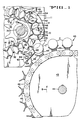
- Figure 1 is a vertical section taken through a discharge portion of a hydrostatic cooker and the input portion of an indexing conveyor illustrating the operation of the multi-drop container discharge system.
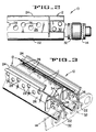
- Figure 2 is a section of a portion of one of the carriers of the indexing conveyor looking in the direction of arrows 2-2 of Figure 1.
- Figure 3 is a perspective of a portion of two carriers of the indexing conveyor, with parts cut away and other parts shown in section.
- the apparatus of the present invention comprises an endless conveyor 10 (Fig. 1) of a hydrostatic cooker 11 (only a fragment being shown) such as that disclosed in the cross-referenced Lee Patent No. 3,286,619.
- Containers C such as glass jars, are supported in carriers 12 connected to a pair of endless chains 14 only one being shown) of the endless conveyor 10.
- the conveyor 10 is trained around small diameter discharge sprockets 18 (only one being shown) secured to a shaft 20 which is driven in a clockwise direction as indicated by the arrow A.
- each carrier 12 has a wide generally U-shaped, inner portion 22 and a smaller U-shaped outer portion 24 that is connected to the inner portion 22 by a web 26 that is perforated by holes 28 to permit heating and cooling fluids to flow therethrough and control the cooking and thereafter cooling of the containers while within the hydrostatic cookers 11.
- Each carrier 12 (Figs. 2 and 3) is connected to two endless chains 14 (only one being shown) by L-shaped connectors 30 that are rigidly connected to associated links 32 of the chain 14.
- both ends of each carrier are provided with end stops 34 which are welded to arms 36 and are bolted to the associated L-shaped connectors 30 into an end portion of the web 26 of the associated carrier 12.
- An indexing conveyor 40 (Fig. 1) includes a pair of intermittently driven endless chains 42 (only one being shown) trained around sprocket 43 keyed to a shaft 44 and having a plurality of truncated V-shaped carrier 45 secured thereto.
- the indexing conveyor 40 is intermittently driven in timed relation with conveyor 10 in the direction of arrow B by means not shown.
- An important feature of the invention is the use of a pair of arcuate support plates 46 (Fig 1) only one being shown, which includes a pair of arcuate mounting slots 48 for adjustably accepting connectors 50.
- An arcuate container guide member 52 extends in excess of the full width of the carriers 12 and includes an upper stiffening member 54 and a lower discharge timing plate 56 both of which extend the full width of the carrier 12.
- the discharge timing plate 56 is supported on the lower end of the arcuate support plates 46 in position to intercept and prevent free fall of each row of containers C', in turn, out of the carriers 12 of the endless conveyor 10. As illustrated in Figure 1, the distance between the lower end of the discharge timing plate 56 and the lower portion of the container supporting carrier 12 restricts the distance the row of containers C will free fall out of the associated carriers 12.
- a back-up bar 60 includes a container contacting surface 62, a bottom wall 64 and slotted side wall 66 (only one being shown) for receiving connectors 68 which secures the back-up bar 60 in adjusted position to the side walls of the hydrostatic cooker 11.
- the positioning of the back-up bar 60 is such that the row of containers C'' released from the conveyor 10 are initially captured between the container contacting surface 62 and a side wall 45' of a carrier 45 of the indexing conveyor 40 and remains in that position until the indexing conveyor moves the V-shaped carrier wall 45' away from the back-up bar 60 and moves another carrier 45 into position to gently receive the next row of containers.
- rows of frangible containers such as glass baby food containers, are continuously conveyed through a hydrostatic cooker for sterilization and thereafter cooling of the containers C.
- the row of containers C then gravitate into the position of the row of containers C'' (Fig. 1) at which time they are momentarily captured between the container contacting surface 62 and the side wall 45' of the truncated V-shaped carrier 45.
- the conveyor 40 then indexes the container receiving carrier 45 to the right (Fig. 1) away from the container contacting surface 62 of the back-up bar 60 at which time the row of containers drop a short distance fully into the carriers 45.
- the multi-drop container discharge system of the present invention includes a mechanism for preventing frangible containers from freely falling from a carrier of a first continuously driven conveyor, into a carrier of an intermittently driven conveyor by momentarily restricting the movement out of the first conveyor and momentarily restricting the movement of the containers fully into the second carriers on the second conveyor.
Landscapes
- Engineering & Computer Science (AREA)
- Life Sciences & Earth Sciences (AREA)
- Mechanical Engineering (AREA)
- Wood Science & Technology (AREA)
- Zoology (AREA)
- Chemical & Material Sciences (AREA)
- Food Science & Technology (AREA)
- Polymers & Plastics (AREA)
- Intermediate Stations On Conveyors (AREA)
- Food Preservation Except Freezing, Refrigeration, And Drying (AREA)
- Chain Conveyers (AREA)
- Vending Machines For Individual Products (AREA)
Claims (6)
- Dispositif servant à décharger une rangée de récipients fragiles (C) d'entre des portions de serrage extérieures adjacentes (24, 24) de deux éléments transporteurs (12, 12) coopérant entre eux, montés sur un convoyeur sans fin (10) entraîné en continu, appartenant à une étuve hydrostatique (11), dans une zone de transfert, à un élément transporteur unitaire (45) appartenant à un convoyeur pas-à-pas (40) entraîné en mouvement intermittent,
caractérisé par
une plaque de synchronisation (56) solidaire de l'étuve (11) dans la zone de transfert, pour empêcher momentanément la rangée de récipients de tomber en chute libre des portions adjacentes extérieures (24, 24) des deux éléments transporteurs (12, 12) coopérant entre eux, une barre d'appui (60) solidaire de l'étuve (11), ledit appui étant espacé de ladite plaque de synchronisation (56) et possédant une surface (62) de contact des récipients qui coopère avec une première paroi (45'), placée en position adjacente, d'un élément transporteur unitaire (45) pour retenir entre elles la rangée de récipients libérée par la plaque de synchronisation (56), et pour empêcher la rangée de récipients de pénétrer entièrement dans l'élément transporteur unitaire (45) jusqu'à ce que le mouvement intermittent du convoyeur pas-à-pas (40) fasse passer la deuxième paroi de l'élément transporteur unitaire (45) au droit de ladite barre d'appui (60). - Dispositif selon la revendication 1, caractérisé par une paire de plaques supports courbes (46, 46), un élément courbe (52) de guidage des récipients qui entoure ledit convoyeur sans fin au droit de la zone de transfert, avec un élément raidisseur supérieur (54), et ladite plaque de synchronisation (56), qui est supportée par lesdites plaques supports courbes (46).
- Dispositif selon la revendication 1, caractérisé en ce que la barre d'appui (60) comprend une paroi latérale fendue (66) avec des éléments d'assemblage (68) servant à fixer la barre d'appui (60) dans une position réglée aux parois latérales de l'étuve hydrostatique (11), la barre d'appui (60) coopérant avec les premières parois (45') des éléments transporteurs (45) montés sur le convoyeur pas-à-pas (40) pour interrompre momentanément un mouvement de gravitation de chaque rangée de récipients fragiles tombant dudit convoyeur sans fin (10).
- Dispositif selon la revendication 1, caractérisé en ce que chaque élément transporteur (12) comprend des portions intérieure (22) et extérieure (24) sensiblement en forme de U qui sont reliées par une âme (26) et en ce que ladite âme (26) est perforée de trous (28) pour laisser les fluides de chauffage et de refroidissement la traverser.
- Dispositif selon la revendication 1, caractérisé en ce que les deux extrémités de chaque élément transporteur (12) sont munies de butées terminales (34).
- Dispositif selon la revendication 5, caractérisé en ce que les butées terminales (34) sont soudées à des bras (36) et sont boulonnées à des éléments d'assemblage (30) respectifs pour former une partie terminale de l'âme (26) de l'élément transporteur respectif.
Applications Claiming Priority (2)
| Application Number | Priority Date | Filing Date | Title |
|---|---|---|---|
| US595520 | 1990-10-11 | ||
| US07/595,520 US5097942A (en) | 1990-10-11 | 1990-10-11 | Multi-drop container discharge system |
Publications (2)
| Publication Number | Publication Date |
|---|---|
| EP0480444A1 EP0480444A1 (fr) | 1992-04-15 |
| EP0480444B1 true EP0480444B1 (fr) | 1994-12-14 |
Family
ID=24383562
Family Applications (1)
| Application Number | Title | Priority Date | Filing Date |
|---|---|---|---|
| EP91117359A Expired - Lifetime EP0480444B1 (fr) | 1990-10-11 | 1991-10-10 | Système de déchargement multiple de récipients |
Country Status (4)
| Country | Link |
|---|---|
| US (1) | US5097942A (fr) |
| EP (1) | EP0480444B1 (fr) |
| AT (1) | ATE115507T1 (fr) |
| DE (1) | DE69105903T2 (fr) |
Families Citing this family (6)
| Publication number | Priority date | Publication date | Assignee | Title |
|---|---|---|---|---|
| US5170878A (en) * | 1989-12-18 | 1992-12-15 | Don Evans & Associates, Inc. | Method of hydrostatic cooker discharge |
| DE19909194B4 (de) * | 1999-03-03 | 2008-08-21 | Groninger & Co. Gmbh | Einrichtung zum Verteilen von Gegenständen |
| DE19937009A1 (de) * | 1999-08-05 | 2001-02-15 | Bosch Gmbh Robert | Vorrichtung zum Fehlstellenausgleich sukzessive geförderter Gegenstände |
| US7350601B2 (en) * | 2005-01-25 | 2008-04-01 | Smith International, Inc. | Cutting elements formed from ultra hard materials having an enhanced construction |
| US7237580B2 (en) * | 2005-02-16 | 2007-07-03 | Evergreen Packaging Inc. | Container guide for a container filling apparatus |
| US8781616B2 (en) | 2011-06-27 | 2014-07-15 | The Procter & Gamble Company | Robotic unscrambler and method |
Citations (1)
| Publication number | Priority date | Publication date | Assignee | Title |
|---|---|---|---|---|
| EP0297817A1 (fr) * | 1987-07-02 | 1989-01-04 | FECO Engineered Systems, Inc. | Système de transfert pour récipient |
Family Cites Families (8)
| Publication number | Priority date | Publication date | Assignee | Title |
|---|---|---|---|---|
| US1913947A (en) * | 1930-04-12 | 1933-06-13 | Stout Mfg Company | Bottle washing machine |
| US2910211A (en) * | 1953-06-26 | 1959-10-27 | American Can Co | Feeding mechanism for fragile articles |
| US3347351A (en) * | 1964-06-03 | 1967-10-17 | Internat Machinery Corp | Hydrostatic cooker bars |
| US3543908A (en) * | 1968-04-25 | 1970-12-01 | Mather & Platt Ltd | Transfer mechanism for container sticks |
| US3670863A (en) * | 1970-03-31 | 1972-06-20 | Gen Electric | Endless conveyor system |
| US3724644A (en) * | 1971-07-13 | 1973-04-03 | Fmc Corp | Universal carrier chain for cookers |
| US3878932A (en) * | 1973-01-22 | 1975-04-22 | Fmc Corp | Container arrester for hydrostatic cooker |
| SU1465350A1 (ru) * | 1987-06-24 | 1989-03-15 | Научно-производственное объединение птицеперерабатывающей и клеежелатиновой промышленности "Комплекс" | Устройство дл формировани потока изделий |
-
1990
- 1990-10-11 US US07/595,520 patent/US5097942A/en not_active Expired - Lifetime
-
1991
- 1991-10-10 AT AT91117359T patent/ATE115507T1/de not_active IP Right Cessation
- 1991-10-10 EP EP91117359A patent/EP0480444B1/fr not_active Expired - Lifetime
- 1991-10-10 DE DE69105903T patent/DE69105903T2/de not_active Expired - Fee Related
Patent Citations (1)
| Publication number | Priority date | Publication date | Assignee | Title |
|---|---|---|---|---|
| EP0297817A1 (fr) * | 1987-07-02 | 1989-01-04 | FECO Engineered Systems, Inc. | Système de transfert pour récipient |
Also Published As
| Publication number | Publication date |
|---|---|
| US5097942A (en) | 1992-03-24 |
| DE69105903T2 (de) | 1995-05-04 |
| EP0480444A1 (fr) | 1992-04-15 |
| ATE115507T1 (de) | 1994-12-15 |
| DE69105903D1 (de) | 1995-01-26 |
Similar Documents
| Publication | Publication Date | Title |
|---|---|---|
| US5553698A (en) | Conveyor belt apparatus for bottles | |
| US3835985A (en) | Vacuum assist can unscrambler | |
| US4684117A (en) | Method and apparatus for opening printed products which have been folded off-center | |
| EP0462497B1 (fr) | Appareil pour érection de recipients | |
| DE60127501D1 (de) | Verfahren und Vorrichtung zum förderen und/oder überführen von Früchten | |
| KR19980703486A (ko) | 물체를 뒤집고 배치하는 장치 및 방법 | |
| US4294057A (en) | Case packer apparatus including velocity compensator assembly | |
| JPH06191637A (ja) | 物品移送装置 | |
| US4274532A (en) | Can handling system | |
| WO2000037353A8 (fr) | Dispositif de transport de bouteilles | |
| NL8202431A (nl) | Machine voor het verpakken van eieren. | |
| EP0480444B1 (fr) | Système de déchargement multiple de récipients | |
| KR940000008A (ko) | 계란 수집기 | |
| EP0614654B1 (fr) | Appareil d'enrobage de comprimés | |
| EP0150954B1 (fr) | Appareil pour étamer des "dips" | |
| US3700090A (en) | Conveyor and article for handling apparatus | |
| US4560058A (en) | Container handling system | |
| GB2240529A (en) | Transport device for boards having a sensitive surface, especially for wet-coated circuit boards | |
| EP0371117B1 (fr) | Appareil servant a laver dans un espace ferme des bouchons orientes | |
| US2812085A (en) | Conveying and unloading apparatus | |
| NL8300287A (nl) | Werkwijze en inrichting voor het behandelen van kwetsbare voorwerpen alsmede houder ingericht voor toepassing bij deze werkwijze. | |
| EP0120650A2 (fr) | Appareil pour transférer des articles dans les godets d'un cartonneur | |
| EP0489478A1 (fr) | Appareil pour placer des objets sur un convoyeur | |
| SU891512A1 (ru) | Устройство дл подачи предметов | |
| NZ204764A (en) | Machine for positioning band around array of containers |
Legal Events
| Date | Code | Title | Description |
|---|---|---|---|
| PUAI | Public reference made under article 153(3) epc to a published international application that has entered the european phase |
Free format text: ORIGINAL CODE: 0009012 |
|
| AK | Designated contracting states |
Kind code of ref document: A1 Designated state(s): AT BE CH DE DK ES FR GB GR IT LI LU NL SE |
|
| 17P | Request for examination filed |
Effective date: 19920708 |
|
| 17Q | First examination report despatched |
Effective date: 19930602 |
|
| GRAA | (expected) grant |
Free format text: ORIGINAL CODE: 0009210 |
|
| ITF | It: translation for a ep patent filed | ||
| AK | Designated contracting states |
Kind code of ref document: B1 Designated state(s): AT BE CH DE DK ES FR GB GR IT LI LU NL SE |
|
| PG25 | Lapsed in a contracting state [announced via postgrant information from national office to epo] |
Ref country code: LI Effective date: 19941214 Ref country code: GR Free format text: LAPSE BECAUSE OF FAILURE TO SUBMIT A TRANSLATION OF THE DESCRIPTION OR TO PAY THE FEE WITHIN THE PRESCRIBED TIME-LIMIT Effective date: 19941214 Ref country code: ES Free format text: THE PATENT HAS BEEN ANNULLED BY A DECISION OF A NATIONAL AUTHORITY Effective date: 19941214 Ref country code: DK Effective date: 19941214 Ref country code: CH Effective date: 19941214 Ref country code: BE Effective date: 19941214 Ref country code: AT Effective date: 19941214 |
|
| REF | Corresponds to: |
Ref document number: 115507 Country of ref document: AT Date of ref document: 19941215 Kind code of ref document: T |
|
| REF | Corresponds to: |
Ref document number: 69105903 Country of ref document: DE Date of ref document: 19950126 |
|
| ET | Fr: translation filed | ||
| PG25 | Lapsed in a contracting state [announced via postgrant information from national office to epo] |
Ref country code: SE Effective date: 19950314 |
|
| REG | Reference to a national code |
Ref country code: CH Ref legal event code: PL |
|
| PLBE | No opposition filed within time limit |
Free format text: ORIGINAL CODE: 0009261 |
|
| STAA | Information on the status of an ep patent application or granted ep patent |
Free format text: STATUS: NO OPPOSITION FILED WITHIN TIME LIMIT |
|
| PG25 | Lapsed in a contracting state [announced via postgrant information from national office to epo] |
Ref country code: LU Free format text: LAPSE BECAUSE OF NON-PAYMENT OF DUE FEES Effective date: 19951031 |
|
| 26N | No opposition filed | ||
| PGFP | Annual fee paid to national office [announced via postgrant information from national office to epo] |
Ref country code: GB Payment date: 19970917 Year of fee payment: 7 |
|
| PGFP | Annual fee paid to national office [announced via postgrant information from national office to epo] |
Ref country code: DE Payment date: 19971030 Year of fee payment: 7 |
|
| PG25 | Lapsed in a contracting state [announced via postgrant information from national office to epo] |
Ref country code: GB Free format text: LAPSE BECAUSE OF NON-PAYMENT OF DUE FEES Effective date: 19981010 |
|
| GBPC | Gb: european patent ceased through non-payment of renewal fee |
Effective date: 19981010 |
|
| PG25 | Lapsed in a contracting state [announced via postgrant information from national office to epo] |
Ref country code: DE Free format text: LAPSE BECAUSE OF NON-PAYMENT OF DUE FEES Effective date: 19990803 |
|
| PGFP | Annual fee paid to national office [announced via postgrant information from national office to epo] |
Ref country code: NL Payment date: 19990921 Year of fee payment: 9 |
|
| PGFP | Annual fee paid to national office [announced via postgrant information from national office to epo] |
Ref country code: FR Payment date: 19991013 Year of fee payment: 9 |
|
| PG25 | Lapsed in a contracting state [announced via postgrant information from national office to epo] |
Ref country code: NL Free format text: LAPSE BECAUSE OF NON-PAYMENT OF DUE FEES Effective date: 20010501 |
|
| PG25 | Lapsed in a contracting state [announced via postgrant information from national office to epo] |
Ref country code: FR Free format text: LAPSE BECAUSE OF NON-PAYMENT OF DUE FEES Effective date: 20010629 |
|
| NLV4 | Nl: lapsed or anulled due to non-payment of the annual fee |
Effective date: 20010501 |
|
| REG | Reference to a national code |
Ref country code: FR Ref legal event code: ST |
|
| PG25 | Lapsed in a contracting state [announced via postgrant information from national office to epo] |
Ref country code: IT Free format text: LAPSE BECAUSE OF NON-PAYMENT OF DUE FEES;WARNING: LAPSES OF ITALIAN PATENTS WITH EFFECTIVE DATE BEFORE 2007 MAY HAVE OCCURRED AT ANY TIME BEFORE 2007. THE CORRECT EFFECTIVE DATE MAY BE DIFFERENT FROM THE ONE RECORDED. Effective date: 20051010 |