EP0480463A2 - Boîtier pour cassette à bande magnétique et sa carte d'index - Google Patents
Boîtier pour cassette à bande magnétique et sa carte d'index Download PDFInfo
- Publication number
- EP0480463A2 EP0480463A2 EP91117386A EP91117386A EP0480463A2 EP 0480463 A2 EP0480463 A2 EP 0480463A2 EP 91117386 A EP91117386 A EP 91117386A EP 91117386 A EP91117386 A EP 91117386A EP 0480463 A2 EP0480463 A2 EP 0480463A2
- Authority
- EP
- European Patent Office
- Prior art keywords
- magnetic tape
- case
- tape cassette
- index sheet
- Prior art date
- Legal status (The legal status is an assumption and is not a legal conclusion. Google has not performed a legal analysis and makes no representation as to the accuracy of the status listed.)
- Granted
Links
- 238000005452 bending Methods 0.000 claims abstract description 7
- 238000000034 method Methods 0.000 claims description 4
- 230000007423 decrease Effects 0.000 claims description 3
- 238000004519 manufacturing process Methods 0.000 abstract description 7
- 239000000428 dust Substances 0.000 description 5
- 238000003780 insertion Methods 0.000 description 4
- 230000037431 insertion Effects 0.000 description 4
- 238000012986 modification Methods 0.000 description 2
- 230000004048 modification Effects 0.000 description 2
- 239000000853 adhesive Substances 0.000 description 1
- 230000001070 adhesive effect Effects 0.000 description 1
- 230000006835 compression Effects 0.000 description 1
- 238000007906 compression Methods 0.000 description 1
- 238000010276 construction Methods 0.000 description 1
- 239000011347 resin Substances 0.000 description 1
- 229920005989 resin Polymers 0.000 description 1
- 238000013022 venting Methods 0.000 description 1
Images

Classifications
-
- G—PHYSICS
- G11—INFORMATION STORAGE
- G11B—INFORMATION STORAGE BASED ON RELATIVE MOVEMENT BETWEEN RECORD CARRIER AND TRANSDUCER
- G11B23/00—Record carriers not specific to the method of recording or reproducing; Accessories, e.g. containers, specially adapted for co-operation with the recording or reproducing apparatus ; Intermediate mediums; Apparatus or processes specially adapted for their manufacture
- G11B23/02—Containers; Storing means both adapted to cooperate with the recording or reproducing means
- G11B23/023—Containers for magazines or cassettes
- G11B23/0233—Containers for a single cassette
-
- G—PHYSICS
- G11—INFORMATION STORAGE
- G11B—INFORMATION STORAGE BASED ON RELATIVE MOVEMENT BETWEEN RECORD CARRIER AND TRANSDUCER
- G11B23/00—Record carriers not specific to the method of recording or reproducing; Accessories, e.g. containers, specially adapted for co-operation with the recording or reproducing apparatus ; Intermediate mediums; Apparatus or processes specially adapted for their manufacture
- G11B23/38—Visual features other than those contained in record tracks or represented by sprocket holes the visual signals being auxiliary signals
- G11B23/40—Identifying or analogous means applied to or incorporated in the record carrier and not intended for visual display simultaneously with the playing-back of the record carrier, e.g. label, leader, photograph
Definitions
- the present invention relates generally to a magnetic tape cassette case, and more particularly to a case for receiving a magnetic tape cassette with an index card disposed therebetween, wherein the case or index card where air entrapped in the pocket-shaped portion of the case is vented when the cassette and index card are inserted therein.
- An audio or video magnetic tape cassette (hereinafter referred to simply as a cassette) when in an inoperative state is typically stored in a magnetic tape cassette case (hereinafter referred to simply as a case).
- the case is used primarily for protecting the cassette from damage due to external forces and for preventing dust from entering the interior of the cassette.
- the performance of magnetic tape cassettes and recording/reproducing apparatus have improved such that even a minute amount of dust clinging to a magnetic tape is likely to cause problems such as signal dropout. Therefore, it is very important to prevent dust from entering the cassette.
- Magnetic tape cassette cases most of which are made of plastic, include an inner housing portion having a pocket into which the cassette is inserted, and an outer housing portion pivotally coupled to the inner housing portion so that they can be closed and opened to and from each other.
- Other cases are made of a resin sheet punched out to a prescribed form, bent, and conjoined to itself with an adhesive so as to he shaped like a book container.
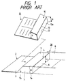
- a conventional case is provided with an index sheet 11 which allows such items to be written thereon, as shown in Fig. 1.
- Fig. 1 a conventional case is shown and will now be described in more detail.
- the case 30 includes a cover 2 having a pocket 4, and a casing portion 8 represented by phantom lines pivotally coupled to the cover 2.
- the casing portion 8 rotates about a support shaft (not shown), which is pivotally fitted into shaft holes 7a, to open and close the case.
- the index sheet 11, which fits into the pocket 4 of the cover 2 is formed by folding it along folding lines 12 and 13 at the right-hand end part thereof, forming a U-shaped sectional contour.
- the folded part 15 of the index sheet 11 is inserted into the pocket 4 of the cover 2, and then desired identification marks such as the title of the recorded contents can be written onto the surface of an upright wall 13a at the folded part 15 of the index sheet 11.
- the written marks can visually be read through a transparent rear surface wall 6 of the case 30.
- the cassette Since the open front part of the magnetic tape cassette is covered with the bent portion of the index sheet, the cassette is better protected from damage due to external forces.
- the height l1 of the folded part 15 of the index sheet 11 at the forwardmost end of the same is larger than the height L2 of the pocket 4.
- the conventional case constructed in the above-described manner has the following disadvantages. That is, the index sheet 11 receives a large resistance when it is inserted into the pocket 4 on a mass production line, resulting in an inefficient insertion operation. Particularly, when the index sheet 11 is inserted into the pocket 4 at high speed with automatic equipment, it receives a larger resistance due to the compression of air than from a frictional resistance because air is entrapped in the space between the pocket 4 and upright wall 13a of the index sheet 11 and cannot be vented to the outside. This further causes the index sheet 11 to be bent as it is inserted in the pocket 4. Thus, there arises another problem associated with the conventional case on a mass production line, namely, the inserting operation can bend the index sheet.
- the present invention provides a case for receiving a magnetic tape cassette including a pocket into which the magnetic tape cassette and an index sheet are inserted together in a predetermined direction, wherein a plurality of air holes are formed on a rear wall of the pocket.
- each of the air holes has a tapered sectional contour having an aperture diameter which gradually decreases toward the outer surface side of the case.
- the present invention also provides a second embodiment of a case for receiving a magnetic tape cassette including a pocket into which the magnetic tape cassette and an index sheet are inserted together in a predetermined direction, wherein a plurality of air holes are formed on a bent portion of the index card that is parallel with a rear surface of the pocket thereby reducing the pressure of air in the pocket, at the time of inserting the magnetic tape cassette and the index card.
- the invention provides a case for receiving a magnetic tape cassette including a pocket into which the magnetic tape cassette and an index sheet are inserted together, and means for venting air trapped between the pocket and the magnetic tape cassette and the index sheet when the magnetic tape cassette and the index sheet are inserted into the pocket.
- Fig. 1 is a perspective view of a conventional magnetic tape cassette case and a conventional index card.
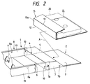
- Fig. 2 is a perspective view of a case for receiving a magnetic tape cassette in accordance with an embodiment of the present invention.
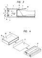
- Fig. 3 is a fragmentary sectional view of the case shown in Fig. 2.
- Fig. 4 is a perspective view of a case for receiving a magnetic tape cassette in accordance with another embodiment of the present invention, illustrating the case in a disassembled state.
- Fig. 5 is a perspective view of an index card according to another embodiment of the present invention.
- Fig. 6 is a partial sectional view of the index card of Fig. 5.
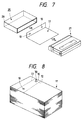
- Fig. 7 is a perspective view of an index card according to another embodiment of the present invention.
- Fig. 8 is a perspective view of the index cards shown in Fig. 5, in the state that the cards are not bent but piled together.
- Figs. 2 and 3 show a magnetic tape cassette case 1 which is essentially composed of a cover 2 including a pocket 4 in which the fore thickness increased portion of a cassette 20 is received, and a casing portion 8 including a pair of rotation-preventing projections 9 adapted to be inserted into the corresponding shaft insert holes of the cassette 20.
- the case 1 is constructed such that the casing portion 8 and the cover 2 can turnably be opened or closed by turning about a pivotal portion, which includes an opposing pair of support shafts extending inward of the casing portion 8 and shaft holes 7a formed through an opposing pair of side walls 7 of the pocket 4 so as to allow the support shafts to be fitted into the shaft holes 7a.
- the pocket 4 is arranged on the pivotal portion side of the cover 2 and has a large wall surface 3, an opposing pair of side walls 7 located on the left and right sides of the large wall surface 3, a small wall surface 5 located opposite to the large wall surface 3, and a rear or bottom surface wall 6.
- a plurality of air holes 10 are formed through the rear surface wall 6 at positions in the vicinity of the opposite ends as seen in the longitudinal direction of the rear surface wall 6. As best illustrated in Fig. 3, each of the air holes 10 is tapered such that each aperture diameter gradually decreases toward the outside surface side of the case 1.
- the small surface wall 5 of the pocket 4 positionally coincides with the bottom wall of the casing portion 8, thereby forming a common wall.
- engagement projections 7b on the side walls 7 of the pocket 4 are brought into engagement with recesses 8a on side walls 19 of the casing portion 8 to prevent the case 1 from unexpectingly opening.
- the index sheet 11 which is fitted into the pocket 4 of the cover, is folded along folding lines 12 and 13 in a U-shaped sectional contour.
- the folded part 15 of the index sheet 11 is inserted into the pocket 4 of the cover 2 so that a description, such as the title of the contents recorded on the magnetic tape cassette 20, written on the surface of an upright wall 13a of the folded part 15 can be read through the transparent rear surface wall 6 of the case 1.
- the opening portion of the magnetic tape cassette 20 is enclosed by the folded part 15 of the index sheet 11 when the two are inserted in the case 1 to further function to protect the magnetic tape cassette 20 from damage caused by external forces.
- the folded part 15 of the index sheet 11 is flexibly introduced into the interior of the pocket 4, as shown in Fig. 3.
- each air hole 10 is designed to have a tapered sectional shape such that it has a larger diameter on the pocket inner side than on the case outer side, dust is prevented from entering the interior of the pocket 4. Moreover, air is easily discharged from the interior of the pocket 4 to the outside.
- the folded part 15 of the index sheet 11 has a height substantially equal to the inner height of the pocket 4, and because it is elastically received in the pocket 4 in such a manner as to expand by its own elastic force, the index sheet 11 will not fall out of the case 11.
- the present invention should not be limited only to the aforementioned embodiment wherein the index sheet 11 is designed to have a U-shaped sectional contour. Alternatively, the present invention may equally be applied to a case where the folded part 15 of the index sheet 11 is designed to have an L-shaped sectional contour.
- a book-type case 25 which is typically used for receiving 8 mm video magnetic tape cassettes, is designed such that an index sheet 17 and a magnetic tape cassette 21 are received therein.
- the whole case 25 can be considered similar to the pocket in the preceding embodiment of the present invention.
- the folded part of the index sheet 17 is not designed in a U-shaped sectional contour but in a L-shaped sectional contour.
- air holes 10 are formed through a rear surface wall 26 of the case 25.
- a plurality of air holes are formed at the deepest positions of the pocket.
- Air holes may be formed at any positions where air can effectively be vented to the outside.
- air holes may be formed at other positions within the vicinity of the rear surface wall 6 or 26.
- the number of air holes can be determined arbitrarily.
- the contour of each air hole should not be limited only to a circle, and each air hole may be designed to have a slit-shaped contour or the like.
- a case for receiving a magnetic tape cassette is constructed such that a plurality of air holes are formed on a side wall at the deepest positions of a pocket or in the vicinity thereof, air can reliably be vented to the outside through the air holes when an index sheet is inserted into the pocket, even when the index sheet is constructed in such a manner as would otherwise entrap air in the pocket.
- air can reliably be vented to the outside through the air holes when an index sheet is inserted into the pocket, even when the index sheet is constructed in such a manner as would otherwise entrap air in the pocket.
- each case can be shipped after a cassette is received in the case together with an index sheet on an automatic mass production line in a factory, the operational efficiency for producing such cases is substantially improved.
- Figs. 5-8 show an index card 11 in accordance with another embodiment of the present invention.
- the index card 11 is bent on bending lines 12 and 13 near one end of the card so that the card is shaped as a J.
- this embodiment provides two air passage holes 10 at desired intervals in the front part 13a of the bent portion 15.
- the magnetic tape cassette 20 is pinched within the index card 11, and then pushed into the case 1 so that the bent portion 15 of the card is inserted into the pocket 4 of the inner housing portion 2 of the case while being flexed by the front portion of the cassette and the inner housing portion, as shown in Fig. 6.
- Any air in the pocket 4 is pushed toward the front part 13a of the bent portion 15 of the card 11 and vented through the air passage holes 10 of the front part.
- the air is not confined to the pocket 4, and hence is not compressed, even if the cassette 20 and the card 11 are rapidly pushed into the case 1. For this reason, the card 11 can be rapidly and efficiently inserted into the pocket 4.
- the air passage holes 10 of the card are closed by the front part 6 of inner housing portion 2 of the case 1. Since the width of the bent portion 15 of the card 11 is nearly equal to the depth of the pocket 4, and the bent portion has an elastic self-spreading force in the pocket, the card is unlikely to drop out of the pocket.
- the index card 11 may also be shaped as a different form such as an L, as shown in Fig. 7, which illustrates another embodiment of the invention.
- the L-shaped index card is for a magnetic tape cassette 21, such as an 8 mm video magnetic tape, which is housed in a case 25 shaped as a book container to constitute a pocket as a whole.
- the index card 17 is bent as an L in which the front part of the card 17 has air passage holes 10.
- the index cards 11 and 17 have not only the above-mentioned advantage, but also the further advantage for manufacturing in which the index cards are automatically inserted into the case.
- the index cards need to be prepared in a "trued-up" state on a manufacturing machine. Since the index cards have the air passage holes 10, a guide member 30 can be inserted into the holes, as shown in Fig. 8, to position the cards so that the reloading, orientation, etc. of the index cards can be easily performed.
- the present invention is not limited thereto, and the holes may be provided elsewhere so long as the air in the pocket of the case is effectively discharged or vented from the pocket at the time of inserting the card in the case.
- the holes 10 may be provided on the bending lines 13 as shown by dotted lines in Fig. 5, or provided on the other bending line 12. Since the air having gone out of the pocket 4 through the holes 10 provided on the bending line is effectively discharged through between the index card 11 and the cassette 20, the air is unlikely to enter the open front part of the cassette.
- Each of the holes 10 may be shaped not only as a circle but also as other various forms such as a slender oblong.
- the bent portion of an index card provided in accordance with the present device has air passage holes which are located at the innermost part of a pocket into which the card is inserted, air in the pocket goes out of it through the holes at the time of the insertion although the air is pushed in the pocket. For this reason, the air is prevented from being confined in the pocket at the time of the insertion.
- the fitting property of the card is thus enhanced.
- the air passage holes can be used to position the index cards in a stacked position. For this reason, the handling property of the cards is enhanced. Because of these advantages, the card and a magnetic tape cassette can be smoothly and efficiently inserted into a case through automatic operation before shipment.
- the present invention should not be limited only to the aforementioned embodiment, and may be applied to a case for receiving a VHS-system video magnetic tape cassette or a ⁇ -system video magnetic tape cassette.
Landscapes
- Packaging Of Annular Or Rod-Shaped Articles, Wearing Apparel, Cassettes, Or The Like (AREA)
Applications Claiming Priority (4)
| Application Number | Priority Date | Filing Date | Title |
|---|---|---|---|
| JP1990107387U JPH0748553Y2 (ja) | 1990-10-12 | 1990-10-12 | 磁気テープカセット収納用ケース |
| JP107387/90U | 1990-10-12 | ||
| JP3375/91U | 1991-01-11 | ||
| JP1991003375U JP2570453Y2 (ja) | 1991-01-11 | 1991-01-11 | インデックスカード |
Publications (3)
| Publication Number | Publication Date |
|---|---|
| EP0480463A2 true EP0480463A2 (fr) | 1992-04-15 |
| EP0480463A3 EP0480463A3 (en) | 1993-01-20 |
| EP0480463B1 EP0480463B1 (fr) | 1996-07-17 |
Family
ID=26336944
Family Applications (1)
| Application Number | Title | Priority Date | Filing Date |
|---|---|---|---|
| EP91117386A Expired - Lifetime EP0480463B1 (fr) | 1990-10-12 | 1991-10-11 | Boîtier pour cassette à bande magnétique et sa carte d'index |
Country Status (3)
| Country | Link |
|---|---|
| US (1) | US5135110A (fr) |
| EP (1) | EP0480463B1 (fr) |
| DE (1) | DE69120889T2 (fr) |
Cited By (1)
| Publication number | Priority date | Publication date | Assignee | Title |
|---|---|---|---|---|
| EP0676760A3 (fr) * | 1994-04-04 | 1996-03-20 | Fuji Photo Film Co Ltd | Carte d'index. |
Families Citing this family (4)
| Publication number | Priority date | Publication date | Assignee | Title |
|---|---|---|---|---|
| JP3278343B2 (ja) * | 1996-02-23 | 2002-04-30 | 富士写真フイルム株式会社 | ディスクカートリッジ収納ケース |
| US6672456B2 (en) * | 2001-06-14 | 2004-01-06 | Hewlett-Packard Delevopment Company, Lp. | Flexible packaging film pouch with internal stiffener to create an anti-pilfering package |
| US7131224B1 (en) * | 2003-07-30 | 2006-11-07 | Excelligence Learning Corporation | Storage bin with attachable label holder |
| US8074390B2 (en) * | 2009-07-06 | 2011-12-13 | Michele Trevison Rain | Display box |
Family Cites Families (5)
| Publication number | Priority date | Publication date | Assignee | Title |
|---|---|---|---|---|
| US4297826A (en) * | 1979-08-23 | 1981-11-03 | Helmuth Woertche | Apparatus for packaging tape cassettes |
| US4385693A (en) * | 1981-02-27 | 1983-05-31 | Gelardi Anthony L | Origin identity insert for packaged cassettes |
| US4520927A (en) * | 1982-01-30 | 1985-06-04 | Dai Nippon Insatsu Kabushiki Kaisha | Heat-sealable package blank for a video tape cassette |
| US4987999A (en) * | 1990-01-22 | 1991-01-29 | Alpha Enterprises, Inc. | Videocassette storage and display sleeve |
| JP2791715B2 (ja) * | 1990-02-13 | 1998-08-27 | 富士写真フイルム株式会社 | カセット収納方法及びインデックスカード |
-
1991
- 1991-10-11 US US07/774,889 patent/US5135110A/en not_active Expired - Lifetime
- 1991-10-11 EP EP91117386A patent/EP0480463B1/fr not_active Expired - Lifetime
- 1991-10-11 DE DE69120889T patent/DE69120889T2/de not_active Expired - Fee Related
Cited By (1)
| Publication number | Priority date | Publication date | Assignee | Title |
|---|---|---|---|---|
| EP0676760A3 (fr) * | 1994-04-04 | 1996-03-20 | Fuji Photo Film Co Ltd | Carte d'index. |
Also Published As
| Publication number | Publication date |
|---|---|
| DE69120889T2 (de) | 1996-11-28 |
| EP0480463B1 (fr) | 1996-07-17 |
| EP0480463A3 (en) | 1993-01-20 |
| US5135110A (en) | 1992-08-04 |
| DE69120889D1 (de) | 1996-08-22 |
Similar Documents
| Publication | Publication Date | Title |
|---|---|---|
| US5475674A (en) | Disc case for removably housing data discs | |
| EP1197444A1 (fr) | Boitier de rangement de cassettes | |
| US4497009A (en) | Magnetic disk cartridge | |
| US5135110A (en) | Magnetic tape cassette case and index card therefor | |
| US5515358A (en) | Disk cartridge and method for constructing the same | |
| JPS6043282A (ja) | カセツト | |
| US6023398A (en) | Disk cartridge with rotatable cartridge door | |
| US6112901A (en) | Holding case capable of holding IC card certainly | |
| EP0391465A1 (fr) | Dispositif présentant une ouverture d'entrée de dimension standard | |
| EP0446629B1 (fr) | Méthode de rangement d'une cassette et carte à index pour boîte à cassette | |
| US4809113A (en) | Tape cassette with improved cover structure | |
| JPH06191584A (ja) | 収納ケース | |
| US5560482A (en) | Magnetic tape cassette-accommodating case having an easily deformable index card | |
| JP2550294B2 (ja) | データキャリア用のホルダー | |
| US5761015A (en) | Magnetic disk cartridge having a shutter member provided with a slit at a corner portion | |
| EP0537678B1 (fr) | Boîtier d'emmagasinage de cassette à bande magnétique | |
| JP2570453Y2 (ja) | インデックスカード | |
| JPH0748553Y2 (ja) | 磁気テープカセット収納用ケース | |
| US5381893A (en) | Housing case for tape cassette with index card | |
| EP1061519B1 (fr) | Cassette à bande | |
| JPH0620913B2 (ja) | 記録担体用の直方体状の枢転可能なケース | |
| JPS6160479A (ja) | カセツトケ−ス | |
| US6388837B1 (en) | Tape cartridge | |
| KR200325361Y1 (ko) | 다저장매체를 위한 2-in-1 커넥터구조 | |
| JP2632546B2 (ja) | 磁気テープカートリッジ |
Legal Events
| Date | Code | Title | Description |
|---|---|---|---|
| PUAI | Public reference made under article 153(3) epc to a published international application that has entered the european phase |
Free format text: ORIGINAL CODE: 0009012 |
|
| AK | Designated contracting states |
Kind code of ref document: A2 Designated state(s): DE NL |
|
| PUAL | Search report despatched |
Free format text: ORIGINAL CODE: 0009013 |
|
| AK | Designated contracting states |
Kind code of ref document: A3 Designated state(s): DE NL |
|
| 17P | Request for examination filed |
Effective date: 19930414 |
|
| 17Q | First examination report despatched |
Effective date: 19950302 |
|
| GRAH | Despatch of communication of intention to grant a patent |
Free format text: ORIGINAL CODE: EPIDOS IGRA |
|
| GRAH | Despatch of communication of intention to grant a patent |
Free format text: ORIGINAL CODE: EPIDOS IGRA |
|
| GRAA | (expected) grant |
Free format text: ORIGINAL CODE: 0009210 |
|
| AK | Designated contracting states |
Kind code of ref document: B1 Designated state(s): DE NL |
|
| PG25 | Lapsed in a contracting state [announced via postgrant information from national office to epo] |
Ref country code: NL Free format text: LAPSE BECAUSE OF FAILURE TO SUBMIT A TRANSLATION OF THE DESCRIPTION OR TO PAY THE FEE WITHIN THE PRESCRIBED TIME-LIMIT Effective date: 19960717 |
|
| REF | Corresponds to: |
Ref document number: 69120889 Country of ref document: DE Date of ref document: 19960822 |
|
| NLV1 | Nl: lapsed or annulled due to failure to fulfill the requirements of art. 29p and 29m of the patents act | ||
| PLBE | No opposition filed within time limit |
Free format text: ORIGINAL CODE: 0009261 |
|
| STAA | Information on the status of an ep patent application or granted ep patent |
Free format text: STATUS: NO OPPOSITION FILED WITHIN TIME LIMIT |
|
| 26N | No opposition filed | ||
| PGFP | Annual fee paid to national office [announced via postgrant information from national office to epo] |
Ref country code: DE Payment date: 20081014 Year of fee payment: 18 |
|
| PG25 | Lapsed in a contracting state [announced via postgrant information from national office to epo] |
Ref country code: DE Free format text: LAPSE BECAUSE OF NON-PAYMENT OF DUE FEES Effective date: 20100501 |