EP0480604A1 - Dispositif d'aspiration - Google Patents
Dispositif d'aspiration Download PDFInfo
- Publication number
- EP0480604A1 EP0480604A1 EP91308858A EP91308858A EP0480604A1 EP 0480604 A1 EP0480604 A1 EP 0480604A1 EP 91308858 A EP91308858 A EP 91308858A EP 91308858 A EP91308858 A EP 91308858A EP 0480604 A1 EP0480604 A1 EP 0480604A1
- Authority
- EP
- European Patent Office
- Prior art keywords
- suction
- passage
- outlet
- opening
- fluid
- Prior art date
- Legal status (The legal status is an assumption and is not a legal conclusion. Google has not performed a legal analysis and makes no representation as to the accuracy of the status listed.)
- Withdrawn
Links
Images
Classifications
-
- B—PERFORMING OPERATIONS; TRANSPORTING
- B23—MACHINE TOOLS; METAL-WORKING NOT OTHERWISE PROVIDED FOR
- B23Q—DETAILS, COMPONENTS, OR ACCESSORIES FOR MACHINE TOOLS, e.g. ARRANGEMENTS FOR COPYING OR CONTROLLING; MACHINE TOOLS IN GENERAL CHARACTERISED BY THE CONSTRUCTION OF PARTICULAR DETAILS OR COMPONENTS; COMBINATIONS OR ASSOCIATIONS OF METAL-WORKING MACHINES, NOT DIRECTED TO A PARTICULAR RESULT
- B23Q11/00—Accessories fitted to machine tools for keeping tools or parts of the machine in good working condition or for cooling work; Safety devices specially combined with or arranged in, or specially adapted for use in connection with, machine tools
- B23Q11/0042—Devices for removing chips
- B23Q11/006—Devices for removing chips by sucking and blowing simultaneously
-
- A—HUMAN NECESSITIES
- A61—MEDICAL OR VETERINARY SCIENCE; HYGIENE
- A61C—DENTISTRY; APPARATUS OR METHODS FOR ORAL OR DENTAL HYGIENE
- A61C17/00—Devices for cleaning, polishing, rinsing or drying teeth, teeth cavities or prostheses; Saliva removers; Dental appliances for receiving spittle
Definitions
- This invention relates to suction devices.
- the invention seeks to provide a suction device which provides a convenient means for removing or disposing of swarf, dust, fluff or other waste material, which is reliable in operation and inexpensive to make, and which can be used to blow material away in traditional manner, if so desired.
- a suction device having a suction opening, a fluid inlet for connection to a source of fluid under pressure, a fluid outlet, a suction passage between the suction opening and the outlet, a restricted passage connecting the inlet to the suction passage intermediate the suction opening and the outlet and arranged so that in use fluid flowing from the restricted passage is directed towards the outlet to create a depression in the suction passage to provide suction at the suction opening, and selection means for closing-off or substantially closing-off the suction passage from the outlet so as in use to create a jet of fluid through the suction opening as an alternative to providing suction at the suction opening.
- the restricted passage surrounds the suction passage and, in this case, the restricted passage may have a first part extending co-axially with the suction passage and a second part which converges on the suction passage in a direction away from the suction opening.
- the device includes a body and the selection means comprises a control element angularly movable in the body to connect and disconnect (or substantially disconnect) the suction passage and the outlet.
- the restricted passage may be defined by the body and the control element and the control element may be shaped such that angular movement of the control element does not affect the restricted passage.
- a bleed passage is provided between the suction passage and the outlet when the selection means is in its substantially closed-off position.
- the suction device may also comprise a valve for controlling the flow of fluid between the inlet ad the suction passage.
- the device has a gun-shaped body having a barrel section and a handle, the suction passage being formed in the barrel section and the outlet being provided in the handle.
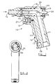
- the suction device shown therein is generally indicated at 10 and comprises a gun-shaped body 11, a valve 12 and a control element 13 which is rotatably mounted in the body 11.
- the body 11 defines a suction opening or nozzle 14 which opens into a chamber 15 for receiving the control element 13.
- the body 11 and control element 13 together define a compressed air path 16 which comprises an air inlet 17, control valve 12, a restricted passage 19, a suction passage 20 and an outlet 21.
- the restricted passage 19 is formed by an annular cut-out on the outer surface of the generally cylindrical control element 13 and debouches into the suction passage 20 by means of a rearwardly facing inclined annular outlet 22.
- the control element is further formed with a bleed passage 23 which extends at right angles to the downstream end of the suction passage 20.
- the control element is sealed with the body be means of 0-rings 24 and is held in the body by a screw-threaded retaining device 25.
- FIG. 1 the device is shown in a suction mode and operates in the following manner.
- a knob 27 of the control valve 12 When a knob 27 of the control valve 12 is depressed compressed air flows from a source (not shown) through the air inlet 17 into the restricted passage 19.
- the air speed in the passage 19 is very considerably increased with the result that the passage of the fast moving air into the broad suction passage 20 creates a depression within the suction passage 20 and hence a suction at the opening 14.
- the operator can suck up swarf, dust, fluff or other waste material, by passing the suction opening 14 over the surface to be cleaned and depressing the valve knob 27. Material drawn into the opening by the depression in the suction passage 20 gets caught in the fluid stream and passes rapidly out of the outlet 21.
- the outlet 21 can be connected to a variety of reservoirs which will filter the waste from the airstream. Indeed the connection between the outlet 21 and the reservoir (not shown) may itself be porous to enhance the filtering effect.
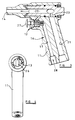
- the control element 13 is rotated, by means of its handle 26, through 90° so that it is in the position shown in Figures 3 and 4.
- the suction passage 20 is substantially closed off from the outlet 21 with the result that the air strikes the closed end of the suction passage and is deflected through the opening 14.
- the suction passage 20 is still connected to the outlet 21 by means of the bleed passage 23 so that in the event of the opening 14 becoming blocked the air will pass out through the outlet.
- the opening or nozzle 14 may be internally or externally threaded to receive either jet defining devices or suction tools. For example, if it is desired to clean out a machine bore or a sump tank a flexible tube can be connected to the opening 14 with the result that the suction can be located at points far out of the operator's reach.
- the device can be turned into a handling or lifting device by attaching a suction cup to surround the opening. This would be particularly useful for lifting sheet metal on to a machine for machining and can form a lifting device for a robot arm. If the device is to be operated automatically, then the valve 12 can be dispensed with and the device merely controlled by pulsed compressed air.
- water or other fluid could be readily used to create the suction instead of compressed air and this may be particularly useful where water cleaning of dirty tanks, such as oil tanks, takes place, as the tank can be initially hosed down using the "blow mode" and the dirty water can then be sucked up in the suction mode.
Landscapes
- Health & Medical Sciences (AREA)
- Dentistry (AREA)
- Epidemiology (AREA)
- Life Sciences & Earth Sciences (AREA)
- Animal Behavior & Ethology (AREA)
- General Health & Medical Sciences (AREA)
- Public Health (AREA)
- Veterinary Medicine (AREA)
- Engineering & Computer Science (AREA)
- Mechanical Engineering (AREA)
- Cleaning In General (AREA)
Applications Claiming Priority (2)
| Application Number | Priority Date | Filing Date | Title |
|---|---|---|---|
| GB909021774A GB9021774D0 (en) | 1990-10-06 | 1990-10-06 | Suction devices |
| GB9021774 | 1990-10-06 |
Publications (1)
| Publication Number | Publication Date |
|---|---|
| EP0480604A1 true EP0480604A1 (fr) | 1992-04-15 |
Family
ID=10683348
Family Applications (1)
| Application Number | Title | Priority Date | Filing Date |
|---|---|---|---|
| EP91308858A Withdrawn EP0480604A1 (fr) | 1990-10-06 | 1991-09-27 | Dispositif d'aspiration |
Country Status (2)
| Country | Link |
|---|---|
| EP (1) | EP0480604A1 (fr) |
| GB (2) | GB9021774D0 (fr) |
Cited By (1)
| Publication number | Priority date | Publication date | Assignee | Title |
|---|---|---|---|---|
| DE19709376A1 (de) * | 1997-03-07 | 1998-09-10 | Focke & Co | Vorrichtung zum Absaugen oder Wegblasen von festen oder flüssigen Substanzen |
Families Citing this family (14)
| Publication number | Priority date | Publication date | Assignee | Title |
|---|---|---|---|---|
| USD1054131S1 (en) * | 2022-09-16 | 2024-12-10 | Lg Electronics Inc. | Vacuum cleaner body |
| USD1047321S1 (en) * | 2022-09-30 | 2024-10-15 | Guangdong Well Technology Co., Ltd | Hand-held vacuum cleaner |
| USD1041102S1 (en) * | 2023-08-22 | 2024-09-03 | Ningbo Shanen Electric Appliance Co., Ltd. | Vacuum cleaner |
| USD1051528S1 (en) * | 2023-10-16 | 2024-11-12 | Xiao Zhu | Car vacuum cleaner |
| USD1075197S1 (en) * | 2023-10-31 | 2025-05-13 | Shenzhen Fanttik Technology Innovation Co., Ltd. | Electric air duster |
| USD1084569S1 (en) * | 2024-01-03 | 2025-07-15 | Wei Li | Portable handheld vacuum cleaner |
| USD1088377S1 (en) * | 2024-01-11 | 2025-08-12 | Jiquan Ding | Car vacuum cleaner |
| USD1105663S1 (en) * | 2024-02-29 | 2025-12-09 | Jiquan Ding | Vacuum cleaner |
| USD1100391S1 (en) * | 2024-02-29 | 2025-10-28 | Shujia Shan | Portable vacuum cleaner |
| USD1101323S1 (en) * | 2024-06-27 | 2025-11-04 | ShenZhen MaiZhan Technology Co., Ltd | Vacuum cleaner |
| USD1123273S1 (en) * | 2024-09-29 | 2026-04-21 | Jiangsu Prestin Smart Home Co., Ltd. | Vacuum cleaner |
| USD1076294S1 (en) * | 2024-12-10 | 2025-05-20 | Dongguan Super Electric Technology Co., Ltd | Car vacuum cleaner |
| USD1082188S1 (en) * | 2025-01-02 | 2025-07-01 | Bin Hu | Car vacuum cleaner |
| USD1098639S1 (en) * | 2025-03-06 | 2025-10-14 | Taiyuan Jietong Cross-border E-commerce | Multifunctional vacuum cleaner |
Citations (4)
| Publication number | Priority date | Publication date | Assignee | Title |
|---|---|---|---|---|
| DE908331C (de) * | 1944-01-01 | 1954-04-05 | Siemens Ag | Spanblaeser fuer Bohrloecher |
| JPS5856749A (ja) * | 1981-09-25 | 1983-04-04 | Yamazaki Mazak Corp | 切屑吸取機能を付属した工作機械 |
| EP0126793A1 (fr) * | 1983-05-28 | 1984-12-05 | TBT Tiefbohrtechnik GmbH und Co. KG. | Dispositif d'aspiration d'un agent de refroidissement et/ou de graissage hors d'un trou sur une machine à percer des trous profonds |
| JPS62228349A (ja) * | 1986-03-27 | 1987-10-07 | Seibu Electric & Mach Co Ltd | Nc旋盤におけるワ−クのアンロ−ド方法 |
Family Cites Families (1)
| Publication number | Priority date | Publication date | Assignee | Title |
|---|---|---|---|---|
| GB2147197A (en) * | 1983-09-29 | 1985-05-09 | Clarke Douglas C | Suction devices |
-
1990
- 1990-10-06 GB GB909021774A patent/GB9021774D0/en active Pending
-
1991
- 1991-09-27 EP EP91308858A patent/EP0480604A1/fr not_active Withdrawn
- 1991-09-27 GB GB9120531A patent/GB2248383A/en not_active Withdrawn
Patent Citations (4)
| Publication number | Priority date | Publication date | Assignee | Title |
|---|---|---|---|---|
| DE908331C (de) * | 1944-01-01 | 1954-04-05 | Siemens Ag | Spanblaeser fuer Bohrloecher |
| JPS5856749A (ja) * | 1981-09-25 | 1983-04-04 | Yamazaki Mazak Corp | 切屑吸取機能を付属した工作機械 |
| EP0126793A1 (fr) * | 1983-05-28 | 1984-12-05 | TBT Tiefbohrtechnik GmbH und Co. KG. | Dispositif d'aspiration d'un agent de refroidissement et/ou de graissage hors d'un trou sur une machine à percer des trous profonds |
| JPS62228349A (ja) * | 1986-03-27 | 1987-10-07 | Seibu Electric & Mach Co Ltd | Nc旋盤におけるワ−クのアンロ−ド方法 |
Cited By (1)
| Publication number | Priority date | Publication date | Assignee | Title |
|---|---|---|---|---|
| DE19709376A1 (de) * | 1997-03-07 | 1998-09-10 | Focke & Co | Vorrichtung zum Absaugen oder Wegblasen von festen oder flüssigen Substanzen |
Also Published As
| Publication number | Publication date |
|---|---|
| GB9021774D0 (en) | 1990-11-21 |
| GB9120531D0 (en) | 1991-11-06 |
| GB2248383A (en) | 1992-04-08 |
Similar Documents
| Publication | Publication Date | Title |
|---|---|---|
| EP0480604A1 (fr) | Dispositif d'aspiration | |
| US7455486B2 (en) | Dust extracting device | |
| EP3299120B1 (fr) | Extracteur de fumée | |
| JP3207201B2 (ja) | 二重サイクロン式真空掃除機 | |
| US3897604A (en) | Apparatus and process for removing chips from blind holes | |
| US4827955A (en) | Device for cleaning paint distributing channels in spray guns | |
| GB2035787A (en) | Suction cleaning device | |
| KR200239294Y1 (ko) | 다기능용 에어건. | |
| US4314671A (en) | Pressure jet spray apparatus | |
| US5613272A (en) | Accessory crevice tool for use with water extraction cleaning machine | |
| US5494501A (en) | Lubricant separator for a pneumatic tool lubrication system | |
| EP0280831A1 (fr) | Appareil de filtration, en particulier pour un aspirateur | |
| US5427203A (en) | Pneumatic tool lubrication system | |
| US5924166A (en) | Cleaning gun adjustable to blowing and suction functions | |
| US5107632A (en) | Device for separating blasting dust from blasting agent | |
| JPH09174010A (ja) | ドレン通し装置 | |
| GB2147197A (en) | Suction devices | |
| GB2270463A (en) | Suction apparatus for cleaning or other purposes | |
| JP3965365B2 (ja) | はんだ鏝用鏝先浄化装置 | |
| US6146137A (en) | Contamination prevention device for ultra high speed dental type handpieces | |
| US20060060670A1 (en) | Spray device | |
| EP1676648B1 (fr) | Appareil à jet d'eau et procédé correspondant | |
| EP1920698A1 (fr) | Aspirateur industriel pour liquides et solides | |
| US11540683B2 (en) | Portable glue vacuum reservoir and vacuum tool with capture reservoir | |
| KR19990008099U (ko) | 흡입 및 불기 기능을 구비한 에어건 |
Legal Events
| Date | Code | Title | Description |
|---|---|---|---|
| PUAI | Public reference made under article 153(3) epc to a published international application that has entered the european phase |
Free format text: ORIGINAL CODE: 0009012 |
|
| AK | Designated contracting states |
Kind code of ref document: A1 Designated state(s): CH DE ES FR IT LI SE |
|
| STAA | Information on the status of an ep patent application or granted ep patent |
Free format text: STATUS: THE APPLICATION IS DEEMED TO BE WITHDRAWN |
|
| 18D | Application deemed to be withdrawn |
Effective date: 19921016 |