EP0480609A1 - Injecteur de combustible pour moteur à combustion interne - Google Patents
Injecteur de combustible pour moteur à combustion interne Download PDFInfo
- Publication number
- EP0480609A1 EP0480609A1 EP91308926A EP91308926A EP0480609A1 EP 0480609 A1 EP0480609 A1 EP 0480609A1 EP 91308926 A EP91308926 A EP 91308926A EP 91308926 A EP91308926 A EP 91308926A EP 0480609 A1 EP0480609 A1 EP 0480609A1
- Authority
- EP
- European Patent Office
- Prior art keywords
- segment
- fuel
- injector
- reed
- fuel injector
- Prior art date
- Legal status (The legal status is an assumption and is not a legal conclusion. Google has not performed a legal analysis and makes no representation as to the accuracy of the status listed.)
- Withdrawn
Links
Images

Classifications
-
- F—MECHANICAL ENGINEERING; LIGHTING; HEATING; WEAPONS; BLASTING
- F02—COMBUSTION ENGINES; HOT-GAS OR COMBUSTION-PRODUCT ENGINE PLANTS
- F02M—SUPPLYING COMBUSTION ENGINES IN GENERAL WITH COMBUSTIBLE MIXTURES OR CONSTITUENTS THEREOF
- F02M51/00—Fuel-injection apparatus characterised by being operated electrically
- F02M51/06—Injectors peculiar thereto with means directly operating the valve needle
- F02M51/061—Injectors peculiar thereto with means directly operating the valve needle using electromagnetic operating means
- F02M51/0625—Injectors peculiar thereto with means directly operating the valve needle using electromagnetic operating means characterised by arrangement of mobile armatures
-
- F—MECHANICAL ENGINEERING; LIGHTING; HEATING; WEAPONS; BLASTING
- F02—COMBUSTION ENGINES; HOT-GAS OR COMBUSTION-PRODUCT ENGINE PLANTS
- F02M—SUPPLYING COMBUSTION ENGINES IN GENERAL WITH COMBUSTIBLE MIXTURES OR CONSTITUENTS THEREOF
- F02M51/00—Fuel-injection apparatus characterised by being operated electrically
- F02M51/06—Injectors peculiar thereto with means directly operating the valve needle
- F02M51/061—Injectors peculiar thereto with means directly operating the valve needle using electromagnetic operating means
- F02M51/0625—Injectors peculiar thereto with means directly operating the valve needle using electromagnetic operating means characterised by arrangement of mobile armatures
- F02M51/0635—Injectors peculiar thereto with means directly operating the valve needle using electromagnetic operating means characterised by arrangement of mobile armatures having a plate-shaped or undulated armature not entering the winding
- F02M51/0639—Injectors peculiar thereto with means directly operating the valve needle using electromagnetic operating means characterised by arrangement of mobile armatures having a plate-shaped or undulated armature not entering the winding the armature acting as a valve
Definitions
- the present invention relates to an injector for providing fuel to one or more cylinders of an internal combustion engine.
- Electromagnetically driven fuel injectors have been widely used in automotive internal combustion engines for many years. Such injectors typically rely upon an axially extending needle valve which is slidably mounted within the injector and which reciprocates each time the injector fires so as to meter the desired amount of fuel into the engine's cylinder or intake manifold. Conventional injectors can be quite noisy during operation. A more worrisome aspect of the conventional injector arises from the fact that alcohol blend fuels finding increasing acceptance in the market-place are likely to attack such sliding surfaces, leaving behind corrosion which could impair the operation of the injector.
- an injector made according to this invention will not rely upon the sliding action of a needle to meter the desired amount of fuel and, as a result, such injector will be better able to withstand the effects of corrosion resulting from hostile fuels.
- U.S. 2,881,980 to Beck et al. and U.S. 4,515,129 to Stettner disclose electromagnetically driven automotive fuel injectors in which the metering elements comprise relatively massive discs which must be reciprocated electromagnetically in order to meter the desired amount of fuel. Each of these injectors would be expected to suffer from inferior time response characteristics arising from the magnitude of the reciprocating masses.
- U.S. 3,961,644 to Eckert and U.S. 4,763,635 to Ballhause et al. each disclose electromagnetically driven valves for use in automotive fuel systems.
- the '644 patent discloses a valve having a circular membrane clamped about its periphery and having a centre section which contacts a valve seat.
- the valve disclosed in the '635 patent is intended to control the flow of vapours from an evaporative emission control system into the intake of an engine and includes a leaf spring with an attached armature, with the armature coming into sealing contact with the valve seat.
- Neither of these valves includes a flow control element having the degree of freedom and, hence, the time response characteristics, of an injector according to the present invention.
- U.S. 3,751,001 to Rayment and U.S. 4,418,886 to Holzer disclose other types of electromagnetically operated valves which are not suitable for the high speed operation required of an internal combustion engine fuel injector.
- the '001 patent discloses a valve having a rotating disc which is moved into and out of sealing contact with a slot formed in one end of the valve housing.
- the '886 patent discloses a pilot valve operated device. Neither of these designs is practical for use in an engine fuel injector.
- a fuel injector for an internal combustion engine comprising,
- the fuel injector embodying the invention has an advantage that it has reduced operating noise as compared to conventional needle type injectors, and has superior sealing characteristics to prevent after-injection, which may cause undesirable increases in engine exhaust emissions. Further the fuel injector has improved response time, and is highly resistant to the corrosive effects of alcohol blended fuels.
- a fuel injector, 10, for an internal combustion engine has a housing which is adapted for receiving liquid fuel therein and which has a terminal provision for connecting the injector to an engine control computer.
- inlet port 12 at the top of the injector is equipped with filter 13 and provides a connector for attaching a fuel rail to the injector for supplying the injector with liquid fuel.
- Fuel entering the injector at inlet port 12 moves downwardly through closing spring adjuster 22, which has bore 32 contained therein. Bore 32 is coaxial with the axial centerline of the injector.
- Closing spring adjuster 22 is contained within inlet section 20 of the injector. Fuel moving through bore 32 eventually passes radially outward through fuel outflow ports 30 formed within the lower part of inlet section 20.
- fuel then flows past reed 46, which comprises a segment of generally planar valve body 42, and then out through orifice 52 which is formed in orifice plate 54.
- reed 46 which comprises a segment of generally planar valve body 42
- orifice 52 which is formed in orifice plate 54.
- orifice plate 54 could have not only the single orifice shown at 52 in Figure 3, but also a plurality of orifices according to the demands of the engine being supplied with fuel by an injector according to the present invention.
- an injector according to this invention allows an interconnection with high speed engines operated by digital electronic microprocessor computers.
- terminal 14 located at the outside of housing 10, connected by means of lead 18 to solenoid coil 16, allows an interconnection with an engine control computer (not shown).
- Solenoid coil 16 is wound about plastic bobbin 26.
- flux guide 36 which is positioned at the bottom of the injector immediately above planar valve body 42.
- the magnetic flux then impinges upon armature 40 and drives reed 46 to an open position against the force of closing spring 24.
- closing spring 24 is positioned between closing spring adjuster 22 and the uppermost surface of armature 40.
- the injector depicted in the Figures is normally closed because spring 24 will maintain reed 46 in a closed position against orifice plate 54 unless and until the voltage is applied to terminal 14 to excite coil 16.
- reed 46 and armature 40 have relatively less mass than do the needle and armature of conventional injectors, the time response characteristics of the present injector are expected to be very favourable.
- Closing spring adjuster 22 is employed for the purpose of compressing closing spring 24 to produce a predetermined static clamp load upon armature 40. This load is set during assembly of the injector by first assembling the bulk of the injector's components and by then pressing the closing spring adjuster axially downward until the desired flow rate is obtained, followed by crimping inlet section 20 about the outer diameter of the closing spring adjuster.
- the design of the valve elements in this injector will allow operation without closing spring 24 because the spring force developed by reed 46 and the hydraulic force developed by the pressure of fuel acting upon the reed will be sufficient to close the injector.
- inclusion of a closing spring is optional with the present injector.
- Figure 3 shows the normally open position of reed 46. Note that the reed is in the maximum open position, in which the top of the reed is in contact with the lower surface of flux guide 36.
- Figure 3 further shows seat 55, which is formed integrally with orifice plate 54. Those skilled in the art will appreciate in view of this disclosure that other types of seat configurations could be employed for sealing reed 46 to orifice plate 54.
- Figures 3 and 4 show one manner in which the stroke of an injector according to the present invention may be set.
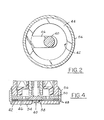
- reed 46 is cantilevered from annular land 44 of planar valve body 42, with the reed extending inwardly past the axial centerline of the injector. Because reed 46 is attached to, and indeed, integral with, planar valve body 42 only at one end of the reed, reed 46 has considerable freedom to move up and down, and to thereby move into and out of sealing contact with orifice plate 54.
- reed 46 could be attached to, and integral with, other types of base structures in addition to the annular structure illustrated in Figure 2.
- stroke spacers 48 The extent to which reed 46 can move up and down and thereby, the total extent of its stroke, is determined by stroke spacers 48, which are shown with particularity in Figures 3 and 4.
- a first stroke spacer 48 is superimposed upon orifice plate 54.
- Planar valve body 42 follows next, with a second stroke spacer 48 being superimposed upon the planar valve body.
- the total installed height of the two stroke spacers 48 minus the height of seat 55, determines the maximum stroke to which reed 46 can be lifted off its static superposition upon orifice 52 and orifice plate 54 because once reed 46 has moved such distance, further travel of the plate will be restricted by contact of the top surface of reed 46 with the lower surface of flux guide 36.
- annular land segment, 44, of planar valve body 42 is fixed immovably with respect to the lower housing, 60, of the injector, whereas the reed segment, 46, is free to move coaxially with the centerline of the injector.
- the components located within the lower part of the injector such as air gap spacer 50, which determines the minimum clearance between the upper surface of armature 40 and the lower surface of upper housing 20, and the previously described pack consisting of flux guide 36, stroke spacers 48, valve body 42 and orifice plate 54, are all maintained in their desired locations within the injector by means of assembly ring 56, which is preferably welded or crimped to orifice plate 54 and to lower housing 60.
- assembly ring may be eliminated if lower housing 60 is enlarged in diameter and length so that the air gap spacer, flux guide, valve body, orifice plate, and adjacent components are housed telescopically within the lower housing.
- Figure 4 illustrates a second embodiment of the present invention in which elastomeric seal 58 is provided in orifice plate 54 for the purpose of sealing reed 46 to the orifice plate.
- elastomeric seal can comprise various types of rubber compounds, such as rubber sold under the trademark Florez, or other types of elastomers.
- seal 58 could comprise yet other types of metallic or non- metallic materials known to those skilled in the art and suggested by this disclosure.
- an injector according to the present invention will be cost effective to manufacture due to the fact that only flat grinding operations are required with respect to the orifice plate and the planar valve body. Thus, the need for expensive lift grinding of a needle and valve body has been eliminated. It will be further appreciated that an injector according to this invention will be less likely to leak and thereby cause after-injections than known injectors because the flat locus of contact between reed 46 and orifice plate 54 is easily produced with a high degree of integrity.
Landscapes
- Engineering & Computer Science (AREA)
- Physics & Mathematics (AREA)
- Electromagnetism (AREA)
- Chemical & Material Sciences (AREA)
- Combustion & Propulsion (AREA)
- Mechanical Engineering (AREA)
- General Engineering & Computer Science (AREA)
- Fuel-Injection Apparatus (AREA)
Applications Claiming Priority (2)
| Application Number | Priority Date | Filing Date | Title |
|---|---|---|---|
| US594752 | 1990-10-09 | ||
| US07/594,752 US5086980A (en) | 1990-10-09 | 1990-10-09 | Fuel injector for an internal combustion engine |
Publications (1)
| Publication Number | Publication Date |
|---|---|
| EP0480609A1 true EP0480609A1 (fr) | 1992-04-15 |
Family
ID=24380248
Family Applications (1)
| Application Number | Title | Priority Date | Filing Date |
|---|---|---|---|
| EP91308926A Withdrawn EP0480609A1 (fr) | 1990-10-09 | 1991-09-30 | Injecteur de combustible pour moteur à combustion interne |
Country Status (3)
| Country | Link |
|---|---|
| US (1) | US5086980A (fr) |
| EP (1) | EP0480609A1 (fr) |
| CA (1) | CA2050209A1 (fr) |
Cited By (1)
| Publication number | Priority date | Publication date | Assignee | Title |
|---|---|---|---|---|
| EP1193387A1 (fr) * | 2000-09-27 | 2002-04-03 | IMPCO Technologies, Inc. | Injecteur à gaz |
Families Citing this family (15)
| Publication number | Priority date | Publication date | Assignee | Title |
|---|---|---|---|---|
| US5282489A (en) * | 1992-05-01 | 1994-02-01 | Valtek, Inc. | Fluid pressure modulator |
| US5979866A (en) * | 1995-06-06 | 1999-11-09 | Sagem, Inc. | Electromagnetically actuated disc-type valve |
| US5692723A (en) * | 1995-06-06 | 1997-12-02 | Sagem-Lucas, Inc. | Electromagnetically actuated disc-type valve |
| RU2140559C1 (ru) * | 1995-08-16 | 1999-10-27 | Громыко Петр Семенович | Электромагнитная форсунка для двигателя внутреннего сгорания |
| US5752487A (en) * | 1997-06-11 | 1998-05-19 | Caterpillar Inc. | Injector combustion gas seal |
| RU2136949C1 (ru) * | 1998-02-16 | 1999-09-10 | Коростышевский Исаак Матвеевич | Электромагнитная топливная форсунка |
| SE9801588D0 (sv) * | 1998-05-05 | 1998-05-05 | Swiss Fed Inst Of Tech Zuerich | Electromagnetic valve for gaseous fluids |
| US6009856A (en) * | 1998-05-27 | 2000-01-04 | Caterpillar Inc. | Fuel injector isolation |
| US6343751B1 (en) * | 1999-02-23 | 2002-02-05 | Aisan Kogyo Kabushiki Kaisha | Electromagnetic fuel injection valve |
| ITTO20001230A1 (it) * | 2000-12-29 | 2002-06-29 | Fiat Ricerche | Iniettore di combustibile per un motore a combustione interna. |
| ITTO20010969A1 (it) * | 2001-10-12 | 2003-04-12 | C R F Societa Con Sortile Per | Perfezionamenti ad un iniettore di combustibile per motori endotermici, avente una valvola di dosaggio elettromagnetica. |
| DE102004037541B4 (de) * | 2004-08-03 | 2016-12-29 | Robert Bosch Gmbh | Brennstoffeinspritzventil |
| WO2007090228A1 (fr) * | 2006-02-06 | 2007-08-16 | Orbital Australia Pty Limited | Appareil d'injection de carburant |
| US10363951B2 (en) | 2015-06-11 | 2019-07-30 | Safe-Strap Company, Llc | Child restraint for child seat |
| DE102017220911A1 (de) * | 2017-11-23 | 2019-05-23 | Robert Bosch Gmbh | Gasinjektor mit verbesserten Einblaseigenschaften |
Citations (3)
| Publication number | Priority date | Publication date | Assignee | Title |
|---|---|---|---|---|
| GB2161584A (en) * | 1984-07-11 | 1986-01-15 | Alexander Controls Ltd | Electrically controlled fluid valves |
| EP0186323A2 (fr) * | 1984-12-24 | 1986-07-02 | General Motors Corporation | Injecteur de combustible électromagnétique |
| US4958773A (en) * | 1980-06-21 | 1990-09-25 | General Motors Corporation | Fuel injection |
Family Cites Families (8)
| Publication number | Priority date | Publication date | Assignee | Title |
|---|---|---|---|---|
| FR1206142A (fr) * | 1957-05-10 | 1960-02-08 | Bendix Aviat Corp | Injecteur de combustible |
| US3963644A (en) * | 1970-10-26 | 1976-06-15 | Union Oil Company Of California | Conversion catalysts |
| GB1322184A (en) * | 1970-11-11 | 1973-07-04 | Gunsons Sortex Ltd | Apparatus for controlling a flow of pressure fluid |
| DE2948874A1 (de) * | 1979-12-05 | 1981-06-11 | Robert Bosch Gmbh, 7000 Stuttgart | Elektromagnetisch betaetigbares ventil |
| DE3108693A1 (de) * | 1981-03-07 | 1982-09-23 | Walter Ing.(grad.) 7758 Meersburg Holzer | Elektromagnetventil, insbesondere fuer hausgeraete |
| US4815129A (en) * | 1985-01-02 | 1989-03-21 | General Instrument Corp. | Video encryption system |
| DE3519292A1 (de) * | 1985-05-30 | 1986-12-04 | Robert Bosch Gmbh, 7000 Stuttgart | Abgabeanlage zur einleitung von verfluechtigtem kraftstoff in eine brennkraftmaschine |
| US4958774A (en) * | 1989-06-21 | 1990-09-25 | General Motors Corporation | Fuel injection |
-
1990
- 1990-10-09 US US07/594,752 patent/US5086980A/en not_active Expired - Fee Related
-
1991
- 1991-08-29 CA CA002050209A patent/CA2050209A1/fr not_active Abandoned
- 1991-09-30 EP EP91308926A patent/EP0480609A1/fr not_active Withdrawn
Patent Citations (3)
| Publication number | Priority date | Publication date | Assignee | Title |
|---|---|---|---|---|
| US4958773A (en) * | 1980-06-21 | 1990-09-25 | General Motors Corporation | Fuel injection |
| GB2161584A (en) * | 1984-07-11 | 1986-01-15 | Alexander Controls Ltd | Electrically controlled fluid valves |
| EP0186323A2 (fr) * | 1984-12-24 | 1986-07-02 | General Motors Corporation | Injecteur de combustible électromagnétique |
Cited By (1)
| Publication number | Priority date | Publication date | Assignee | Title |
|---|---|---|---|---|
| EP1193387A1 (fr) * | 2000-09-27 | 2002-04-03 | IMPCO Technologies, Inc. | Injecteur à gaz |
Also Published As
| Publication number | Publication date |
|---|---|
| US5086980A (en) | 1992-02-11 |
| CA2050209A1 (fr) | 1992-04-10 |
Similar Documents
| Publication | Publication Date | Title |
|---|---|---|
| US5086980A (en) | Fuel injector for an internal combustion engine | |
| US5758865A (en) | Fuel injection valve and engine including the same | |
| US5328094A (en) | Fuel injector and check valve | |
| EP0136815B1 (fr) | Combiné pompe-injecteur à commande électromagnétique | |
| EP1076167A2 (fr) | Injecteur de combustible gazeux avec siège d'aiguille à faible étranglement | |
| US5348233A (en) | High volume gaseous fuel injector | |
| US10683825B1 (en) | Fuel pump and inlet valve assembly thereof | |
| JPH0835461A (ja) | 特にディーゼルエンジンとしての内燃機関のための噴射弁 | |
| US5961052A (en) | Control valve having a top mounted single pole solenoid for a fuel injector | |
| US4540122A (en) | Electromagnetic unit fuel injector with pivotable armature | |
| KR100808391B1 (ko) | 자기 밸브 | |
| GB2333563A (en) | Modular control valve for a fuel injector having magnetic isolation features | |
| CN1459002A (zh) | 燃料喷射阀 | |
| CN1457392A (zh) | 燃料喷射阀 | |
| US7147202B2 (en) | Tank vent valve | |
| US6764031B2 (en) | Fuel injection valve | |
| EP4341548B1 (fr) | Pompe à carburant dotée d'un ensemble soupape d'admission | |
| US20020100822A1 (en) | Needle/armature rotation limiting feature | |
| US20080035114A1 (en) | Seal Structure of Fuel Passage and Fuel Injection Valve Having the Seal Structure | |
| US20040026541A1 (en) | Fuel injection valve | |
| US6196199B1 (en) | Fuel injector assembly having an improved solenoid operated check valve | |
| EP1655465B1 (fr) | Soupape à air ambiant pour un turbocompresseur d'un moteur à combustion interne | |
| WO1999015782A1 (fr) | Appui d'etancheite haute pression metal contre metal dans une soupape de regulation d'injecteur de carburant | |
| US6918550B2 (en) | Fuel-injection valve | |
| JP3904445B2 (ja) | 燃料噴射弁 |
Legal Events
| Date | Code | Title | Description |
|---|---|---|---|
| PUAI | Public reference made under article 153(3) epc to a published international application that has entered the european phase |
Free format text: ORIGINAL CODE: 0009012 |
|
| AK | Designated contracting states |
Kind code of ref document: A1 Designated state(s): DE FR GB |
|
| STAA | Information on the status of an ep patent application or granted ep patent |
Free format text: STATUS: THE APPLICATION IS DEEMED TO BE WITHDRAWN |
|
| 18D | Application deemed to be withdrawn |
Effective date: 19921016 |