EP0480719A2 - Adressierungsgerät - Google Patents
Adressierungsgerät Download PDFInfo
- Publication number
- EP0480719A2 EP0480719A2 EP91309313A EP91309313A EP0480719A2 EP 0480719 A2 EP0480719 A2 EP 0480719A2 EP 91309313 A EP91309313 A EP 91309313A EP 91309313 A EP91309313 A EP 91309313A EP 0480719 A2 EP0480719 A2 EP 0480719A2
- Authority
- EP
- European Patent Office
- Prior art keywords
- transport
- elements
- print heads
- assembly
- mounting
- Prior art date
- Legal status (The legal status is an assumption and is not a legal conclusion. Google has not performed a legal analysis and makes no representation as to the accuracy of the status listed.)
- Ceased
Links
Images


Classifications
-
- B—PERFORMING OPERATIONS; TRANSPORTING
- B41—PRINTING; LINING MACHINES; TYPEWRITERS; STAMPS
- B41J—TYPEWRITERS; SELECTIVE PRINTING MECHANISMS, i.e. MECHANISMS PRINTING OTHERWISE THAN FROM A FORME; CORRECTION OF TYPOGRAPHICAL ERRORS
- B41J13/00—Devices or arrangements of selective printing mechanisms, e.g. ink-jet printers or thermal printers, specially adapted for supporting or handling copy material in short lengths, e.g. sheets
- B41J13/10—Sheet holders, retainers, movable guides, or stationary guides
- B41J13/12—Sheet holders, retainers, movable guides, or stationary guides specially adapted for small cards, envelopes, or the like, e.g. credit cards, cut visiting cards
-
- G—PHYSICS
- G06—COMPUTING OR CALCULATING; COUNTING
- G06K—GRAPHICAL DATA READING; PRESENTATION OF DATA; RECORD CARRIERS; HANDLING RECORD CARRIERS
- G06K15/00—Arrangements for producing a permanent visual presentation of the output data, e.g. computer output printers
- G06K15/02—Arrangements for producing a permanent visual presentation of the output data, e.g. computer output printers using printers
- G06K15/16—Means for paper feeding or form feeding
Definitions
- This invention relates generally to printing machines and, more specifically to a machine for printing high quality address information on a plurality of envelopes automatically fed through the machine.
- machinery which is capable of providing high speed, high quality addressing.
- the machine according to the present invention it is possible to print near letter quality media elements at up to 10,000 per hour, and letter quality elements at up to 6,000 per hour.
- the media handled can be anything from 3 x 5 inches up to 12 1/4 x 24 inches and up to 1/8 of an inch thick.
- the print area may be adjusted within a wide range so that it is properly positioned on the media, depending upon the size and composition of the media, and is capable of printing a complete address, including the postal bar code.
- the desirable results are achieved according to the invention by utilizing ink jet printers which are positioned above transport belts which move the media therepast at a high speed.
- the ink jet printers are mounted so that the orifices thereof will not be clogged by rebounding ink particles, yet there is no necessity for a wiper for wiping ink particles off of the print heads.
- the feeding and transporting system in a machine according to the invention positively feeds each of the individual media elements to and past the print heads in a precisely controlled manner so that the printing is in a uniform position on the media elements, and so that there is no slippage between the media elements and the transport mechanisms that could cause blurring or other non-uniformities in the printing quality.
- Media elements are fed from a substrate by first and second feed rollers to a pair of pinch rollers and then onto a plurality of endless transport belts having transport wipers holding the edges of the media elements in positive contact with the transport belts.
- the first feed roller feeds the media element to the second feed roller, which in turn feeds the media element to the pinch rollers. Once the media element is between the second feed roller and the pinch rollers, operation of the first roller is terminated to ensure no double feeding.
- a selector bar -- the position of which is adjustable with respect to the second feed roller in order to accommodate media of different thickness -- is positioned above the second feed roller and, in accordance with one exemplary embodiment, has an abrasive strip thereon which will engage the media elements and ensure singulation thereof to the second feed roller.
- the selector bar may have circumferentially spaced abrasive strips so that when one strip wears out, the selector bar may be rotated so that a new abrasive strip is properly positioned with respect to the second feed roller.
- a plurality of O-rings are counted in axially spaced positions along the selector bar and protrude radially into correspondingly located, mating grooves formed axially along the second feed roller.
- This new feeder arrangement operates in two modes. For thicker media, it operates in a very similar manner to the feeder described above (as well as in commonly assigned Patent 4,858,907, the totality of which is incorporated herein by reference).
- the O-rings perform essentially the same function as the abrasive strip in that they hold back the leading edge of the piece of media next to the bottom of the stack while the bottom piece is fed.
- the O-rings perform in a superior manner in comparison to an abrasive strip. This is particularly true with respect to media even thinner than the thinnest media that the U.S. Postal Service will accept (.007 inch).
- the second mode of operation of the O-ring arrangement has its greatest beneficial effect.
- the pinch rollers are biased together by loop, springs, and the surface of at least one of the pinch rollers is deformable, and the pinch rollers may move apart -- though always biased together by the loop springs -- to automatically accommodate media elements of different thickness.
- Transport wipers overlay transport belts on opposite sides of the print heads.
- the transport wipers are mounted by leaf springs or like levers at the leading and trailing ends thereof, the leading edge -- with respect to the direction of transport -- making an angle less than the angle at the trailing edge, so that the media element may easily enter the area between the transport wiper and the transport belt, but as it moves along the wiper powered by the belt, the wiper will exert a larger force retaining it in place.
- the print heads are mounted on movable platforms. Typically, seven print heads would be mounted on one movable platform, while an eighth print head -- the print head for printing bar code, or an eighth address line -- is mounted on a second platform.
- the position of the platforms in the horizontal direction perpendicular to the direction of transport of the media elements may be adjusted, as may the vertical spacing between the print heads mounted on the platforms and the media elements moving therepast.
- the vertical spacing is changed by rotation of eccentric shafts within outer tubes, with the selector bar and the mounting tubes for the print heads being positively tied together so that adjustment of the vertical spacing of one automatically adjusts the vertical spacing of the others by the same amount.
- the second platform may also be moved in the horizontal direction perpendicular to the direction of transport to position the eighth print head either in an operative printing location, for printing an eighth line of address, or in a location for printing bar code.
- the print heads are jet printers, and in order to prevent rebounding ink from clogging the orifices thereof -- yet without requiring a wiper for wiping the ink from the orifices -- the print heads are mounted at a small angle -- e.g., about 3° -- with respect to the vertical (i.e., they make an angle of about 87° with respect to the direction of transport).
- an exit roller is provided which holds the media elements generally horizontally until they have been almost completely discharged, so that the leading edge thereof will not engage a previously-printed media element and drag across it, smearing the printed address information thereon.
- the present invention relates to a printing assembly for printing discrete media elements, comprising a frame; a plurality of print heads; means for mounting the print heads on the frame; transport elements for moving discrete media elements past the print heads; means for powering the transport elements to effect movement of discrete media elements in a transport direction; characterized by means for holding the discrete elements in positive, non-slipping contact with the transport elements during printing on the discrete elements by the print heads, the holding means comprising at least one transport wiper comprising a smooth surfaced plate having first and second ends spaced from each other in the transport direction with the first end preceding the second end in the transport direction, and lever means mounting the plate to the frame at the first and second ends thereof so that the plate may move in a direction perpendicular to the transport direction toward and away from the transport elements.
- the invention in another aspect, relates to a printing assembly for printing discrete media elements, comprising a plurality of ink jet print heads which project ink in a first direction from an orifice; means for mounting the print heads; transport elements for moving discrete media elements past the print heads; means for powering the transport elements to effect movement of discrete media elements in a second direction; and characterized by the print head mounting means mounting the print heads above the transport elements so that the first direction is disposed with respect to the second direction, and so that the print heads are spaced from the transport elements generally in the first direction, so that ink projected by the print heads will not rebound toward the print heads and clog the orifice: thereof, yet the print heads will print clearly defined characters.
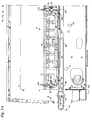
- FIGURE 1 An exemplary machine according to the present invention is shown generally by reference numeral 10 in FIGURE 1, 2 and 4.
- the machine 10 is preferably adapted to be used with a catch tray 11, or a conveyor (FIGURES 1 and 3).
- Media elements A (see FIGURE 1) to be addressed are fed in at the entry end 12 of the machine 10, are engaged by the feeding means 13 to be fed to the transport means 14, and ultimately discharged from the exit end 15 of the machine 10.
- the transport means 14 moves the discrete media elements past a plurality of print heads, such as a first group of print heads 16, and a separate print head 17 (see FIGURES 2 and 4).
- the media elements A may comprise envelopes, cards, flats, or newspapers, or the like.
- the media elements may have size ranging from 3 x 5 inches up to 12 1/4 x 24 inches, with a thickness of up to 1/8th inch. Except for details of operation of the feed rollers, the details of the selector bar, and the positioning of sensors, the inlet 12 and feeding means 13 are substantially identical to those shown in U.S. Patent No. 4,858,907, the disclosure of which is incorporated by reference herein.
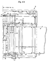
- the positions of the heads 16 may be adjusted with eccentric screws 19 moving the heads as pins 18 move in elongated slots 18′.
- a substrate 20 is provided upon which the media to be printed rests. Exteriorly of the substrate 20 (that is upstream thereof in the direction of the media transport 21) is a bin extension 22, having a support surface 23 thereof that makes an angle with respect to the substrate 20 so as to be effective to take some of the weight of the stack media elements off the bottom element which engages the substrate 20.
- the substrate 20 cooperates with the feed wall 23 against which the leading edges of the media elements are stacked.
- a first or upper feed roller 24 Adjacent the substrate 20 in the direction of transport 21 is a first or upper feed roller 24 which preferably has a non-circular (e.g., rounded apex triangle) cross-sectional configuration, and it is rotatable about a shaft 25 extending in a horizontal dimension essentially transverse to the direction of transport 21.
- the direction of transport 21 preferably is also horizontal.
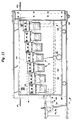
- the shaft 25 is connected to a clutch 26 (seen schematically in FIGURE 11) mounted by a clutch bracket 27 (see FIGURE 4), the clutch being connected up to a motor 28 (see FIGURE 11) for powering it.
- the roller 30 Downstream of the first feed roller 24 in the direction of transport 21 is the support surface 29, and then next to that a second or lower feed roller 30.
- the roller 30 is mounted for rotation about shaft 31, the shaft 31 being parallel to the shaft 25 perpendicular to the direction of transport 21.
- the shaft 31 is connected up to a second clutch 32 (see FIGURE 11) distinct from the first clutch 26, but also powered by motor 28.
- the clutch 32 is also preferably mounted by bracket 27.
- the selector bar 33 is mounted above the second feed roller 30 in operative association therewith.
- the selector bar 33 does not rotate, but rather provides a stationary guide for singulating the media elements A during guiding of the media elements from the surface 29 into operative association with the rotating periphery of the second feed roller 30.
- the selector bar 33 preferably has a first abrasive strip 34 on the outer periphery thereof, and positioned as illustrated in FIGURE 2 -- that is, just above and to the inlet side of the topmost rotating portion of the circumference of the feed roller 30.
- the abrasive strip 34 may be any conventional abrasive material that is bound with an adhesive or the like to the external surface of the bar 33, and extends essentially parallel to the shaft 31. Since the abrasive of the strip 34 will eventually be worn away, it is preferable to provide a second abrasive strip 35 on a circumferential portion of the selector bar 33 remote from (e.g., 180°) the strip 34 so that the selector bar 33 may be repositioned with the strip 35 in place of the strip 34, and thereby the life of the selector bar 33 -- before it need be sent back to the factory for refurbishment -- may be doubled.
- the selector bar 33 in one exemplary embodiment comprises an outer tubular component which has the abrasive strips 34, 35 thereon and includes an inner eccentric shaft 36 which engages the exterior tube of the bar 33. Rotation of the eccentric shaft 36 effects movement of the bar 33 toward and away from the second feed roller 30 in dimension 37 (see FIGURE 2), in mounting slots 38 within side plates 39 mounting the selector bar 33. This allows adjustment of the spacing between the bar 33 and the second feed roller 30 to accommodate media elements A of different thicknesses, e.g., from extremely thin paper sheets, to newspapers up to 1/8th inch thick.
- the transport elements within the section 14 preferably comprise a plurality of spaced (in the dimension of elongation of the shafts 25, 31) endless transport belts 42 which are mounted at the first end thereof in the transport direction 21 by an idler roller 43, and at the furthest end thereof in the transport direction 21, adjacent the discharge 15, by a powered roller 44.
- the axes of rotation of the rollers 43, 44 are parallel to the shafts 25, 31 (i.e., substantially perpendicular to the transport direction 21).
- the axis of rotation of the drive roller 44 is defined by shaft 45 (see FIGURE 4), which is connected to a belt and pulley assembly 46 or the like to the motor 28.
- a guide assembly 48 may be provided above the inlet portions of the belts 42 to help guide media element A into the transport section 14, and in order to assist in clearing media elements from the feeding section 13 to the transport section 14 while preventing slippage with respect to the belts 42, upper and lower pinch rollers 49 and 50 preferably are provided.
- the pinch rollers 49, 50 preferably are constructed such as disclosed in U.S. Patent No. 4,858,907, being rotatable about shafts 51, 52 which are parallel to the rollers 43, 44 and shafts 31, 25, with loop springs 53 (see FIGURE 4) at opposite ends thereof biasing the shafts 51, 52 and the rollers 49, 50 toward each other -- except that the loop springs 53 exert the same force, instead of differential forces as in said patent.
- the shaft 51 is mounted in a vertically-elongated slot (not shown) inside plates 39 so that it may move toward and away from the roller 50, under the bias of loop springs 53 to automatically accommodate media elements A of different thicknesses.
- the surface of at least one of the elements 49, 50 is deformable (e.g., has an elastomeric material thereon).
- first and second photosensors 55, 56 mounted just downstream of the pinch rollers 49, 50 in the transport direction 21 is a third photosensor 57. These photosensors sense the position of media elements A, or the leading and trailing edges thereof, to control various components through a controller 58 (see FIGURE 11), as will be hereinafter described.
- transport wipers are provided.
- the pinch rollers 49, 50 feed each of the media elements A into operative association with the transport wipers.
- an entry transport wiper 59, one or more (e.g. four) main transport wipers 60 (e.g. 60, 60′), and one or more exit transport wipers 61 (e.g. 61, 61′) are provided.
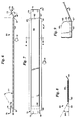
- FIGURES 6 through 10 Details of exemplary transport wipers according to the invention are illustrated in FIGURES 6 through 10.
- the main transport wiper 60 is illustrated most clearly in FIGURES 6 through 9, and main wiper 60′ is seen in FIGURES 2a and 13 while the trailing wiper 61 is illustrated in FIGURES 10 and 13.
- the only significant difference between the wipers 60, 60′, 61, 61′ is their length, width, and shape.
- the entry transport wiper 59 is like the wipers 60, 60′, 61, 61′ except that it does not have a trailing lever.
- the transport wiper 60 comprises a plate 62 having a very smooth bottom surface, adapted to engage the media element A and/or belt 42.
- a particularly desirable material is stainless steel, e.g., a .006 inch thick stainless steel plate with a very smooth bottom surface finish. While the dimensions are not particularly critical, the plate 62 typically could have a width of about 1.15 inches, approximately the width (or more than) one of the belts 42 (e.g., the belts 42 may have a width of about one inch and a spacing between them of about one inch). It is necessary for the width of the plate 62 is greater than the spacing between the belts 42.
- the side edges of the plate 62 are turned up to form flanges 63 which make a positive angle 64 (e.g., about 30°) with respect to the horizontal so that if the wiper assemblies 60, 60′, 61, 61′ are moved in a horizontal dimension parallel to the rollers 43, 44 (perpendicular to the side edges of the belts 42), they will not engage the edges of the belts and cause damage.
- the top surface of each of the plates 62 preferably has a sound dampening material, e.g., an elastomeric or acoustical material, 65 provided thereon to minimize vibration noise.
- the leading and trailing ends of the flanges 63 are radiused, as illustrated at 66 in FIGURE 9.
- the plates 62 have a first end 67 which is the leading end in the direction of travel 21 of the media elements A, and a second end 68 which is the trailing end in the transport direction 21.
- the plate 62 is mounted so that the leading end 67 thereof may be cammed upwardly by a media element A more easily than the trailing end 68 thereof. This is accomplished by utilizing lever means, such as lever elements 69, 70, mounting the plates 62 to the carriage frame 71 for the print heads 16.
- the leading end lever 69 preferably is formed with a leaf spring material or the like, and has the leading end thereof attached by screws passing through opening 72 (see FIGURE 7) into the carriage 71, the main body of the lever 69 extending rearwardly downwardly therefrom to connection to the front of the plate 62 (or being integral therewith), and making an angle 73 with respect to the transport direction 21.
- the trailing lever also is formed of leaf spring material, or the like, and has a mounting portion 74 thereof which is connected by screws passing through opening 75 (see FIGURE 7) to the carriage 71, with the actual lever arm portion 76 thereof extending from the leading edge of the mounting plate 74 to the trailing edge 68 of the plate 62.
- the lever 76 makes an angle 77 with respect to the transport direction 21.
- Levers 69, 76 need not be articulated, but rather pivot points will necessarily be provided at the portions 78, 79, 80 and 81 thereof. While the angles 73, 77 will change as the plate 62 pivots about lever arms 69, 70, initially the angle 73 is substantially less than the angle 77 so that the leading edge 67 of the plate 62 is easily cammed upwardly by a discrete media element A, while as the element A moves in the direction of transport 21, the downward biasing force provided by the plate 62 to clamp it to the belt 42 increases. In one exemplary embodiment, the angle 77 is about 30°, while the angle 73 is about 15°.
- Figure 10 schematically illustrates operation of one of the transport wipers, in this case, the exit transport wiper 61, the movement of the longer entry lever 69, shorter exit lever 76 and plate 62 with respect to the belt 42 being shown as a media element A (e.g., envelope) to be printed cams the wiper plate 62 upwardly as it is moves in the transport direction 21.
- the initial position of the wiper 61 is shown in dotted line, and its cammed upward position in solid line in FIGURE 10.
- the main frame or carriage 71 for mounting the print heads 16 mounts all of the print heads except for one (that is, the seven print heads 16 illustrated in FIGURES 4a and 4b), while the second carriage 84 mounts the other print head 17, having an extension 83 (see FIGURES 13 and 14) going around carriage 71.
- a pivoted cover 86, pivoted about a pivot pin 87, may be provided for mounting the print heads 16, and which can be swung up about the pivot pin 87 using handle 86′ for pivoting the print heads 16 out of the way, for cleaning.
- the print heads 16 print seven address lines, while the print head 17 either prints an eighth address line, or bar code. It is held adjacent the bottom of the media to be printed and away from the heads 16 when printing bar code. Where the printer 17 prints bar code, it is preferred that the controller 58 scan the address information fed to the machine 10 for valid zip code information, and create the bar code from the zip code information and thereby control the printer 17. This, and various other control aspects of the components according to the invention, may be the same as in FIGURES 11 through 13 of said U.S. Patent No. 4,858,907.
- the carriage 71 is mounted for movement in the dimension 85 by carriage support tubes 88, 89.
- a scale 90 preferably is provided on the support tube 89 to indicate the positioning of the carriage 71 along the tubes 88, 89 --i.e., in the dimension 85.
- the transport wipers 60, 60′, 61, 61 are preferably provided on both side edges of the carriage 71 (that is, on opposite sides of the print heads 16), as seen in FIGURE 13. Since the wipers are wider than the space between the belts 42, when positioning the carriage 71 in the dimension 85 care need not be taken to see that wipers 59-61 are in substantial registry with a transport belt 42.
- This movement in dimension 85 can be as much as seven inches, allowing precise positioning of the printing area for a wide variety of different types and sizes of printing media A.
- the carriage 84 can be slid on tubes 88, 89 too, and the carriage 84 may be moved relative to carriage 71 to position head 17 to print eight lines of address, if desired.
- the shafts 91, 92 have the same eccentricity as the shaft 36 associated with selector bar 33, and all of the shafts 36, 91, 92 are mounted together so that the spacing between the print heads 16 and the transport belts 42 (and the media A supported thereby), as well as the spacing between the selector bar 33 and the second feed roller 30, will always be proportional, e.g., the spacing between the selector bar 33 and the feed roller 30 will be substantially equal to the thickness of the media element, while the spacing from the print head 16 on the top of the transport belts 42 will be thickness of the media element A plus the desired distance the print head 16 is normally provided above the top surface of the media element A.
- the simultaneous adjustment of the spacings of the elements 33, 88, 89 is accomplished by tying the tubes 88, 89 together with an anti-backlash chain 94 (see FIGURE 4a) extending between sprockets 95, 96 connected to shaft 91, 92 by adjustable locking collars 97, and by tying shaft 36 to shaft 92 utilizing anti-backlash chain 98 connected between sprockets 99, 100, again with an adjustable locking collar 97. Then, by rotating control knob 101, connected to shaft 36, the shafts 36, 91 and 92 are simultaneously rotated a known amount so that the desired proportional spacings are always maintained.
- the carriage locks 104, 105 are provided mounted on the carriage 84, 71, respectively, in association with the tubes 89, 88, respectively, to hold carriages 84, 71, respectively, in a position in which they have been moved in the dimension 85 with respect to the tubes 88, 89.
- the carriage locks 104, 105 are rotated 90° from the position illustrated in FIGURE 2a, they hold carriages 71 and 84 in place with respect to the tubes 88, 89, while in the position as illustrated in FIGURE 2a, they allow relative movement therebetween.
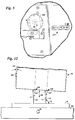
- FIGURE 12 schematically illustrates the particular positioning of each of the ink jet print heads 16 (and 17) according to the invention with respect to the direction of transport 21, and the vertical 93.
- FIGURE 12 schematically illustrates a conventional ink jet print head 16 having a plurality of orifices or nozzles 107 arranged in banks 108, 109 in the dimension 85. If the nozzles 107 are mounted so that a stream of ink issuing therefrom -- illustrated by line 110 in FIGURE 12 -- is perpendicular to the media element A, rebounded ink -- illustrated by reference numeral 111 in FIGURE 12 -- will rebound directly up to the orifices or nozzles 107, and eventually clog them unless some sort of a wiper is provided.
- the necessity for a wiper is avoided according to the invention by mounting the orifices 107 so that the rebounded ink path 111 does not impact them. This is accomplished by mounting the print head 16 so that the center lines of the banks 108, 109 of orifices or nozzles 107 (which are in line with the ink streams 110) are not perpendicular to the direction of travel 21 (i.e., the surface of the transport belts 42). That is, there is a small anglular deviation 112 from the vertical 93, which angle 112 may be about 3°. That means that the angle 113 of the ink stream 110 with respect to the direction of transport 21 is about 87° (90° minus 3°).
- the elements A preferably are discharged from the belts 42 onto the belts 116, which extend between the drive roller 44 and an idler roller 117.
- an exit idler roller 118 is preferably associated with the belts 116 and idler roller 117 to control the orientation of the elements A as they move out of the discharge end of the machine 10 into the bin or tray 11.
- the exit idler roller 118 rotates about an axis elongated in the dimension 85, being mounted at one end thereof by a weight 119 connected to lever arm 120 which in turn is connected by pivot pin 121 to tube 89.
- the idler exit roller 118 is right at the very end of the belt 116 so it has a tendency to keep the discharge media elements substantially horizontal until just before final discharge thereof. This means that they will not have a tendency to drape down into the bin 11, and possibly have the leading edge thereof dragged across the printed address information on the previously discharged media element A, which would result in smudging thereof.
- the bin 11 preferably has an adjustable backstop 122 which is held in place along the tray sidewalls 123 by locking tab or tabs 124, the backstop 122 being positioned so that media elements A exiting the machine 10 hit it and drop vertically down into the bin 11, again to minimize the possibility of smearing of wet ink applied by the print heads 16, 17.
- FIGURE 5 shows a friction brake 127 which may be associated with the first feed roller 24 to stop rotation of the first feed roller 24 due to its own inertia, thereby preventing misfeeding of short media elements A.
- FIGURE 5 also illustrates a locating plate 128 associated with eccentric bar 36.
- a similar locating plate is associated with eccentric shafts 91, 92.
- Such locking plates 128 hold the shafts 36, 91, 92 in the predetermined relative positions in which they have been placed at the factory for the appropriate parallelness with the elements beneath them. Thus, they allow removal of the selector bar 33 and tubes 88, 89, and reinstallation, without requiring new parallelness adjustments.
- the apparatus according to the invention may also include an encoder 129 (see FIGURE 11) mounted on the transport belt idler shaft so that any belt slippage which may occur on the driven belt shaft will not affect printing quality. Also, a motor encoder 133 (see FIGURE 2) may be provided for controlling the motor speed -- that is, keeping the motor speed constant.
- a stack of envelopes is placed on the support surface 20 and extension 23, and the machine is started.
- the motor 28 drives clutches 26 and 32 so that the feed rollers 24, 30 start rotating, and the bottom envelope in the stack is engaged by the first feed roller 24 and driven in the transport direction 21, so that it impacts the abrasive strip 34 on selector bar 33, and moves into contact with the upper rotating surface of the second feed roller 30.
- the second feed roller 30 drives it over the bridge 41, and under the photosensors 55, 56 into contact with the pinch rollers 49, 50.
- the leading edge of the envelope passing past photosensor 56 causes the controller 58 to disengage the clutch 26 so that the first feed roller 24 no longer rotates, and it is quickly brought to a halt by the friction brake 127.
- the second feed roller 30 substantially continues feeding, however, and when the trailing edge of the envelope passes the photosensor 55, the controller 58 engages the clutch 26 to again start rotation of the first feed roller 24, to start the movement of the next envelope in the stack in the transport direction 21.
- Feed roller 30 operation may be arrested for a short period of time, however, if desired, using clutch 32.
- the pinch rollers 49, 50 hold the envelope tightly on the belts 42 until the trailing edge thereof clears the feed rollers 24, 30 and the leading edge is guided under the entry transport wiper 59.
- the spacings between the rollers 24, 30, and 30, 49/50, and between the rollers 49/50 and the leading transport wiper 59 are preferably shorter than the shortest length media (e.g., 3 x 5 cards) intended to be transported.
- the feeding action is so positive according to the invention that even media less than 5 inches in length can be transported and printed.
- the controller 58 controlling the print heads 16, 17 in response to the sensed position so that ink is issued from the nozzles or orifices 107 of the print heads 16, 17 and applied to the envelope in appropriate address lines. Because of the tilted orientation of the print heads 16, 17 the orifices 107 therein will not clog as a result of rebounding ink.
- the envelope passes under the transport wiper plate 62 of wipers 60, 60′ -- which is relatively easy due to the small angle 73 -- the force holding it increases along the length of the wiper plate 62, so that the envelope is held precisely in place, without any slippage with respect to belts 42, until it passes through the entire printing operation.
- the envelope passes to belts 116 and it is held by exit roller 118 so that it is substantially horizontal until almost to the point of impact on backstop 122, at which time it falls downwardly into the tray 11, without having smeared the earlier printed envelope.
- control knob 101 When it is desired to print envelopes of a different size or thickness, the control knob 101 is rotated to provided the desired gaps between the selector bar 33 and second feed roller 30, and between the print head orifices 107 and transport belts 42; and the levers 104, 105 are operated to allow movement of the carriages 71, 84 in the dimension 85 to properly position the print heads 16, 17 with respect to the new size of envelopes so that the address will be printed in the correct location.
- the selector bar 132 (corresponding to the previously described selector bar 33) has a plurality of resilient, annular friction rings, e.g., rubber O-rings 134, spaced axially along the outer periphery thereof in relatively shallow grooves 136 (one partially shown in Fig. 15) formed in the exterior surface of the selector bar, as best seen in FIGURES 3 and 4.
- the O-rings 134 employed in place of abrasive strips 34, 35, are positioned just above the topmost rotating portion of the circumference of the feed roller 138 mounted on shaft 141 (corresponding to previously described feed roller 30 and shaft 31, respectively). The manner in which this positioning is accomplished is explained below.
- Feed roller 138 is formed with a like number of peripheral grooves 139 correspondingly axially spaced along the feed roller 138 so as to receive the radially protruding O-rings 134.
- an arrangement is provided which permits the selector bar 132 to be rotated about its axis so that unused serpents of the O-rings 134 can be located to face. the feed roller 138, allowing this improved feed mechanism to last four to five times longer than the previously disclosed selector bar before the expendable elements, i.e., the O-rings, need replacement.
- the selector bar 132 preferably comprises an outer tubular component 140 which has a pair of end caps 142, 144, each having an elongated slot 146 and a pair of diametrically opposed guide pins 148, the width of the slot 146 sized to snugly receive an interior, eccentric shaft assembly 150 which, when rotated, effects movement of the bar 132 toward or away from the second feed roller 138 (as in dimension 37 in FIGURE 2).
- the selector bar 132 is confined to substantially vertical movement by reason of the sliding engagement of pins 148 within substantially vertical slots provided within the machine plate 154 on the left side of the selector bar (Fig.
- selector bar tube 140 is formed with four axially extending slits 158 (three shown) spaced equally about the circumference of the tube, and received over a stepped diameter adjustment insert 160 which, in turn, receives the end cap 144.
- the slit configuration allows the selector bar to be tightly clamped to the adjustment insert as described further below.
- the larger diameter end 162 of the adjustment insert 160 is provided with two, diametrically opposed notches 164 (one shown in Fig. 16) which are designed to receive a corresponding pair of anti-rotation tabs 166 formed on the end cap 144.
- machine plate 156 is formed with an aperture for receiving the selector bar mounting apparatus.
- an access plate 168 of generally elliptical or rounded elongated shape is provided with a similarly shaped projecting portion 170, the inside face of which includes vertically aligned elongated slots 172 which receive the guide pins 148 of end cap 144, thereby permitting the cap 144 and selector bar 132 to move towards and away from second feed roller 138 via rotation of the shaft assembly 150 as described above.
- locator plate 174 having an aperture 180 shaped to receive projecting portion 170 of plate 168.
- Machine plate 156 has an identical aperture to receive projecting portion 170 of plate 168.
- the access plate 168 is held to the front surface of machine plate 156 with two screws passing through slots 178′ and slots 178 of the locator plate 174.
- the locator plate 174 is fastened to the front surface of machine plate 156 with two screws passing through slots 176.
- Engagement of guide pins 148 of end cap 174 with slots 172 of access plate 168 and engagement of anti-rotation tabs 166 of end cap 144 with the notches 164 in adjustment insert 160 prevent relative rotation between access plate 168, end cap 144 and adjustment insert 160.
- the mounting arrangement permits vertical movement of the selector bar 132 upon rotation of shaft assembly 150, but prevents relative rotation between adjustment insert 160, end cap 144 and access plate 168 on the one hand, and locator plate 174 and machine plates 154, 156 on the other.
- the selector bar 132 (with end cap 144) may be slidably removed from the machine for maintenance and/or replacement.
- Locator plate 174 will remain fixed to the machine plate 156 to insure proper parallel alignment (relative to feed roller 138) of the selector bar upon reassembly.
- the end cap 142 on the left hand side of the selector bar 132 as viewed in FIGURE 15 is also provided with guide pins (not shown) but without the anti-rotation tabs 166. This arrangement permits relative rotation between the selector bar 132 and end cap 142 for the purpose described below.
- a conventional locking collar or clamp 182 is slidably received over the tubular component 140 to a position where it overlies slits 158 of the tube and the adjustment insert 160.
- locking collar 151 when tightened, prevents any rotation of selector bar 132 relative to end caps 142, 144 and adjustment insert 160, while allowing vertical movement of the selector bar assembly via rotation of shaft assembly 150 for the purpose of adjustment toward or away from feed roller 138.
- the collar 182 may be loosened, however, and selector bar 132 may then be rotated relative to end caps 142, 144 as well as the adjustment insert 160 so that fresh or unused portions of the O-rings 134 can be rotated to a position adjacent the second feed roller 138.
- a permanent indicator 184 is provided on the end cap 142.
- scale markers 186 are provided on the tubular portion 140, the distance between adjacent scale markers corresponding to the amount of rotation required to present fresh portions of the O-rings 134 to the feed roller 138.
- the second embodiment incorporated in the machine earlier described with respect to the first embodiment, operates as follows.
- a stack of envelopes (media A) is placed on the support surfaces 20, 26 and extension 23, and the machine is started.
- the motor driven clutches cause feed rollers 24, 138 to start rotating, and the bottom envelope in the stack is engaged by the first feed roller 24 and driven in the transport direction 21, so that it impacts the O-rings 134 on selector bar 132, and moves into contact with the upper rotating surface of the second feed roller 138.
- the selector bar 132 is adjusted downwardly toward the grooved second feed roller 138 so that a series of bends 188 are created across the width of the media being fed as indicated in Figure 20, by reason of the cooperation of O-rings 134 and grooves 139.
- Associated retarding friction between the O-rings 134 and the piece of media A′ next to the bottommost piece of media A ⁇ is greater than the friction holding the two pieces of media A′, A ⁇ together.
- the driving friction between the feed roller 138 and the bottom piece of media A ⁇ is also greater than the friction holding the bottom two pieces A′, A ⁇ together. Accordingly, the bottom piece A" is fed by itself and the next piece A′ is held back by the O-rings 134.
- the O-rings 134 hold back the leading edge 190 of the piece of media B next to the bottom of the stack while the bottom piece B′ is fed to the feed roller 138.
Landscapes
- Engineering & Computer Science (AREA)
- General Engineering & Computer Science (AREA)
- Physics & Mathematics (AREA)
- General Physics & Mathematics (AREA)
- Theoretical Computer Science (AREA)
- Ink Jet (AREA)
- Sheets, Magazines, And Separation Thereof (AREA)
Applications Claiming Priority (4)
| Application Number | Priority Date | Filing Date | Title |
|---|---|---|---|
| US596040 | 1990-10-11 | ||
| US07/596,040 US5094554A (en) | 1990-10-11 | 1990-10-11 | Addressing machine |
| US689330 | 1991-04-23 | ||
| US07/689,330 US5163669A (en) | 1990-10-11 | 1991-04-23 | Paper feed mechanism having an adjustable restrainer |
Publications (2)
| Publication Number | Publication Date |
|---|---|
| EP0480719A2 true EP0480719A2 (de) | 1992-04-15 |
| EP0480719A3 EP0480719A3 (en) | 1992-08-12 |
Family
ID=27082443
Family Applications (1)
| Application Number | Title | Priority Date | Filing Date |
|---|---|---|---|
| EP19910309313 Ceased EP0480719A3 (en) | 1990-10-11 | 1991-10-10 | Addressing machine |
Country Status (3)
| Country | Link |
|---|---|
| US (1) | US5163669A (de) |
| EP (1) | EP0480719A3 (de) |
| CA (1) | CA2053369A1 (de) |
Cited By (1)
| Publication number | Priority date | Publication date | Assignee | Title |
|---|---|---|---|---|
| EP0573272A3 (en) * | 1992-06-04 | 1994-05-18 | Tokyo Electric Co Ltd | Sheet delivery mechanism for a printer |
Families Citing this family (13)
| Publication number | Priority date | Publication date | Assignee | Title |
|---|---|---|---|---|
| DE69116749T2 (de) * | 1990-07-06 | 1996-09-19 | Canon Kk | Blattzuführer |
| US5538234A (en) * | 1993-04-02 | 1996-07-23 | Data Pac Mailing Systems Corp. | Automatic mailing machine |
| US5340097A (en) * | 1993-04-02 | 1994-08-23 | Data Pac Mailing Systems Corp. | Automatic mailing machine |
| US5401013A (en) * | 1993-09-16 | 1995-03-28 | Bryce Office Systems, Inc. | Addressing machine feed gap setting |
| US5397107A (en) * | 1993-11-29 | 1995-03-14 | Pitney Bowes Inc. | Apparatus for separating and feeding sheets from a stack thereof |
| DE29519061U1 (de) * | 1995-12-01 | 1996-01-25 | Mathias Bäuerle GmbH, 78112 St Georgen | Einstellbare Schleuse für Papierbogen o.dgl. |
| US5767452A (en) * | 1995-12-15 | 1998-06-16 | Data Pac Mailing Systems Corp. | Mailing machine |
| GB2312667B (en) * | 1996-05-02 | 2000-09-06 | Lexmark Int Inc | Sheet separator |
| FR2758763B1 (fr) * | 1997-01-24 | 1999-04-16 | Neopost Ind | Machine compacte de traitement de courrier a chemin de transport particulier |
| US5967504A (en) * | 1997-08-15 | 1999-10-19 | Data Pac Mailing Systems Corp. | Envelope feeder |
| US6978993B2 (en) * | 2003-10-16 | 2005-12-27 | Pitney Bowes Inc. | Method and device for rotating a frictional surface in a friction feeder |
| GB2462262A (en) * | 2008-07-29 | 2010-02-03 | Neopost Technologies | Adjustable vacuum sheet feeder with adjustable sheet retaining device |
| US8186676B2 (en) * | 2008-10-09 | 2012-05-29 | Xerox Corporation | Apparatus and method for reducing vibration and noise in a printer |
Family Cites Families (17)
| Publication number | Priority date | Publication date | Assignee | Title |
|---|---|---|---|---|
| US3838851A (en) * | 1972-02-22 | 1974-10-01 | Addressograph Multigraph | Bottom sheet feeder |
| CA1116647A (en) * | 1978-10-20 | 1982-01-19 | John A. Long | Inclined stack surface contacting conveyor bottom sheet feeder with warping means |
| FR2453809A1 (fr) * | 1979-04-10 | 1980-11-07 | Transac Develop Transactions A | Procede et dispositif de separation et d'extraction une a une de feuilles empilees |
| JPS5633331A (en) * | 1979-08-21 | 1981-04-03 | Laurel Bank Mach Co Ltd | Gate member of paper sheet delivering apparatus |
| US4437658A (en) * | 1981-07-30 | 1984-03-20 | Profold, Inc. | Bottom sheet feed system |
| US4728095A (en) * | 1983-06-20 | 1988-03-01 | Pitney Bowes Inc. | Separator for a document feeder |
| JPS61235330A (ja) * | 1985-04-09 | 1986-10-20 | Nec Corp | フリクシヨン繰り出し方式における自動強制重送防止機構 |
| JPH0717286B2 (ja) * | 1985-08-10 | 1995-03-01 | キヤノン株式会社 | シ−ト給送装置 |
| EP0287631B1 (de) * | 1986-10-14 | 1993-06-23 | Bryce Office Systems, Inc. | Drucksystem für adressen und strichkodes auf briefumschlägen |
| US4858907A (en) * | 1986-10-14 | 1989-08-22 | Bryce Office Systems, Inc. | System for feeding envelopes for simultaneous printing of addresses and bar codes |
| JPS63258330A (ja) * | 1987-04-13 | 1988-10-25 | Omron Tateisi Electronics Co | 紙葉類の繰出し制御装置 |
| JPS6432031A (en) * | 1987-07-27 | 1989-02-02 | Nippon Carbureter | Carburetor |
| JPH029330A (ja) * | 1987-10-30 | 1990-01-12 | Sanko Kagaku Kogyo Kk | 発煙装置 |
| JP2596040B2 (ja) * | 1988-02-13 | 1997-04-02 | オムロン株式会社 | 紙葉類の繰出し装置 |
| JPH0243141A (ja) * | 1988-07-30 | 1990-02-13 | Nec Corp | シート分離装置 |
| KR930000181B1 (ko) * | 1989-02-02 | 1993-01-11 | 도쿄덴기 가부시기가이샤 | 인자기 |
| US4991831A (en) * | 1989-08-14 | 1991-02-12 | Green Ronald J | Paper sheet feeding apparatus |
-
1991
- 1991-04-23 US US07/689,330 patent/US5163669A/en not_active Expired - Fee Related
- 1991-10-10 EP EP19910309313 patent/EP0480719A3/en not_active Ceased
- 1991-10-11 CA CA002053369A patent/CA2053369A1/en not_active Abandoned
Cited By (2)
| Publication number | Priority date | Publication date | Assignee | Title |
|---|---|---|---|---|
| EP0573272A3 (en) * | 1992-06-04 | 1994-05-18 | Tokyo Electric Co Ltd | Sheet delivery mechanism for a printer |
| US5409209A (en) * | 1992-06-04 | 1995-04-25 | Tokyo Electric Co., Ltd. | Sheet delivery mechanism for a printer |
Also Published As
| Publication number | Publication date |
|---|---|
| CA2053369A1 (en) | 1992-04-12 |
| US5163669A (en) | 1992-11-17 |
| EP0480719A3 (en) | 1992-08-12 |
Similar Documents
| Publication | Publication Date | Title |
|---|---|---|
| EP0480719A2 (de) | Adressierungsgerät | |
| US5192141A (en) | Multi-dimensional media printer with media based registration and free edge printing | |
| US5094554A (en) | Addressing machine | |
| US5216442A (en) | Moving platen architecture for an ink jet printer | |
| US7168700B2 (en) | Sheet feeder apparatus and method with throughput control | |
| US5180154A (en) | Method and apparatus for changing the direction of motion of flat articles | |
| US5850235A (en) | Printer | |
| US4078790A (en) | Sheet collector | |
| GB1569370A (en) | Sheet feeding and receiving apparatus for directing sheetsof paper to and receiving sheets from a platen of an office machine | |
| US7156390B2 (en) | Devices for aligning sheets | |
| US7232123B2 (en) | Apparatus for conveying sheets through a printing machine | |
| US6817608B2 (en) | Method and apparatus for stacking mailpieces in consecutive order | |
| US3944210A (en) | Ticket counter and endorser | |
| US8353510B2 (en) | Variable media feed system and printhead apparatus | |
| US6089773A (en) | Print media feed system for an ink jet printer | |
| US7762538B2 (en) | Gatherer stitcher with variable chain pitch and method for adapting an endless gatherer chain to a format of a product | |
| US3998451A (en) | Ticket counter and endorser | |
| EP1661837B1 (de) | Bogenausgabesystem | |
| US4305655A (en) | Duplex printer and method of printing | |
| US5329302A (en) | Tapered platen roller for thermal printer | |
| EP0844535B1 (de) | Bildaufnahmegerät mit einer Papierführung | |
| US6966711B2 (en) | Dynamic registration device for mailing system | |
| US5265866A (en) | Device for feeding and further processing printing material in sheet-fed rotary printing presses | |
| EP0729842A2 (de) | Medientransport bei einem Tintenstrahldrucker | |
| CA2054515C (en) | Method and apparatus for changing the direction of motion of flat articles |
Legal Events
| Date | Code | Title | Description |
|---|---|---|---|
| PUAI | Public reference made under article 153(3) epc to a published international application that has entered the european phase |
Free format text: ORIGINAL CODE: 0009012 |
|
| AK | Designated contracting states |
Kind code of ref document: A2 Designated state(s): AT BE CH DE DK ES FR GB GR IT LI LU NL SE |
|
| PUAL | Search report despatched |
Free format text: ORIGINAL CODE: 0009013 |
|
| AK | Designated contracting states |
Kind code of ref document: A3 Designated state(s): AT BE CH DE DK ES FR GB GR IT LI LU NL SE |
|
| 17P | Request for examination filed |
Effective date: 19921020 |
|
| 17Q | First examination report despatched |
Effective date: 19940311 |
|
| STAA | Information on the status of an ep patent application or granted ep patent |
Free format text: STATUS: THE APPLICATION HAS BEEN REFUSED |
|
| 18R | Application refused |
Effective date: 19950731 |