EP0480721A2 - Strukturschwingungen kompensierende Motoranordnung mit zwei Rücken an Rücken angeordneten Wechselstrommotoren - Google Patents
Strukturschwingungen kompensierende Motoranordnung mit zwei Rücken an Rücken angeordneten Wechselstrommotoren Download PDFInfo
- Publication number
- EP0480721A2 EP0480721A2 EP91309315A EP91309315A EP0480721A2 EP 0480721 A2 EP0480721 A2 EP 0480721A2 EP 91309315 A EP91309315 A EP 91309315A EP 91309315 A EP91309315 A EP 91309315A EP 0480721 A2 EP0480721 A2 EP 0480721A2
- Authority
- EP
- European Patent Office
- Prior art keywords
- stator core
- stator
- annular
- structures
- rotor
- Prior art date
- Legal status (The legal status is an assumption and is not a legal conclusion. Google has not performed a legal analysis and makes no representation as to the accuracy of the status listed.)
- Withdrawn
Links
Images


Classifications
-
- H—ELECTRICITY
- H02—GENERATION; CONVERSION OR DISTRIBUTION OF ELECTRIC POWER
- H02K—DYNAMO-ELECTRIC MACHINES
- H02K5/00—Casings; Enclosures; Supports
- H02K5/24—Casings; Enclosures; Supports specially adapted for suppression or reduction of noise or vibrations
-
- H—ELECTRICITY
- H02—GENERATION; CONVERSION OR DISTRIBUTION OF ELECTRIC POWER
- H02K—DYNAMO-ELECTRIC MACHINES
- H02K1/00—Details of the magnetic circuit
- H02K1/06—Details of the magnetic circuit characterised by the shape, form or construction
- H02K1/12—Stationary parts of the magnetic circuit
- H02K1/18—Means for mounting or fastening magnetic stationary parts on to, or to, the stator structures
- H02K1/182—Means for mounting or fastening magnetic stationary parts on to, or to, the stator structures to stators axially facing the rotor, i.e. with axial or conical air gap
-
- F—MECHANICAL ENGINEERING; LIGHTING; HEATING; WEAPONS; BLASTING
- F16—ENGINEERING ELEMENTS AND UNITS; GENERAL MEASURES FOR PRODUCING AND MAINTAINING EFFECTIVE FUNCTIONING OF MACHINES OR INSTALLATIONS; THERMAL INSULATION IN GENERAL
- F16F—SPRINGS; SHOCK-ABSORBERS; MEANS FOR DAMPING VIBRATION
- F16F15/00—Suppression of vibrations in systems; Means or arrangements for avoiding or reducing out-of-balance forces, e.g. due to motion
- F16F15/10—Suppression of vibrations in rotating systems by making use of members moving with the system
-
- H—ELECTRICITY
- H02—GENERATION; CONVERSION OR DISTRIBUTION OF ELECTRIC POWER
- H02K—DYNAMO-ELECTRIC MACHINES
- H02K1/00—Details of the magnetic circuit
- H02K1/06—Details of the magnetic circuit characterised by the shape, form or construction
- H02K1/22—Rotating parts of the magnetic circuit
- H02K1/28—Means for mounting or fastening rotating magnetic parts on to, or to, the rotor structures
-
- H—ELECTRICITY
- H02—GENERATION; CONVERSION OR DISTRIBUTION OF ELECTRIC POWER
- H02K—DYNAMO-ELECTRIC MACHINES
- H02K16/00—Machines with more than one rotor or stator
Definitions
- the present invention relates generally to mechanical vibration reduction and, more particularly, is concerned with a structureborne vibration-compensated motor arrangement having back-to-back twin AC motors.
- AC motors particularly synchronous types, are simple and reliable.
- AC motors are generators of variable frequency structureborne vibrations (or noise) which are difficult to damp and attenuate. It is extremely difficult to greatly reduce the structureborne vibrations over a wide frequency range. This basic problem has been a main factor preventing the use of AC propulsion systems for submarines.
- the structureborne vibrations caused by AC motor operation result from summation of the electromagnetic forces in conductors and magnetic forces in the magnetic stator core, in space and time.
- the vibrations appear at the structural interfaces at the outer periphery of the stator core and at the shaft of the AC motor.
- Sophisticated structural systems which absorb and damp structureborne vibrations over a wide frequency range are required in the stator core support system and at shaft bearings.
- the vibrations are also transmitted along the propulsion shaft to the ship's propellers, requiring special attenuators to minimize this transmission.
- the present invention provides structureborne vibration-compensated motor arrangement designed to satisfy the aforementioned need.
- the approach of the present invention to reducing structureborne vibrations is the provision of a motor arrangement which includes a pair of symmetrical, axial or radial gap, twin AC motors, mounted back-to-back, and constructed as mirror images of one another.
- Annular stator core structures of the twin AC motors are placed precisely adjacent to one another on opposite sides of an annular stator support member mounted to an outer support housing of the motor arrangement.
- the stator core structures are precisely matched as electrical devices in space and time. The axial vibrations are thus exactly the same in each stator core structure and are cancelled out by the other adjacent stator core structure.
- annular rotor field structures of the twin AC motors are supported by annular rotor support members of the motor arrangement being mounted on a common rotatable shaft structure of the motor arrangement.
- the axial vibrations of the rotor field structures are also cancelled out in the same way as the stator vibrations except at the shaft structure mounting the rotor support structures to the shaft.
- the radial vibrations of the stator and rotor structures would also be very small at the housing and shaft structure.
- first and second yieldably resilient means which isolate torsional vibrations of the stator core and rotor field structures respectively from the outer housing and shaft structures of the motor arrangement.
- first and second means are pluralities of yieldably resilient spring bars respectively supporting the annular stator support member on the outer support housing and the annular rotor support members on the shaft structure so as to isolate torsional vibrations of the stator core and rotor field structures respectively from the outer support housing and shaft structure.
- first and second means are yieldably resilient bushings respectively supporting the annular stator support member on the outer support housing and the annular rotor support members on the shaft structure so as to isolate torsional vibrations of the stator core and rotor field structures respectively from the outer support housing and shaft structure.
- Fig. 1 is a fragmentary cross-sectional view of a structureborne vibration-compensated motor arrangement of the present invention having back-to-back twin AC motors arranged to cancel out axial and radial vibration forces.
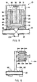
- Fig. 2 is a side elevational view of an annular stator core structure of each of the twin AC motors of the motor arrangement of Fig. 1.
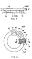
- Fig. 3 is a side elevational view of an annular rotor field structure of each of the twin AC motors of the motor arrangement of Fig. 1.
- Fig. 4 is an enlarged cross-sectional view of the rotor field structure taken along line 4--4 of Fig. 3.
- Fig. 5 is a fragmentary cross-sectional view of an alternative embodiment of the back-to-back twin AC motors of the motor arrangement of the present invention.
- Fig. 6 is a schematical view of the motor arrangement of Fig. 1 with yieldably resilient spring bars isolating torsional vibrations of the stator core and rotor field structures from the outer support housing and the shaft structure of the motor arrangement.
- Fig. 7 is a fragmentary side elevational view of the motor arrangement as seen along line 7--7 of Fig. 6.
- Fig. 8 is a fragmentary side elevational view of the motor arrangement as seen along line 8--8 of Fig. 6.
- Fig. 9 is a schematical view of the motor arrangement of Fig. 1 with yieldably resilient bushings isolating torsional vibrations of the stator core and rotor field structures from the outer support housing and the shaft structure of the motor arrangement.
- the motor arrangement 10 basically includes an outer support housing 12, a rotatable shaft structure 14, and a pair of right and left twin AC motors 16 and 18.
- the shaft structure 14 is composed of a central shaft 20 and an annular hub 22 fixedly attached on and about an annular flange 20A projecting outwardly from and about the central shaft 20 for rotation therewith.
- the right and left twin AC motors 16 and 18 include right and left annular stator core structures 24 and 26, as best seen in Fig. 2, and right and left annular rotor field structures 28 and 30, as best seen in Figs. 3 and 4.
- the right and left stator core structures 24, 26 are mounted by a central annular stator support member 32 which, in turn, is stationarily attached to the outer support housing 12.
- the right and left annular rotor field structures 28, 30 are mounted respectively in spaced relation from the right and left stator core structures 24, 26 by right and left annular rotor support members 34 and 36 at opposite right and left ends of the twin AC motors 16, 18.
- the right and left rotor support members 34, 36 are fixedly mounted to the annular hub 22 of the rotatable shaft structure 14 for rotation therewith such that the right and left rotor field structures 28, 30 rotate relative to the right and left stator core structures 24, 26.
- the right and left twin AC motors 16, 18 of the motor arrangement 10 are mounted with their right and left stator core structures 24, 26 located at a pair of opposite sides of the central stator support member 32 and the right and left rotor field structures 28, 30 are spaced from and located adjacent the respective stator core structures 24, 26, opposite from the central stator support member 32, such that the right and left twin AC motors 16, 18 are arranged back-to-back as mirror images of one another for cancelling out axial and radial vibrations at the outer support housing 12 and the shaft structure 14.
- the housing 12 may be connected to a ship or submarine main structure.
- the stator support member 32 may be composed of metal, or a combination of metal plates, composites and polymer liners to damp and absorb any axial and radial vibrations not cancelled out.
- the stator core structures 24, 26, as seen in Fig. 2, are precisely mounted in near-perfect symmetry to ensure that the structureborne vibrations in time and space are near-perfect mirror images and will therefore cancel out.
- the stator core structures 24, 26 include an annular core ring 38 and windings 40 precisely placed in slots 42 formed in the core ring 38 and connected in parallel to a common power source (not shown).
- the rotor field structures 28, 30 are mounted to the common hub 22 with precise symmetry in the same way as the stator core rings 38.
- the rotor field structures 28, 30 have pole bodies 44 with field windings 46 around them.
- the pole bodies 44 and pole shoes 48 are mounted by the support members 34, 36 and can be constructed using magnetic iron laminations, with a copper or copper alloy damping winding 50 wound in the pole shoe 48.
- the damping winding 50 may be localized in the pole area or be connected into a continuous circumferential winding. The number of poles is determined by the required motor speed and the supply signal frequency.
- the damping winding 50 could also be used as an induction motor starting winding for a direct drive system.
- the axial and radial vibrations in the rotor field structures 28, 30 will be cancelled out at the hub interface, where the rotor support members 34, 36 are connected to the hub 22.
- the field windings 46 are also excited from a common power source (not shown).
- the right and left rotor field structures 28, 30 are spaced axially from the respective right and left stator core structures 24, 26.
- the outer and inner rotor field structures 28A, 30A are spaced radially from the respective outer and inner stator core structures 24A, 26A.
- the hub 22A is arranged substantially perpendicular to the shaft 20 instead of substantially parallel as in first embodiment of Fig. 1.
- bearings 62 are shown in this figure for supporting shaft 20 and it is to be understood that similar bearings (not shown) would support the shaft 20 shown in the other embodiments.
- the back-to-back twin AC motor arrangement 10 will essentially eliminate the axial and radial vibrations generated by the motors at the outer housing 12 and the hub 22, as previously discussed. However, vibratory torques would still act at both housing and hub interfaces, causing substantial structureborne torsional vibrations. To avoid this, torsional vibration isolation is provided in these regions.
- the respective stator support member 32 and rotor support members 34, 36 are mounted respectively to the outer housing 12 and the shaft structure hub 22 by first and second yieldably resilient means which isolate torsional vibration of the stator core structures 24, 26 and rotor field structures 28, 30 respectively from the outer housing and shaft.
- the first and second means are first and second pluralities of yieldably resilient spring bars 52, 54 extending generally parallel to the shaft 20 and supporting the stator support member 32 and rotor support members 34, 36 via hub 22 respectively on the outer support housing 12 and shaft structure 14.
- the hub 22 includes the spring bars 54 and an annular rotor support member or sleeve 64.
- first and second means are first and second yieldably resilient (elastomeric) bushings 56, 58 extending circumferentially about the shaft 20 and supporting the stator support member 32 and rotor support members 34, 36 via hub 22 respectively on the outer support housing 12 and shaft structure 14.
- the hub 22 includes the bushings 58 and the annular rotor support sleeve 64.
- reinforcing ribs 60 can be added between the rotor support members 34, 36 and the hub 22 to make the rotor assembly able to withstand large axial forces.
- the AC electric motors 16, 18 employed in the motor arrangement 10 can be salient pole or cylindrical rotor synchronous induction machines, induction machines, synchronous reluctance machines, or switched reluctance machines.
- the field or excitation windings could be superconducting using low or high temperature superconductors.
- the AC windings may also be superconducting if very finely transposed multifilamentory windings are used. All current cooling systems and options are viable for the motor arrangement 10 which include gases, fluids, cryogenics, and heat pipes.
- Modern laser slot cutting systems could be used to insert the slots progressively as the stator core is circumferentially wound and adhesively bonded between laminations. The axial air gap will allow more space for the excitation winding and the damping winding.
Landscapes
- Engineering & Computer Science (AREA)
- Power Engineering (AREA)
- General Engineering & Computer Science (AREA)
- Physics & Mathematics (AREA)
- Acoustics & Sound (AREA)
- Aviation & Aerospace Engineering (AREA)
- Mechanical Engineering (AREA)
- Motor Or Generator Frames (AREA)
- Iron Core Of Rotating Electric Machines (AREA)
Applications Claiming Priority (2)
| Application Number | Priority Date | Filing Date | Title |
|---|---|---|---|
| US07/597,943 US5057726A (en) | 1990-10-10 | 1990-10-10 | Structureborne vibration-compensated motor arrangement having back-to-back twin AC motors |
| US597943 | 1990-10-10 |
Publications (1)
| Publication Number | Publication Date |
|---|---|
| EP0480721A2 true EP0480721A2 (de) | 1992-04-15 |
Family
ID=24393583
Family Applications (1)
| Application Number | Title | Priority Date | Filing Date |
|---|---|---|---|
| EP91309315A Withdrawn EP0480721A2 (de) | 1990-10-10 | 1991-10-10 | Strukturschwingungen kompensierende Motoranordnung mit zwei Rücken an Rücken angeordneten Wechselstrommotoren |
Country Status (5)
| Country | Link |
|---|---|
| US (1) | US5057726A (de) |
| EP (1) | EP0480721A2 (de) |
| JP (1) | JPH04347565A (de) |
| KR (1) | KR920009024A (de) |
| CA (1) | CA2053037A1 (de) |
Cited By (2)
| Publication number | Priority date | Publication date | Assignee | Title |
|---|---|---|---|---|
| EP1292004A1 (de) * | 2001-09-07 | 2003-03-12 | Nissan Motor Company, Limited | Elektrischer Motor mit zwei Rotoren und einem Stator |
| CN103166393A (zh) * | 2013-03-15 | 2013-06-19 | 常熟萌泰电气科技有限公司 | 一种轴向磁场电机 |
Families Citing this family (53)
| Publication number | Priority date | Publication date | Assignee | Title |
|---|---|---|---|---|
| US5177392A (en) * | 1991-01-14 | 1993-01-05 | Westinghouse Electric Corp. | High efficiency, low reactance disk-type machine including an improved rotor and stator |
| US5325002A (en) * | 1992-02-18 | 1994-06-28 | Electric Power Research Institute | Trapped-field, superconducting, induction-synchronous motor/generator having improved startup torque |
| AU7315394A (en) * | 1993-07-15 | 1995-02-13 | Onan Corporation | Auxiliary power system for hybrid electric vehicle |
| US5368000A (en) * | 1993-07-15 | 1994-11-29 | Onan Corporation | Engine efficiency improvement system |
| AU7335194A (en) * | 1993-07-15 | 1995-02-13 | Onan Corporation | Balanced engine driven generator set |
| RU2121206C1 (ru) * | 1994-03-01 | 1998-10-27 | Родион Григорьевич Гольдин | Статор реверсивного асинхронного двигателя |
| GB9407695D0 (en) * | 1994-04-19 | 1994-06-15 | Burns David J | Electrical power generating apparatus and an electrical vehicle including such apparatus |
| CA2151532C (en) * | 1994-07-25 | 1998-12-22 | Emerson Electric Co. | Auxiliary starting switched reluctance motor |
| FR2742939B1 (fr) * | 1995-12-21 | 1998-03-06 | Jeumont Ind | Machine electrique modulaire de type discoide |
| US5945766A (en) * | 1996-01-18 | 1999-08-31 | Amotron Co., Ltd. | Coreless-type BLDC motor and method of producing stator assembly having axial vibration attenuation arrangement |
| US5923142A (en) * | 1996-01-29 | 1999-07-13 | Emerson Electric Co. | Low cost drive for switched reluctance motor with DC-assisted excitation |
| RU2131164C1 (ru) * | 1997-03-25 | 1999-05-27 | Криворотов Александр Семенович | Генератор |
| CN1050240C (zh) * | 1997-07-07 | 2000-03-08 | 中国航天工业总公司 | 高效多态电动机 |
| RU2134478C1 (ru) * | 1997-12-03 | 1999-08-10 | Московский государственный авиационный институт (технический университет) | Сверхпроводниковая гистерезисная машина |
| US5924312A (en) * | 1997-12-23 | 1999-07-20 | Maytag Corporation | Multiple direction vibration absorber |
| RU2131637C1 (ru) * | 1998-02-04 | 1999-06-10 | Караваев Виктор Терентьевич | Электрическая машина |
| ES2199138T3 (es) * | 1999-02-12 | 2004-02-16 | Helmut Schiller | Maquina electrica. |
| US6313556B1 (en) * | 1999-09-30 | 2001-11-06 | Reliance Electric Technologies, Llc | Superconducting electromechanical rotating device having a liquid-cooled, potted, one layer stator winding |
| US6638122B1 (en) * | 2000-03-31 | 2003-10-28 | Bombardier Motor Corporation Of America | Electric marine propulsion employing switched reluctance motor drive |
| US6299493B1 (en) * | 2000-03-31 | 2001-10-09 | Bombardier Motor Corporation Of America | Steering control method and apparatus for dual electric motor marine propulsion system |
| US6416368B1 (en) * | 2000-03-31 | 2002-07-09 | Bombardier Motor Corporation Of America | Unitary inboard electric marine propulsion system |
| US7291958B2 (en) * | 2000-05-12 | 2007-11-06 | Reliance Electric Technologies Llc | Rotating back iron for synchronous motors/generators |
| RU2207692C2 (ru) * | 2001-03-21 | 2003-06-27 | Открытое акционерное общество "Электропривод" | Электрическая машина |
| JP4003058B2 (ja) * | 2002-07-17 | 2007-11-07 | 株式会社富士通ゼネラル | 誘導電動機 |
| US7049724B2 (en) * | 2004-03-03 | 2006-05-23 | General Electric Company | Superconducting rotating machines with stationary field coils and axial airgap flux |
| US7315103B2 (en) * | 2004-03-03 | 2008-01-01 | General Electric Company | Superconducting rotating machines with stationary field coils |
| US7400077B2 (en) * | 2004-03-23 | 2008-07-15 | Electric Motor Development, Inc. | Electric motor having multiple armatures |
| JP2005327350A (ja) * | 2004-05-12 | 2005-11-24 | Sony Corp | 光ディスク装置の対物レンズのクリーニング方法と装置 |
| US7081696B2 (en) * | 2004-08-12 | 2006-07-25 | Exro Technologies Inc. | Polyphasic multi-coil generator |
| JP2006204085A (ja) * | 2004-12-24 | 2006-08-03 | Sumitomo Electric Ind Ltd | アキシャルギャップ型超電導モータ |
| CN102647058A (zh) | 2006-06-08 | 2012-08-22 | Exro技术公司 | 电力设备 |
| US7492073B2 (en) * | 2006-06-30 | 2009-02-17 | General Electric Company | Superconducting rotating machines with stationary field coils |
| US7489060B2 (en) * | 2006-06-30 | 2009-02-10 | General Electric Company | Superconducting rotating machines with stationary field coils |
| CN102596609B (zh) | 2009-08-31 | 2015-10-07 | 复合电子系统有限责任公司 | 多感应电动机和车辆 |
| DE102009054390B3 (de) * | 2009-11-24 | 2011-06-30 | Siemens Aktiengesellschaft, 80333 | Lagerkonzept für einen Segmentmotor |
| US8197208B2 (en) * | 2009-12-16 | 2012-06-12 | Clear Path Energy, Llc | Floating underwater support structure |
| US9270150B2 (en) | 2009-12-16 | 2016-02-23 | Clear Path Energy, Llc | Axial gap rotating electrical machine |
| EP2369720A1 (de) * | 2010-03-25 | 2011-09-28 | Siemens Aktiengesellschaft | Statoranordnung für einen elektromechanischen Wandler, elektromechanischer Wandler und Windturbine |
| US20110248582A1 (en) * | 2010-04-13 | 2011-10-13 | Illinois Institute Of Technology | Switched reluctance machine |
| US20140191606A1 (en) * | 2013-01-10 | 2014-07-10 | Hamilton Sundstrand Corporation | Multi-channel wound-field synchronous machine |
| US9806587B2 (en) | 2013-08-26 | 2017-10-31 | Robert Ross | System and method for stator construction of an electric motor |
| RU2557252C2 (ru) * | 2013-12-18 | 2015-07-20 | Александр Григорьевич Емельянов | Универсальная электрическая машина |
| JP2015226376A (ja) * | 2014-05-28 | 2015-12-14 | 株式会社日立製作所 | アキシャルギャップモータ |
| JP6463155B2 (ja) * | 2015-01-30 | 2019-01-30 | 日本ピストンリング株式会社 | 回転電機 |
| WO2018213919A1 (en) | 2017-05-23 | 2018-11-29 | Dpm Technologies Inc. | Variable coil configuration system control, apparatus and method |
| CN107196474A (zh) * | 2017-06-12 | 2017-09-22 | 东南大学 | 一种五相盘式非晶永磁电机 |
| GB2559441A (en) * | 2017-09-15 | 2018-08-08 | De Innovation Lab Ltd | Electrical motor arrangement for electrical vehicles |
| US20210249981A1 (en) | 2018-09-05 | 2021-08-12 | Dpm Technologies Inc. | Systems and methods for intelligent control of rotating electric machines |
| US11722026B2 (en) | 2019-04-23 | 2023-08-08 | Dpm Technologies Inc. | Fault tolerant rotating electric machine |
| DE102020102409A1 (de) * | 2020-01-31 | 2021-08-05 | Wobben Properties Gmbh | Generator einer Windenergieanlage |
| CN111404341A (zh) * | 2020-04-26 | 2020-07-10 | 河北兴隆起重设备有限公司 | 一种应用在起重机上的盘式永磁电机 |
| US11897362B2 (en) | 2021-05-04 | 2024-02-13 | Exro Technologies Inc. | Systems and methods for individual control of a plurality of controllable units of battery cells |
| CN117337545A (zh) | 2021-05-13 | 2024-01-02 | Exro技术公司 | 驱动多相电机的线圈的方法及装置 |
Family Cites Families (10)
| Publication number | Priority date | Publication date | Assignee | Title |
|---|---|---|---|---|
| BE499526A (de) * | 1949-11-25 | |||
| US3226579A (en) * | 1963-08-05 | 1965-12-28 | Mach Tronics Inc | Alternating current electric motor |
| JPS5066710A (de) * | 1973-10-17 | 1975-06-05 | ||
| SU626471A1 (ru) * | 1977-04-08 | 1978-09-30 | Московский Ордена Ленина Энергетический Институт | Синхронный однофазный электродвигатель |
| AU571834B2 (en) * | 1982-04-19 | 1988-04-28 | Chaplin Patents Holding Co. Ltd | Method of and apparatus for active vibration isolation |
| CH653521GA3 (de) * | 1983-09-16 | 1986-01-15 | ||
| JPS6111483A (ja) * | 1984-06-27 | 1986-01-18 | Honda Motor Co Ltd | ポンプ装置 |
| JPH0424770Y2 (de) * | 1984-09-19 | 1992-06-11 | ||
| DE3640397C1 (de) * | 1986-11-26 | 1988-01-07 | Philips Patentverwaltung | Antriebsvorrichtung fuer ein kleines Haushaltsgeraet |
| US4959578A (en) * | 1987-11-24 | 1990-09-25 | Axial Electric, Inc. | Dual rotor axial air gap induction motor |
-
1990
- 1990-10-10 US US07/597,943 patent/US5057726A/en not_active Expired - Fee Related
-
1991
- 1991-10-08 JP JP3287250A patent/JPH04347565A/ja not_active Withdrawn
- 1991-10-09 KR KR1019910017687A patent/KR920009024A/ko not_active Withdrawn
- 1991-10-09 CA CA002053037A patent/CA2053037A1/en not_active Abandoned
- 1991-10-10 EP EP91309315A patent/EP0480721A2/de not_active Withdrawn
Cited By (3)
| Publication number | Priority date | Publication date | Assignee | Title |
|---|---|---|---|---|
| EP1292004A1 (de) * | 2001-09-07 | 2003-03-12 | Nissan Motor Company, Limited | Elektrischer Motor mit zwei Rotoren und einem Stator |
| US6774527B2 (en) | 2001-09-07 | 2004-08-10 | Nissan Motor Co., Ltd. | Two rotor single stator type electric motor |
| CN103166393A (zh) * | 2013-03-15 | 2013-06-19 | 常熟萌泰电气科技有限公司 | 一种轴向磁场电机 |
Also Published As
| Publication number | Publication date |
|---|---|
| KR920009024A (ko) | 1992-05-28 |
| CA2053037A1 (en) | 1992-04-11 |
| US5057726A (en) | 1991-10-15 |
| JPH04347565A (ja) | 1992-12-02 |
Similar Documents
| Publication | Publication Date | Title |
|---|---|---|
| US5057726A (en) | Structureborne vibration-compensated motor arrangement having back-to-back twin AC motors | |
| KR960003205B1 (ko) | 전자속 반전형 자기저항 가변장치 | |
| US4786834A (en) | Stator assembly for dynamoelectric machine | |
| US4032807A (en) | Inside-out motor/alternator with high inertia smooth rotor | |
| US5783893A (en) | Multiple stator, single shaft electric machine | |
| EP3245719B1 (de) | Axialströmungsmaschine | |
| US5973436A (en) | Electrical machine | |
| KR930007040A (ko) | 해양선박용 전기추진모터 | |
| AU6428190A (en) | Rotor with reduced windage losses | |
| US4900959A (en) | Insulated outer rotor for brushless exciter | |
| EP0754365A1 (de) | Redundante elektromotoranordnung mit einem zwei magnet- teile aufweisenden rotor | |
| US3243621A (en) | Compact turbo-inductor alternator | |
| US11777385B2 (en) | Excitation system | |
| US3223867A (en) | Axial air gap motor | |
| EP0156606B1 (de) | Generatorvorrichtung | |
| EP0762618B1 (de) | Elektrische Maschine mit transversalem magnetischem Flu | |
| US3284651A (en) | Compact inductor alternator | |
| Hendershot et al. | Causes and sources of audible noise in electric motors | |
| US3462627A (en) | Annular rotor supporting structure for a synchronous machine | |
| US3258620A (en) | High speed rotor pole enclosure | |
| US2953697A (en) | Magnetic core for dynamoelectric machines | |
| JP7271076B1 (ja) | 回転電機 | |
| JPH02311156A (ja) | 永久磁石同期機の制動巻線 | |
| GB2205002A (en) | Permanent magnet rotor for a dynamo-electric machine | |
| CA1078444A (en) | Inside-out inductor motor/alternator with high intertia smooth rotor |
Legal Events
| Date | Code | Title | Description |
|---|---|---|---|
| PUAI | Public reference made under article 153(3) epc to a published international application that has entered the european phase |
Free format text: ORIGINAL CODE: 0009012 |
|
| AK | Designated contracting states |
Kind code of ref document: A2 Designated state(s): BE CH DE ES FR GB IT LI NL SE |
|
| STAA | Information on the status of an ep patent application or granted ep patent |
Free format text: STATUS: THE APPLICATION HAS BEEN WITHDRAWN |
|
| 18W | Application withdrawn |
Withdrawal date: 19930614 |
|
| R18W | Application withdrawn (corrected) |
Effective date: 19930614 |
|
| RHK1 | Main classification (correction) |
Ipc: H02K 16/00 |