EP0480733A2 - Folgesteuerungsanlage für einen Schleudersitz - Google Patents
Folgesteuerungsanlage für einen Schleudersitz Download PDFInfo
- Publication number
- EP0480733A2 EP0480733A2 EP91309342A EP91309342A EP0480733A2 EP 0480733 A2 EP0480733 A2 EP 0480733A2 EP 91309342 A EP91309342 A EP 91309342A EP 91309342 A EP91309342 A EP 91309342A EP 0480733 A2 EP0480733 A2 EP 0480733A2
- Authority
- EP
- European Patent Office
- Prior art keywords
- sensors
- processing means
- signals
- seat
- ejection seat
- Prior art date
- Legal status (The legal status is an assumption and is not a legal conclusion. Google has not performed a legal analysis and makes no representation as to the accuracy of the status listed.)
- Granted
Links
Images



Classifications
-
- B—PERFORMING OPERATIONS; TRANSPORTING
- B64—AIRCRAFT; AVIATION; COSMONAUTICS
- B64D—EQUIPMENT FOR FITTING IN OR TO AIRCRAFT; FLIGHT SUITS; PARACHUTES; ARRANGEMENT OR MOUNTING OF POWER PLANTS OR PROPULSION TRANSMISSIONS IN AIRCRAFT
- B64D25/00—Emergency apparatus or devices, not otherwise provided for
- B64D25/08—Ejecting or escaping means
- B64D25/10—Ejector seats
-
- G—PHYSICS
- G05—CONTROLLING; REGULATING
- G05B—CONTROL OR REGULATING SYSTEMS IN GENERAL; FUNCTIONAL ELEMENTS OF SUCH SYSTEMS; MONITORING OR TESTING ARRANGEMENTS FOR SUCH SYSTEMS OR ELEMENTS
- G05B19/00—Program-control systems
- G05B19/02—Program-control systems electric
- G05B19/04—Program control other than numerical control, i.e. in sequence controllers or logic controllers
- G05B19/042—Program control other than numerical control, i.e. in sequence controllers or logic controllers using digital processors
-
- G—PHYSICS
- G05—CONTROLLING; REGULATING
- G05B—CONTROL OR REGULATING SYSTEMS IN GENERAL; FUNCTIONAL ELEMENTS OF SUCH SYSTEMS; MONITORING OR TESTING ARRANGEMENTS FOR SUCH SYSTEMS OR ELEMENTS
- G05B19/00—Program-control systems
- G05B19/02—Program-control systems electric
- G05B19/04—Program control other than numerical control, i.e. in sequence controllers or logic controllers
- G05B19/042—Program control other than numerical control, i.e. in sequence controllers or logic controllers using digital processors
- G05B19/0428—Safety, monitoring
-
- G—PHYSICS
- G05—CONTROLLING; REGULATING
- G05B—CONTROL OR REGULATING SYSTEMS IN GENERAL; FUNCTIONAL ELEMENTS OF SUCH SYSTEMS; MONITORING OR TESTING ARRANGEMENTS FOR SUCH SYSTEMS OR ELEMENTS
- G05B2219/00—Program-control systems
- G05B2219/20—Pc systems
- G05B2219/24—Pc safety
- G05B2219/24182—Redundancy
-
- G—PHYSICS
- G05—CONTROLLING; REGULATING
- G05B—CONTROL OR REGULATING SYSTEMS IN GENERAL; FUNCTIONAL ELEMENTS OF SUCH SYSTEMS; MONITORING OR TESTING ARRANGEMENTS FOR SUCH SYSTEMS OR ELEMENTS
- G05B2219/00—Program-control systems
- G05B2219/20—Pc systems
- G05B2219/25—Pc structure of the system
- G05B2219/25384—Analog I-O to microprocessor to set switch moment for next step
Definitions
- THIS INVENTION relates to a sequencer for an aircraft ejection seat, that is to say a controlling device which controls the sequence in which particular events in the functioning of such a seat take place in accordance with the conditions under which ejection occurs.
- Typical events in such a sequencing include the deployment of a drogue chute, the deployment of a main chute and the release of the seat proper from the airman after the latter has become fully supported by the main chute.
- the desired sequence and timing of such events varies in accordance with the conditions under which ejection occurs.
- the main chute should be deployed as soon as possible, consistent with the air speed of the airman and seat, at the time of such deployment, being sufficiently low to avoid damage to the main chute and/or injury to the airman.
- control means adaptable to such varying conditions, and which are primarily mechanical in construction and operation and such mechanical sequencing arrangements have, indeed, reach a high level of sophistication and reliability.
- electronic sequencing means for an aircraft ejection seat comprising a plurality of sensors for air-speed and/or temperature, and/or air pressure, and/or acceleration, said sensors being arranged to provide output signals in electrical form, digital electronic processing means, means for presenting the signals from said sensors in digital electronic form to said processing means and means controlled by signals from said processing means, for initiating respective functions in relation to said ejection seat, such as the deployment of parachutes, release of seat harness or the like, said processing means incorporating program means whereby the timing and sequence of initiation of such functions is determined by said processing means in accordance with the signals from said sensors.
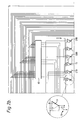
- the ejection seat (not shown) comprises three sets of sensors, 5A, 5B, 5C each set comprising seven sensors 5, with each sensor in each set performing the same function as a corresponding sensor in each of the other two sets so that each sensor is triplicated.
- Each set of sensors may include a pressure sensor for barometric pressure, serving as an altimeter, a temperature sensor, further pressure sensors associated with respective pitots for sensing air speed and sensors for sensing acceleration or deceleration along each of three mutually perpendicular axes, and a temperature sensor for software temperature compensation of pressure sensors and accelerometers.
- Each sensor is connected with respective amplifying, etc.
- each circuit 10 providing a respective analogue output to a respective input of a multiplexer 14, having an output connected to a respective circuit 15 comprising, in combination, an analogue to digital converter and a sample and hold device.
- Each circuit 15 provides, for example on a 16-way parallel input bus 17, an input to a respective 16 bit central processor unit 20 having a non-volatile program memory 22, RAM 24, timers 26, a serial input/output facility 28 and a parallel input/output facility 30.
- Each microprocessor so constituted repeatedly monitors the outputs from the respective set of sensors and, in accordance with the program stored in the respective non-volatile memory 22 and the respective inputs applied thereto via the serial and parallel ports 28, 30, makes decisions as to whether and when particular steps in the operational sequence of the ejection seat should be initiated, such decisions being embodied in coded commands carried on 9-way outputs from the parallel ports to circuitry indicated at 50, each of said outputs being represented by a respective line 32 in Figure 1.
- the circuitry 50 is arranged, in effect, to implement commands from the three microprocessors only when at least two out of these three commands correspond. Thus, the circuitry 50 effectively polls the microprocessors and operates the ejection seat mechanisms in accordance with the result of the poll.
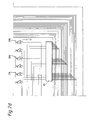
- the circuitry of Figure 2 comprises four blocks 60 of decoding circuits, each block comprising three micro-circuits, each micro-circuit having a respective set of input terminals, each set being connected with respective conductors of a respective one of the three output buses 32 from the microprocessor output ports.
- Each circuit 60 in accordance with the "polling" rationale noted above, is arranged to supply signals to respective sets of output devices which in turn are capable of providing electrical initiation of the respective squibs referenced S1 to S9 in Figure 2.
- the squibs, or the initiators therefor are each duplicated, for the sake of reliability, so that in "normal" operation of the apparatus if, for example, all three microprocessors agree on an action to be initiated, which involves the firing of the squib referenced S2A, not only will that squib be fired but also the squib S2B duplicated therewith.
- Each squib S1 to S9 is arranged, in known manner, to be fired by passing electrical current therethrough from one terminal thereof to another.
- One such terminal (not shown) of each squib is connected to earth whilst the other terminal of each squib is connected to the source of a respective FET 70 having its drain connected to the source of a respective further FET 70 having its drain connected to a supply rail 65 so that each squib is connected, in series with a respective pair of FETs 70, between the power supply rail and earth.
- separate power supplies 67A and 67B are provided for the squibs with suffix A and for the squibs with suffix B.
- Each FET 70 has its gate connected to the output of a respective buffer amplifier 71 having its input connected to a respective output of a decoder device 60.
- the buffers of the respective pair of FETs connected with any of the squibs S1A, S2A, ... S1B, S2B have their inputs connected to respective outputs of different decoder devices 60.
- each microprocessor may include subroutines adapted to compensate for inaccuracies or drift in the sensor outputs with changing physical conditions, such as temperature, pressure, acceleration along particular axes and so on.
- the pressure sensors may be of the solid-state semiconductor type, which are markedly temperature dependent, and the microprocessors may be arranged effectively to apply corrections to signals from the pressure sensors in accordance with signals from the temperature sensors, utilising a look-up table in memory, in a manner known per se.
Landscapes
- Engineering & Computer Science (AREA)
- Physics & Mathematics (AREA)
- General Physics & Mathematics (AREA)
- Automation & Control Theory (AREA)
- Aviation & Aerospace Engineering (AREA)
- Emergency Management (AREA)
- Business, Economics & Management (AREA)
- Air Bags (AREA)
- Nozzles (AREA)
- Spray Control Apparatus (AREA)
- General Preparation And Processing Of Foods (AREA)
- Catching Or Destruction (AREA)
- Combined Controls Of Internal Combustion Engines (AREA)
Applications Claiming Priority (2)
| Application Number | Priority Date | Filing Date | Title |
|---|---|---|---|
| GB9022095 | 1990-10-11 | ||
| GB9022095 | 1990-10-11 |
Publications (3)
| Publication Number | Publication Date |
|---|---|
| EP0480733A2 true EP0480733A2 (de) | 1992-04-15 |
| EP0480733A3 EP0480733A3 (en) | 1992-07-22 |
| EP0480733B1 EP0480733B1 (de) | 1995-05-10 |
Family
ID=10683547
Family Applications (1)
| Application Number | Title | Priority Date | Filing Date |
|---|---|---|---|
| EP91309342A Expired - Lifetime EP0480733B1 (de) | 1990-10-11 | 1991-10-10 | Folgesteuerungsanlage für einen Schleudersitz |
Country Status (4)
| Country | Link |
|---|---|
| US (1) | US5222695A (de) |
| EP (1) | EP0480733B1 (de) |
| AT (1) | ATE122306T1 (de) |
| DE (1) | DE69109608T2 (de) |
Cited By (4)
| Publication number | Priority date | Publication date | Assignee | Title |
|---|---|---|---|---|
| EP0785130A1 (de) * | 1996-01-17 | 1997-07-23 | van den Broek, Eric | Auslösevorrichtung für einen Fallschirm |
| EP3738881A1 (de) * | 2019-05-17 | 2020-11-18 | AMI Industries, Inc. | Universeller sequenzer und kabelbaumanordnung für ausstosssysteme |
| CN112208774A (zh) * | 2020-10-15 | 2021-01-12 | 航宇救生装备有限公司 | 一种双模双余度应急弹射救生电子式开伞器 |
| EP3822168A1 (de) * | 2019-11-16 | 2021-05-19 | AMI Industries, Inc. | Robuste sequenziersysteme für schleudervorrichtung |
Families Citing this family (16)
| Publication number | Priority date | Publication date | Assignee | Title |
|---|---|---|---|---|
| US5881974A (en) * | 1997-02-07 | 1999-03-16 | Larsen & Brusgaard Aps | Method for resetting a timer and a timer especially for use in connection with an item descending from a flying object |
| US6547026B2 (en) * | 1997-10-14 | 2003-04-15 | Deka Products Limited Partnership | Safety separation system |
| EP1006048A3 (de) * | 1998-12-01 | 2001-08-29 | Autoflug GmbH & Co | Verfahren zur Rettung von Personen aus Luftnot mittels eines Schleudersitzes |
| CZ12438U1 (cs) | 2002-05-14 | 2002-07-15 | Jan Lukavec | Zařízení pro automatické otevření padáku |
| US8974137B2 (en) | 2011-12-22 | 2015-03-10 | Caterpillar Inc. | Quick coupler |
| US9217235B2 (en) | 2012-05-30 | 2015-12-22 | Caterpillar Inc. | Tool coupler system having multiple pressure sources |
| US8684623B2 (en) | 2012-05-30 | 2014-04-01 | Caterpillar Inc. | Tool coupler having anti-release mechanism |
| US8869437B2 (en) | 2012-05-30 | 2014-10-28 | Caterpillar Inc. | Quick coupler |
| US9228314B2 (en) | 2013-05-08 | 2016-01-05 | Caterpillar Inc. | Quick coupler hydraulic control system |
| US10384788B2 (en) | 2016-04-18 | 2019-08-20 | Goodrich Corporation | Multiple aircraft seat ejection mode selector |
| CN110687850B (zh) * | 2019-10-30 | 2025-03-18 | 航宇救生装备有限公司 | 控制救生伞可靠开伞及在线检测的小型化电路 |
| CN110824961B (zh) * | 2019-10-31 | 2022-06-17 | 航宇救生装备有限公司 | 一种弹射救生系统主控装置的多路数据源选择的方法 |
| US11390390B2 (en) * | 2020-09-28 | 2022-07-19 | Ami Industries, Inc. | Ejection seat sequence start systems and methods |
| US11548649B2 (en) * | 2020-12-17 | 2023-01-10 | Ami Industries, Inc. | Aircraft escape system and ejection seat sequencer for ejection systems |
| US11834185B2 (en) * | 2022-02-04 | 2023-12-05 | Rockwell Collins, Inc. | Ejection seat parachute deployment systems and methods |
| US20260021894A1 (en) * | 2024-07-17 | 2026-01-22 | Rockwell Collins, Inc. | Ejection seat sequencer time critical delay distribution methods and system |
Family Cites Families (9)
| Publication number | Priority date | Publication date | Assignee | Title |
|---|---|---|---|---|
| US4057206A (en) * | 1975-06-16 | 1977-11-08 | Stencel Aero Engineering Corporation | Ejection sequencing system with airspeed and altitude sensing |
| DE3366887D1 (en) * | 1982-02-09 | 1986-11-20 | Eng Patents & Equip | Vehicle ejection seat system, in particular aircraft ejection seat system |
| US4580746A (en) * | 1983-05-31 | 1986-04-08 | Stencel Aero Engineering Corporation | Capsule and rocket extraction system |
| US4527758A (en) * | 1983-09-12 | 1985-07-09 | The United States Of America As Represented By The Secretary Of The Navy | Deployment sequence mode selection system for aircraft ejection seat |
| US4673147A (en) * | 1985-02-21 | 1987-06-16 | Rockwell International Corporation | Programmable ejection seat system |
| EP0354276A1 (de) * | 1988-08-08 | 1990-02-14 | UNIVERSAL PROPULSION COMPANY, Inc. | Mikroprozessor zur Ablaufsteuerung nach dem Herausschleudern |
| US4792903A (en) * | 1985-07-22 | 1988-12-20 | Universal Propulsion Company, Inc. | Microprocessor controlled post ejection sequencer |
| US4846421A (en) * | 1986-06-23 | 1989-07-11 | The Boeing Company | Adaptive control system for crew escape devices |
| US4721273A (en) * | 1986-08-08 | 1988-01-26 | The Boeing Company | Life-threat assessment and control command for aircrew escape systems |
-
1991
- 1991-10-10 AT AT91309342T patent/ATE122306T1/de not_active IP Right Cessation
- 1991-10-10 EP EP91309342A patent/EP0480733B1/de not_active Expired - Lifetime
- 1991-10-10 US US07/775,693 patent/US5222695A/en not_active Expired - Fee Related
- 1991-10-10 DE DE69109608T patent/DE69109608T2/de not_active Expired - Fee Related
Cited By (6)
| Publication number | Priority date | Publication date | Assignee | Title |
|---|---|---|---|---|
| EP0785130A1 (de) * | 1996-01-17 | 1997-07-23 | van den Broek, Eric | Auslösevorrichtung für einen Fallschirm |
| EP3738881A1 (de) * | 2019-05-17 | 2020-11-18 | AMI Industries, Inc. | Universeller sequenzer und kabelbaumanordnung für ausstosssysteme |
| US12077304B2 (en) | 2019-05-17 | 2024-09-03 | Ami Industries, Inc. | Universal sequencer and wire harness assembly for ejection systems |
| EP3822168A1 (de) * | 2019-11-16 | 2021-05-19 | AMI Industries, Inc. | Robuste sequenziersysteme für schleudervorrichtung |
| US11390389B2 (en) | 2019-11-16 | 2022-07-19 | Ami Industries, Inc. | Robust sequencer systems for ejection assembly |
| CN112208774A (zh) * | 2020-10-15 | 2021-01-12 | 航宇救生装备有限公司 | 一种双模双余度应急弹射救生电子式开伞器 |
Also Published As
| Publication number | Publication date |
|---|---|
| ATE122306T1 (de) | 1995-05-15 |
| US5222695A (en) | 1993-06-29 |
| EP0480733A3 (en) | 1992-07-22 |
| EP0480733B1 (de) | 1995-05-10 |
| DE69109608D1 (de) | 1995-06-14 |
| DE69109608T2 (de) | 1995-09-07 |
Similar Documents
| Publication | Publication Date | Title |
|---|---|---|
| US5222695A (en) | Ejection seat sequencer | |
| US5620203A (en) | Apparatus and method for tripping a safety system for the protection of an occupant of a vehicle | |
| EP2381322B1 (de) | Redundantes Aktuatorsteuersystem | |
| EP2014898A2 (de) | Verteiltes Motorsteuerungssystem | |
| JP6802374B2 (ja) | 車両制御装置および車両制御システム | |
| WO1984000071A1 (en) | Autopilot flight director system | |
| GB2340978A (en) | Smart airbag system | |
| GB2045968A (en) | Transfer system for multi-variable control units | |
| WO1989011986A1 (en) | Apparatus and method for tripping a safety system for the protection of an occupant of a vehicle | |
| JP2011504772A (ja) | 航空機酸素系統制御デバイスの試験方法 | |
| KR100499168B1 (ko) | 계산유닛의기능체크방법 | |
| DE19904367B4 (de) | Zündungssteuerverfahren bei einer passiven Sicherheitsvorrichtung für ein Fahrzeug | |
| EP2507097A2 (de) | Elektronischer mehrkanal-beschleunigungsschalter | |
| US4742515A (en) | Data acquistion and control system | |
| EP1682387B1 (de) | Steuergerät und beschleunigungssensorik | |
| JPH05262190A (ja) | 自動車の総合制御装置 | |
| EP3623228B1 (de) | Fahrzeugsicherheitssystem und verfahren zur steuerung eines fahrzeugsicherheitssystems | |
| EP2110284A1 (de) | Insassenschutzkontrollvorrichtung und Insassenschutzsystem | |
| US8412482B2 (en) | Multi channel electronic acceleration switch | |
| CN214409607U (zh) | 一种基于控制与测量独立的分布式运载火箭控制系统 | |
| CN109353528B (zh) | 一种基于冲击安全判别方法实现的冲击探测传感器 | |
| CN101137965A (zh) | 用于测试控制设备装置的系统和方法 | |
| WO1997015474A3 (de) | Airbagsystem | |
| JPS6388930A (ja) | 通信制御機構 | |
| US4045662A (en) | Self testing monitoring apparatus for multiplexed digital input signals |
Legal Events
| Date | Code | Title | Description |
|---|---|---|---|
| PUAI | Public reference made under article 153(3) epc to a published international application that has entered the european phase |
Free format text: ORIGINAL CODE: 0009012 |
|
| AK | Designated contracting states |
Kind code of ref document: A2 Designated state(s): AT BE CH DE DK ES FR GB GR IT LI LU NL SE |
|
| PUAL | Search report despatched |
Free format text: ORIGINAL CODE: 0009013 |
|
| AK | Designated contracting states |
Kind code of ref document: A3 Designated state(s): AT BE CH DE DK ES FR GB GR IT LI LU NL SE |
|
| 17P | Request for examination filed |
Effective date: 19921123 |
|
| 17Q | First examination report despatched |
Effective date: 19940308 |
|
| GRAA | (expected) grant |
Free format text: ORIGINAL CODE: 0009210 |
|
| AK | Designated contracting states |
Kind code of ref document: B1 Designated state(s): AT BE CH DE DK ES FR GB GR IT LI LU NL SE |
|
| PG25 | Lapsed in a contracting state [announced via postgrant information from national office to epo] |
Ref country code: IT Free format text: LAPSE BECAUSE OF FAILURE TO SUBMIT A TRANSLATION OF THE DESCRIPTION OR TO PAY THE FEE WITHIN THE PRE;WARNING: LAPSES OF ITALIAN PATENTS WITH EFFECTIVE DATE BEFORE 2007 MAY HAVE OCCURRED AT ANY TIME BEFORE 2007. THE CORRECT EFFECTIVE DATE MAY BE DIFFERENT FROM THE ONE RECORDED.SCRIBED TIME-LIMIT Effective date: 19950510 Ref country code: BE Effective date: 19950510 Ref country code: ES Free format text: THE PATENT HAS BEEN ANNULLED BY A DECISION OF A NATIONAL AUTHORITY Effective date: 19950510 Ref country code: DK Effective date: 19950510 Ref country code: NL Free format text: LAPSE BECAUSE OF NON-PAYMENT OF DUE FEES Effective date: 19950510 Ref country code: LI Effective date: 19950510 Ref country code: CH Effective date: 19950510 Ref country code: GR Free format text: LAPSE BECAUSE OF FAILURE TO SUBMIT A TRANSLATION OF THE DESCRIPTION OR TO PAY THE FEE WITHIN THE PRESCRIBED TIME-LIMIT Effective date: 19950510 Ref country code: AT Effective date: 19950510 |
|
| REF | Corresponds to: |
Ref document number: 122306 Country of ref document: AT Date of ref document: 19950515 Kind code of ref document: T |
|
| REF | Corresponds to: |
Ref document number: 69109608 Country of ref document: DE Date of ref document: 19950614 |
|
| PG25 | Lapsed in a contracting state [announced via postgrant information from national office to epo] |
Ref country code: SE Effective date: 19950810 |
|
| ET | Fr: translation filed | ||
| REG | Reference to a national code |
Ref country code: CH Ref legal event code: PL |
|
| PG25 | Lapsed in a contracting state [announced via postgrant information from national office to epo] |
Ref country code: LU Free format text: LAPSE BECAUSE OF NON-PAYMENT OF DUE FEES Effective date: 19951031 |
|
| NLV1 | Nl: lapsed or annulled due to failure to fulfill the requirements of art. 29p and 29m of the patents act | ||
| PLBE | No opposition filed within time limit |
Free format text: ORIGINAL CODE: 0009261 |
|
| STAA | Information on the status of an ep patent application or granted ep patent |
Free format text: STATUS: NO OPPOSITION FILED WITHIN TIME LIMIT |
|
| 26N | No opposition filed | ||
| REG | Reference to a national code |
Ref country code: GB Ref legal event code: IF02 |
|
| PGFP | Annual fee paid to national office [announced via postgrant information from national office to epo] |
Ref country code: DE Payment date: 20081014 Year of fee payment: 18 |
|
| PGFP | Annual fee paid to national office [announced via postgrant information from national office to epo] |
Ref country code: FR Payment date: 20081014 Year of fee payment: 18 |
|
| REG | Reference to a national code |
Ref country code: FR Ref legal event code: ST Effective date: 20100630 |
|
| PG25 | Lapsed in a contracting state [announced via postgrant information from national office to epo] |
Ref country code: FR Free format text: LAPSE BECAUSE OF NON-PAYMENT OF DUE FEES Effective date: 20091102 Ref country code: DE Free format text: LAPSE BECAUSE OF NON-PAYMENT OF DUE FEES Effective date: 20100501 |
|
| PGFP | Annual fee paid to national office [announced via postgrant information from national office to epo] |
Ref country code: GB Payment date: 20101006 Year of fee payment: 20 |
|
| REG | Reference to a national code |
Ref country code: GB Ref legal event code: PE20 Expiry date: 20111009 |
|
| PG25 | Lapsed in a contracting state [announced via postgrant information from national office to epo] |
Ref country code: GB Free format text: LAPSE BECAUSE OF EXPIRATION OF PROTECTION Effective date: 20111009 |