EP0480740B1 - Tamper indicating closure having deflectable portion in top wall - Google Patents
Tamper indicating closure having deflectable portion in top wall Download PDFInfo
- Publication number
- EP0480740B1 EP0480740B1 EP91309359A EP91309359A EP0480740B1 EP 0480740 B1 EP0480740 B1 EP 0480740B1 EP 91309359 A EP91309359 A EP 91309359A EP 91309359 A EP91309359 A EP 91309359A EP 0480740 B1 EP0480740 B1 EP 0480740B1
- Authority
- EP
- European Patent Office
- Prior art keywords
- end panel
- button
- closure cap
- panel
- panel according
- Prior art date
- Legal status (The legal status is an assumption and is not a legal conclusion. Google has not performed a legal analysis and makes no representation as to the accuracy of the status listed.)
- Expired - Lifetime
Links
- 230000009471 action Effects 0.000 abstract description 2
- 238000010276 construction Methods 0.000 description 8
- 238000007789 sealing Methods 0.000 description 7
- UAOUIVVJBYDFKD-XKCDOFEDSA-N (1R,9R,10S,11R,12R,15S,18S,21R)-10,11,21-trihydroxy-8,8-dimethyl-14-methylidene-4-(prop-2-enylamino)-20-oxa-5-thia-3-azahexacyclo[9.7.2.112,15.01,9.02,6.012,18]henicosa-2(6),3-dien-13-one Chemical compound C([C@@H]1[C@@H](O)[C@@]23C(C1=C)=O)C[C@H]2[C@]12C(N=C(NCC=C)S4)=C4CC(C)(C)[C@H]1[C@H](O)[C@]3(O)OC2 UAOUIVVJBYDFKD-XKCDOFEDSA-N 0.000 description 5
- 230000002093 peripheral effect Effects 0.000 description 5
- 230000008859 change Effects 0.000 description 3
- 239000000463 material Substances 0.000 description 3
- 230000015572 biosynthetic process Effects 0.000 description 2
- 230000000994 depressogenic effect Effects 0.000 description 2
- 238000001514 detection method Methods 0.000 description 2
- 238000004146 energy storage Methods 0.000 description 2
- 230000000007 visual effect Effects 0.000 description 2
- 229910000831 Steel Inorganic materials 0.000 description 1
- 235000008452 baby food Nutrition 0.000 description 1
- 239000011248 coating agent Substances 0.000 description 1
- 238000000576 coating method Methods 0.000 description 1
- 150000001875 compounds Chemical class 0.000 description 1
- 230000000694 effects Effects 0.000 description 1
- 235000013305 food Nutrition 0.000 description 1
- 239000011521 glass Substances 0.000 description 1
- 230000002427 irreversible effect Effects 0.000 description 1
- 238000004519 manufacturing process Methods 0.000 description 1
- 239000002184 metal Substances 0.000 description 1
- 230000004048 modification Effects 0.000 description 1
- 238000012986 modification Methods 0.000 description 1
- 238000003908 quality control method Methods 0.000 description 1
- 239000010959 steel Substances 0.000 description 1
- 238000009461 vacuum packaging Methods 0.000 description 1
Images



Classifications
-
- B—PERFORMING OPERATIONS; TRANSPORTING
- B65—CONVEYING; PACKING; STORING; HANDLING THIN OR FILAMENTARY MATERIAL
- B65D—CONTAINERS FOR STORAGE OR TRANSPORT OF ARTICLES OR MATERIALS, e.g. BAGS, BARRELS, BOTTLES, BOXES, CANS, CARTONS, CRATES, DRUMS, JARS, TANKS, HOPPERS, FORWARDING CONTAINERS; ACCESSORIES, CLOSURES, OR FITTINGS THEREFOR; PACKAGING ELEMENTS; PACKAGES
- B65D79/00—Kinds or details of packages, not otherwise provided for
- B65D79/005—Packages having deformable parts for indicating or neutralizing internal pressure-variations by other means than venting
- B65D79/0087—Packages having deformable parts for indicating or neutralizing internal pressure-variations by other means than venting the deformable part being located in a closure, e.g. in caps or lids
Definitions
- This invention relates in general to new and useful improvements in closures having built in tamper indicating means in the form of deflectable buttons or panel areas which deform depending upon the particular condition of closing of a container by such closure caps. Most particularly, this invention relates to a change in the structural shape of a closure button or panel area so as to enhance the energy stored therein and to greatly increase the same.
- Vacuum indicating buttons on closures are used extensively for the food industry because they are an effective quick-detection means that lets one know some very important conditions about the container. For example: Is the container sealed? - button is in “down” position; has the container been opened, or tampered? - button is in “up” position; has the seal been broken because of other causes, such as: severe handling, slow leakage or cracked glass at the seal area that could result in product spoilage. It is also very reasurring to hear the button "pop" as the closure is twisted off of the container. In addition, the button is an invaluable quality control means at the product filling operation.
- the position of the button and the "pop" noise made thereby when a container is opened have not been the only usage. More recently, it has been proposed to utilize the movement of the button or other panel area of a closure to provide for a permanent indication of container opening. For example, it has been proposed to provide a frangible or brittle type coating that can be irreversibly fractured by the movement of a panel portion (button) that may, for example, provide a color change to indicate that a container is either presently opened or has been previously opened and reclosed.
- Fig. 1 is a top plan view of a conventional PRIOR ART closure cap having an end panel with a button formation therein.
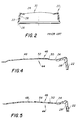
- Fig. 2 is a further prior art showing in the form of a vertical sectional view of the closure cap of Fig. 1 taken generally along the line 2-2 of Fig. 1.
- Fig. 3 is a plan view of a modified form of button type closure cap with high energy storage utilizing a number of corners or facets in accordance with the invention.
- Fig. 4 is a fragmentary enlarged vertical sectional view taken generally along the line 4-4 of Fig. 3.
- Fig. 5 is another fragmentary enlarged vertical sectional view through the closure cap of Fig. 3, but taken along the line 5-5 of Fig. 3.
- Fig. 6 is a transverse vertical sectional view similar to Fig. 4 but wherein the panel configuration is inverted from that of Fig. 4 and is mechanically actuated.
- Fig. 7 is an enlarged fragmentary vertical sectional view similar to Fig. 5 of the inverted panel configuration.
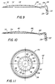
- Fig. 8 is a top plan view of another type of closure wherein the energy storage construction is formed in a separate panel which is suitably bonded to a central part of an end panel of the closure cap.
- Fig. 9 is an enlarged fragmentary vertical sectional view taken generally along the line 9-9 of Fig. 8 and shows the separate mounting of the panel and the panel configuration area.
- Fig. 10 is an enlarged fragmentary vertical sectional view similar to Fig. 9 and taken generally along the line 10-10 of Fig. 8 and shows a faceted cross section.
- Fig. 11 is a top plan view of a modified form of closure cap showing a different type of faceted energy enhancement arrangement.
- Fig. 12 is an enlarged fragmentary vertical sectional view taken generally along the line 12-12 of Fig. 11 and shows the arrangements of the different facets in a button type arrangement.
- Fig. 13 is an enlarged fragmentary transverse vertical sectional view similar to Fig. 12 but shows the faceted arrangement in an inverted position.
- Fig 14 is another enlarged fragmentary vertical sectional view similar to Fig. 12 and shows a facet arrangement wherein the facets are straight as opposed to tapered.
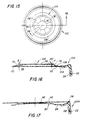
- Fig. 15 is a top plan view of a closure cap wherein the faceted panel arrangement is formed separate from the closure cap end panel.
- Fig. 16 is an enlarged fragmentary transverse vertical sectional view taken generally along the line 16-16 of Fig. 15 and shows more specifically the construction of the panel.
- Fig. 17 is a transverse vertical sectional view taken through a conventional button type closure cap wherein the closure cap is provided with indicia for permanently indicating removal of the closure cap even if the closure cap is returned.
- closure cap 20 which is generally illustrated by the numeral 20.
- the closure cap 20 is preferably formed of metal and includes a generally cylindrical skirt 22 depending from an end panel 24.
- the skirt 22 terminates in an inwardly directed curl 26 and is lined by a sealing compound 28 which also underlies the outer periphery of the end panel 24.
- the illustrated closure cap 20 is intended to be pressed on to a container having a threaded neck finish with the sealing compound 28 forming threads to facilitate the removal of the closure cap 20.
- the closure cap 20 is primarily intended to be utilized in conjunction with a container which is to be vacuum filled.
- the end panel 24 includes a central button generally identified by the numeral 30.
- the button 30, as is best shown in Fig. 1, includes a central circular part 32, an intermediate annular part 34 and an outer sloping part 36.
- the button 30 in the initially manufacutred state of the closure cap 20, the button 30 is upwardly directed.
- a closure cap such as the closure cap 20 has been in use for a period of years. However, it provides only visual evidence that a vacuum exists within an associated container.
- the closure cap 20A is of the same general construction as to the closure cap 20 and includes an end panel 24 and a depending skirt 22 with there being a sealing compound 28 for forming both a threaded connnection and a top seal with a container neck finish. Further, the end panel 24 is provided with a central button 30.
- the closure cap 20A differs from the closure cap 20 in that there is an upstanding peripheral rib 38 at the junction between the end panel 24 and the skirt 22.
- the button 30 carries a layer of brittle or frangible material 40 which underlies a panel 42 which extends within and is generally seated on the rib 38.
- the brittle material 40 is carried by the button 30 although it may be carried by the panel 42.
- the operation of the closure cap 28 is that when the button 30 is drawn down by a vacuum, and the vacuum is released, such as may occur when the closure cap is removed from a vacuum packed container, the button 30, due to stored energy therein, snaps upwardly and operates to fracture the brittle material 40. This results in permanent evidence that the closure cap 20A has been removed from a container even if the closure cap 20A is again placed on the container under vacuum conditions.
- closure caps similar to the arrangement of the closure cap 20A wherein an equivalent button 30 is normally in a depressed position and is mechanically forced upwardly when the closure cap is applied.
- This invention most particuarly relates to a modification of the general button area of a closure cap so as to increase the flip energy of such closure cap.
- closure cap 20 which is typically used for the Baby Food Industry
- buttons noise of a conventional commercial type button typically ranges from 124-128 dba whereas in accordance with this invention, button noise may be increased to typically range from 137-139 dba.
- Figs. 3-5 wherein there is illustrated a modified closure cap, formed in accordance with this invention, which is generally identified by the numeral 44.
- the closure cap 44 is of a similar construction to the closure cap 20 and includes an end panel 24, a depending skirt 22 and a terminal curl 28.
- the skirt 22 and the peripheral portion of the end panel 24 are lined with a sealing compound 28.
- the closure cap 44 differs from the closure cap 20 in the configuration of a central button or panel area 46.
- the button or panel area 46 includes a circular central uppermost part 48 and is outlined by a generally sloping outer annular part 50. In the illustrated embodiment of the button or panel area 46, there are four radially extending parts 52 which present the same cross section as in the case of the button 30. These are shown in Fig. 4.
- the above described button or panel area 46 may be identified as being of the "propeller” type with the illustrated embodiment being a four "propeller” type. Different numbers of faceted areas 54 are feasible although it has been found that the four facet panel type is most feasible from a manufacturing standpoint.
- closure cap 44 is of the vacuum actuated type
- the principles of the closure cap 44 may be utilized in a closure cap wherein the button or panel area is mechanically actuated.
- a closure cap generally identified by the numeral 56
- the closure cap 56 will have a peripheral construction corresponding to that of the closure caps 20 and 44 but will have an end panel 58 of a modified construction.
- the closure cap 56 will have a depressed button or panel area generally identified by the numeral 60.
- the button or panel area 60 will be of the same outline and cross section as the button or panel area 46 except that it will be inverted. Accordingly, like numerals will be applied to the various areas of the button or panel areas 60 as applied to the button or panel area 46.
- the button or panel area 60 will, however, be mechanically actuated by suitable mechanical means.
- suitable mechanical means One known type of mechanical actuator is to provide a plurality of depending buttons or actuators 62 about the periphery of the end panel 58 for engagement with the end finish (not shown) of a container.
- the button 62 When the closure cap 56 is applied to a container, the button 62 will be flattened which will cause the button or panel area 60 to snap upwardly.
- the button or panel area 60 will return to its original position.
- closure cap 56 has been illustrated as having a sealing compound for forming a threaded interlock with a container neck finish, it is pointed out here that it may be desirable that the skirt 22 be formed with shaped threads so that the closure cap 56, instead of being pressed on to a container, will be threaded on to such a container.
- closure cap 64 employing the "propeller" type of button or panel area, this closure cap being generally identified by the numeral 64.
- the closure cap 64 will incorporate a separately formed button or panel area generally identified by the numeral 66 which will be of the same configuration as the button or panel area 46.
- the closure cap 66 will be formed with an end panel 68 which is generally flat at least in the central portion thereof.
- the separately formed button or panel portion 66 will be seated on the end panel 68 and peripherally bonded thereto as at 70 to effect a flexing of the end panel 68.
- button or panel area 66 will be of the same configuration as the button or panel area 46, the same reference numeral will be utilized and no further description of the specific configuration thereof is believed to be necessary.
- inverted button or panel area 66 is also feasible to form the inverted button or panel area 66 as separate and apart from the end panel in the same manner as shown in Figs. 8-10.
- FIG. 11 wherein there is illustrated yet another form of closure cap which incorporates the high energy benefits of a faceted arrangement.
- the closure cap of Fig. 11 is generally identified by the numeral 72 and, like the closure cap 20, includes a depending skirt 22, which surrounds the end panel 24 and which skirt 22 terminates in a lower curl 26. Further, the skirt 22 and a peripheral part of the end panel 24 is provided with a lining of suitable sealing compound 28.
- the closure cap 72 differs from the closure caps 20 and 44 in the formation of a central button or panel area generally identified by the numeral 74.
- the button or panel area 74 like the button or panel area 46, for example, includes a central post 76 and an outer narrow annular tilted flange 78. Between the post 76 and the flange 78, the button or panel area 74 is of a faceted construction. This faceted construction includes two sets of facets, facets 80 and facets 82 which are arranged in circumferentially alternating relation.
- each of the facets 80, 82 are in the form of a flat area and that the slope of the facets 80 is at an angle A with respect to the plane of the post 76 while the slope of the facets 82 is at an angle B to the plane of the post 76.
- Angles A and B are different and angle A may be on the order of 4° while angle B is on the order of 5°.
- buttons or panel area 74 has eight facets, the number of facets can vary. Further, the angles of the facets may also be varied depending upon the results desired.
- closure cap 72 illustrated in Figs. 11 and 12 is intended to be utilized with a vacuum packed arrangement.
- a multi faceted button or panel area may be utilized in conjunction with a mechanical actuator.
- FIG. 13 With respect thereto, reference is made to Fig. 13 and the modified closure cap 84 illustrated therein.
- the closure cap 84 will have an end panel 86 with the central portion thereof being in the form of a recessed button or panel area generally identified by the numeral 88.
- the button or panel area 88 will be of the same outline and cross section as that of the button or panel area 74 except that it will be inverted from that shown in Fig. 12.
- the outer periphery of the end panel 78 will be provided with a plurality of circumferentially arranged and depending mechanical acutators 90 in the form of buttons which will engage the end sealing surface of a container so as to cause the button or panel area 88 to flip upwardly when the closure cap 84 is applied.
- connection between the closure cap 84 and a container neck finish so as to make it of a screw threaded type as opposed to being of a push-on self thread forming type.
- the closure cap 92 has a modified form of end panel 94 which includes a slightly modified form of button or panel area generally identified by the numeral 96.
- the button or panel area 96 will have the same general outline as that of the button or panel area 74, but in lieu of the faceted areas sloping, the button or panel area 96 will include a set of relatively shallow facets 98 which are circumferentially alternated with a set of deeper faceted areas 100, the planes of the faceted areas 98, 100 being substantially parallel to that of the post 76.
- button or panel area 96 as illustrated in Fig. 14 is intended to be vacuum actuated, it is to be understood that it may be inverted in the manner generally shown in Fig. 13 so as to be mechanically actuated.
- the closure cap 102 will include a basic cap like that shown in Figs. 9 and 10 including an end panel 104 with an integral skirt 22 etc.
- the central part of the end panel 104 will carry a separately formed button or panel portion generally identified by the numeral 106 and having the same outline as the button or panel portion 74 of Fig. 11.
- the button or panel portion 106 will include a peripheral part 108 which will be suitably bonded to the end panel 104 as at 110.
- buttons or panel portion 106 which are identical to those of the button or panel portion 74 will be identified by like reference numerals.
- closure caps correesponding generally to the closure cap 102 of Figs. 15 and 16 and having separately formed button or panel areas but incorporating the features of the closure caps 84 and 92 of Figs. 13 and 14 may be utilized.
- closure cap arrangements of Figs. 3-16 may be incorporated in closure cap arrangements having irreversible tamper indicating arrangements such as that broadly disclosed in Fig. 17.
Landscapes
- Mechanical Engineering (AREA)
- Engineering & Computer Science (AREA)
- Closures For Containers (AREA)
- Cartons (AREA)
- Glass Compositions (AREA)
- Polymerisation Methods In General (AREA)
- Slot Machines And Peripheral Devices (AREA)
- Air Bags (AREA)
- Input Circuits Of Receivers And Coupling Of Receivers And Audio Equipment (AREA)
- Residential Or Office Buildings (AREA)
- Load-Bearing And Curtain Walls (AREA)
- Push-Button Switches (AREA)
- Floor Finish (AREA)
Applications Claiming Priority (2)
| Application Number | Priority Date | Filing Date | Title |
|---|---|---|---|
| US07/597,879 US5119962A (en) | 1990-10-12 | 1990-10-12 | Closure button/panel energy enhancement |
| US597879 | 1990-10-12 |
Publications (2)
| Publication Number | Publication Date |
|---|---|
| EP0480740A1 EP0480740A1 (en) | 1992-04-15 |
| EP0480740B1 true EP0480740B1 (en) | 1995-01-18 |
Family
ID=24393288
Family Applications (1)
| Application Number | Title | Priority Date | Filing Date |
|---|---|---|---|
| EP91309359A Expired - Lifetime EP0480740B1 (en) | 1990-10-12 | 1991-10-10 | Tamper indicating closure having deflectable portion in top wall |
Country Status (15)
| Country | Link |
|---|---|
| US (1) | US5119962A (da) |
| EP (1) | EP0480740B1 (da) |
| JP (1) | JP3431640B2 (da) |
| KR (1) | KR100206401B1 (da) |
| AT (1) | ATE117263T1 (da) |
| AU (1) | AU639651B2 (da) |
| BR (1) | BR9104424A (da) |
| CA (1) | CA2052751C (da) |
| CR (1) | CR4625A (da) |
| DE (1) | DE69106831T2 (da) |
| DK (1) | DK0480740T3 (da) |
| ES (1) | ES2069828T3 (da) |
| MX (1) | MX9101553A (da) |
| MY (1) | MY107652A (da) |
| ZA (1) | ZA918125B (da) |
Families Citing this family (8)
| Publication number | Priority date | Publication date | Assignee | Title |
|---|---|---|---|---|
| US5839603A (en) * | 1996-09-11 | 1998-11-24 | Erie County Plastics Corporation | Lightweight peel-top can lid |
| JPH1129161A (ja) * | 1997-07-11 | 1999-02-02 | Aokiko Kenkyusho:Kk | 延伸ブロー成形による広口瓶の密閉構造 |
| EP1236653A1 (en) * | 2001-02-22 | 2002-09-04 | N.V. Nutricia | Tamper evident closure |
| US6786348B2 (en) * | 2001-05-24 | 2004-09-07 | Crown Cork & Seal Technologies Corporation | Gasket for press-on twist-off closure |
| ES2485965T3 (es) | 2006-12-20 | 2014-08-14 | Fábricas Monterrey, S.A. De C.V. | Método para indicar presión en una bebida embotellada usando una tapa metálica tipo corona |
| US8893906B2 (en) | 2013-03-15 | 2014-11-25 | Silgan White Cap LLC | Metal closure and seal combination for maintaining the shape of a plastic container neck |
| CN107849168B (zh) | 2015-07-31 | 2020-07-14 | 埃克森美孚化学专利公司 | 从烯烃聚合方法中回收未反应的单体 |
| RU2019137481A (ru) * | 2017-04-21 | 2021-05-21 | КЕН ФОРМИНГ ТЕКНОЛОДЖИС, ЭлЭлСи | Профиль свода контейнера облегченной конструкции и способ его изготовления |
Family Cites Families (12)
| Publication number | Priority date | Publication date | Assignee | Title |
|---|---|---|---|---|
| US933347A (en) * | 1908-01-23 | 1909-09-07 | Frank G Turner | Jar cap or closure. |
| GB610342A (en) * | 1946-01-30 | 1948-10-14 | Gen Electric Co Ltd | Improvements in or relating to hermetically sealed containers |
| US3062396A (en) * | 1960-07-07 | 1962-11-06 | Anchor Hocking Glass Corp | Closure cap and method of making same |
| US3160302A (en) * | 1960-11-03 | 1964-12-08 | Continental Can Co | Conainer closure |
| US4533059A (en) * | 1984-06-13 | 1985-08-06 | Continental White Cap, Inc. | Vacuum-tamper indicating button for smaller diameter caps and the like |
| US4552279A (en) * | 1984-09-14 | 1985-11-12 | Owens-Illinois, Inc. | Container closure |
| US4616761A (en) * | 1984-11-19 | 1986-10-14 | Owens-Illinois, Inc. | Vacuum indicating thermoplastic closure |
| US4603786A (en) * | 1985-04-02 | 1986-08-05 | Continental White Cap, Inc. | Press-on closure for resealable glass finish |
| US4678082A (en) * | 1986-07-10 | 1987-07-07 | Owens-Illinois, Inc. | Vacuum indicating thermoplastic closure |
| US4721219A (en) * | 1986-11-17 | 1988-01-26 | Owens-Illinois Closure Inc. | Composite, vacuum indicating closure |
| US4957211A (en) * | 1989-07-11 | 1990-09-18 | American National Can Company | Vacuum-indicating closure |
| US5016769A (en) * | 1990-07-09 | 1991-05-21 | Continental White Cap, Inc. | Closure with high energy button |
-
1990
- 1990-10-12 US US07/597,879 patent/US5119962A/en not_active Expired - Lifetime
-
1991
- 1991-10-03 CA CA002052751A patent/CA2052751C/en not_active Expired - Lifetime
- 1991-10-08 AU AU85646/91A patent/AU639651B2/en not_active Expired
- 1991-10-10 EP EP91309359A patent/EP0480740B1/en not_active Expired - Lifetime
- 1991-10-10 DE DE69106831T patent/DE69106831T2/de not_active Expired - Lifetime
- 1991-10-10 AT AT91309359T patent/ATE117263T1/de not_active IP Right Cessation
- 1991-10-10 ES ES91309359T patent/ES2069828T3/es not_active Expired - Lifetime
- 1991-10-10 DK DK91309359.7T patent/DK0480740T3/da active
- 1991-10-11 KR KR1019910017929A patent/KR100206401B1/ko not_active Expired - Lifetime
- 1991-10-11 MY MYPI91001858A patent/MY107652A/en unknown
- 1991-10-11 BR BR919104424A patent/BR9104424A/pt not_active IP Right Cessation
- 1991-10-11 ZA ZA918125A patent/ZA918125B/xx unknown
- 1991-10-11 MX MX9101553A patent/MX9101553A/es not_active IP Right Cessation
- 1991-10-11 JP JP26398091A patent/JP3431640B2/ja not_active Expired - Fee Related
-
1992
- 1992-02-13 CR CR4625A patent/CR4625A/es not_active Application Discontinuation
Also Published As
| Publication number | Publication date |
|---|---|
| BR9104424A (pt) | 1992-06-09 |
| JPH04253651A (ja) | 1992-09-09 |
| ES2069828T3 (es) | 1995-05-16 |
| ATE117263T1 (de) | 1995-02-15 |
| MY107652A (en) | 1996-05-30 |
| EP0480740A1 (en) | 1992-04-15 |
| DE69106831T2 (de) | 1995-06-29 |
| ZA918125B (en) | 1992-06-24 |
| AU639651B2 (en) | 1993-07-29 |
| MX9101553A (es) | 1992-06-05 |
| AU8564691A (en) | 1992-04-16 |
| US5119962A (en) | 1992-06-09 |
| CR4625A (es) | 1993-10-08 |
| DE69106831D1 (de) | 1995-03-02 |
| CA2052751A1 (en) | 1992-04-13 |
| CA2052751C (en) | 2003-04-01 |
| KR100206401B1 (ko) | 1999-07-01 |
| JP3431640B2 (ja) | 2003-07-28 |
| DK0480740T3 (da) | 1995-06-12 |
Similar Documents
| Publication | Publication Date | Title |
|---|---|---|
| US4938370A (en) | Tamper-indicating plastic closure | |
| CA2303881C (en) | Tamper indicating closure with foldable tab | |
| US4978017A (en) | Tamper-indicating plastic closure | |
| US5031787A (en) | Low height floating disk closure | |
| JP3382964B2 (ja) | 不正表示プラスチック閉鎖体 | |
| EP0871585B1 (en) | Plastic lug closure | |
| EP1470054B1 (en) | Composite closure having disk tightening feature | |
| US6039218A (en) | Tamper-evident closure with abutment | |
| US4436212A (en) | Tamper proof closure | |
| US4530437A (en) | Tamperproof package | |
| US4957211A (en) | Vacuum-indicating closure | |
| GB2198715A (en) | Tamper-indicating band for a screw-threaded cap | |
| EP0381118B1 (en) | Tamper-indicating plastic closure | |
| US4533059A (en) | Vacuum-tamper indicating button for smaller diameter caps and the like | |
| EP0480740B1 (en) | Tamper indicating closure having deflectable portion in top wall | |
| US5022545A (en) | Tamper evident closure | |
| US6068151A (en) | Tamper-indicating plastic closure having pilfer band | |
| US4519516A (en) | Tamper indicating package | |
| US3519159A (en) | Closure cap with rip-tab release and cam-off means | |
| US5833087A (en) | Button-type tamper indicating metal closure | |
| RU2845879C1 (ru) | Укупорочное устройство для ёмкости | |
| GB2186272A (en) | Closure device | |
| EA050854B1 (ru) | Укупорочное устройство для ёмкости | |
| CA1185924A (en) | Tamper proof closure | |
| JPH0375422B2 (da) |
Legal Events
| Date | Code | Title | Description |
|---|---|---|---|
| PUAI | Public reference made under article 153(3) epc to a published international application that has entered the european phase |
Free format text: ORIGINAL CODE: 0009012 |
|
| AK | Designated contracting states |
Kind code of ref document: A1 Designated state(s): AT BE CH DE DK ES FR GB GR IT LI LU NL SE |
|
| 17P | Request for examination filed |
Effective date: 19921010 |
|
| 17Q | First examination report despatched |
Effective date: 19940317 |
|
| GRAA | (expected) grant |
Free format text: ORIGINAL CODE: 0009210 |
|
| AK | Designated contracting states |
Kind code of ref document: B1 Designated state(s): AT BE CH DE DK ES FR GB GR IT LI LU NL SE |
|
| PG25 | Lapsed in a contracting state [announced via postgrant information from national office to epo] |
Ref country code: GR Free format text: LAPSE BECAUSE OF FAILURE TO SUBMIT A TRANSLATION OF THE DESCRIPTION OR TO PAY THE FEE WITHIN THE PRESCRIBED TIME-LIMIT Effective date: 19950118 |
|
| REF | Corresponds to: |
Ref document number: 117263 Country of ref document: AT Date of ref document: 19950215 Kind code of ref document: T |
|
| REF | Corresponds to: |
Ref document number: 69106831 Country of ref document: DE Date of ref document: 19950302 |
|
| ITF | It: translation for a ep patent filed | ||
| PG25 | Lapsed in a contracting state [announced via postgrant information from national office to epo] |
Ref country code: SE Effective date: 19950418 |
|
| ET | Fr: translation filed | ||
| REG | Reference to a national code |
Ref country code: ES Ref legal event code: FG2A Ref document number: 2069828 Country of ref document: ES Kind code of ref document: T3 |
|
| REG | Reference to a national code |
Ref country code: DK Ref legal event code: T3 |
|
| PLBE | No opposition filed within time limit |
Free format text: ORIGINAL CODE: 0009261 |
|
| STAA | Information on the status of an ep patent application or granted ep patent |
Free format text: STATUS: NO OPPOSITION FILED WITHIN TIME LIMIT |
|
| 26N | No opposition filed | ||
| REG | Reference to a national code |
Ref country code: GB Ref legal event code: IF02 |
|
| PGFP | Annual fee paid to national office [announced via postgrant information from national office to epo] |
Ref country code: AT Payment date: 20090921 Year of fee payment: 19 Ref country code: DK Payment date: 20091026 Year of fee payment: 19 Ref country code: CH Payment date: 20091026 Year of fee payment: 19 Ref country code: LU Payment date: 20091102 Year of fee payment: 19 Ref country code: DE Payment date: 20091028 Year of fee payment: 19 Ref country code: ES Payment date: 20091026 Year of fee payment: 19 |
|
| PGFP | Annual fee paid to national office [announced via postgrant information from national office to epo] |
Ref country code: NL Payment date: 20091024 Year of fee payment: 19 |
|
| PGFP | Annual fee paid to national office [announced via postgrant information from national office to epo] |
Ref country code: IT Payment date: 20091028 Year of fee payment: 19 Ref country code: GB Payment date: 20091026 Year of fee payment: 19 Ref country code: FR Payment date: 20091029 Year of fee payment: 19 |
|
| PGFP | Annual fee paid to national office [announced via postgrant information from national office to epo] |
Ref country code: BE Payment date: 20091201 Year of fee payment: 19 |
|
| BERE | Be: lapsed |
Owner name: *CONTINENTAL WHITE CAP INC. Effective date: 20101031 |
|
| REG | Reference to a national code |
Ref country code: NL Ref legal event code: V1 Effective date: 20110501 |
|
| REG | Reference to a national code |
Ref country code: DK Ref legal event code: EBP |
|
| REG | Reference to a national code |
Ref country code: CH Ref legal event code: PL |
|
| GBPC | Gb: european patent ceased through non-payment of renewal fee |
Effective date: 20101010 |
|
| PG25 | Lapsed in a contracting state [announced via postgrant information from national office to epo] |
Ref country code: FR Free format text: LAPSE BECAUSE OF NON-PAYMENT OF DUE FEES Effective date: 20101102 Ref country code: CH Free format text: LAPSE BECAUSE OF NON-PAYMENT OF DUE FEES Effective date: 20101031 Ref country code: LI Free format text: LAPSE BECAUSE OF NON-PAYMENT OF DUE FEES Effective date: 20101031 |
|
| REG | Reference to a national code |
Ref country code: FR Ref legal event code: ST Effective date: 20110630 |
|
| PG25 | Lapsed in a contracting state [announced via postgrant information from national office to epo] |
Ref country code: NL Free format text: LAPSE BECAUSE OF NON-PAYMENT OF DUE FEES Effective date: 20110501 Ref country code: AT Free format text: LAPSE BECAUSE OF NON-PAYMENT OF DUE FEES Effective date: 20101010 Ref country code: BE Free format text: LAPSE BECAUSE OF NON-PAYMENT OF DUE FEES Effective date: 20101031 Ref country code: GB Free format text: LAPSE BECAUSE OF NON-PAYMENT OF DUE FEES Effective date: 20101010 |
|
| REG | Reference to a national code |
Ref country code: DE Ref legal event code: R119 Ref document number: 69106831 Country of ref document: DE Effective date: 20110502 |
|
| PG25 | Lapsed in a contracting state [announced via postgrant information from national office to epo] |
Ref country code: DK Free format text: LAPSE BECAUSE OF NON-PAYMENT OF DUE FEES Effective date: 20101031 |
|
| REG | Reference to a national code |
Ref country code: ES Ref legal event code: FD2A Effective date: 20111118 |
|
| PG25 | Lapsed in a contracting state [announced via postgrant information from national office to epo] |
Ref country code: IT Free format text: LAPSE BECAUSE OF NON-PAYMENT OF DUE FEES Effective date: 20101010 |
|
| PG25 | Lapsed in a contracting state [announced via postgrant information from national office to epo] |
Ref country code: ES Free format text: LAPSE BECAUSE OF NON-PAYMENT OF DUE FEES Effective date: 20101011 |
|
| PG25 | Lapsed in a contracting state [announced via postgrant information from national office to epo] |
Ref country code: LU Free format text: LAPSE BECAUSE OF NON-PAYMENT OF DUE FEES Effective date: 20101010 |
|
| PG25 | Lapsed in a contracting state [announced via postgrant information from national office to epo] |
Ref country code: DE Free format text: LAPSE BECAUSE OF NON-PAYMENT OF DUE FEES Effective date: 20110502 |