EP0480904A2 - Système incrémentiel de mesure de longueur - Google Patents
Système incrémentiel de mesure de longueur Download PDFInfo
- Publication number
- EP0480904A2 EP0480904A2 EP91890210A EP91890210A EP0480904A2 EP 0480904 A2 EP0480904 A2 EP 0480904A2 EP 91890210 A EP91890210 A EP 91890210A EP 91890210 A EP91890210 A EP 91890210A EP 0480904 A2 EP0480904 A2 EP 0480904A2
- Authority
- EP
- European Patent Office
- Prior art keywords
- housing
- measuring system
- protective housing
- reference mark
- scale
- Prior art date
- Legal status (The legal status is an assumption and is not a legal conclusion. Google has not performed a legal analysis and makes no representation as to the accuracy of the status listed.)
- Granted
Links
Images


Classifications
-
- G—PHYSICS
- G01—MEASURING; TESTING
- G01D—MEASURING NOT SPECIALLY ADAPTED FOR A SPECIFIC VARIABLE; ARRANGEMENTS FOR MEASURING TWO OR MORE VARIABLES NOT COVERED IN A SINGLE OTHER SUBCLASS; TARIFF METERING APPARATUS; MEASURING OR TESTING NOT OTHERWISE PROVIDED FOR
- G01D5/00—Mechanical means for transferring the output of a sensing member; Means for converting the output of a sensing member to another variable where the form or nature of the sensing member does not constrain the means for converting; Transducers not specially adapted for a specific variable
- G01D5/12—Mechanical means for transferring the output of a sensing member; Means for converting the output of a sensing member to another variable where the form or nature of the sensing member does not constrain the means for converting; Transducers not specially adapted for a specific variable using electric or magnetic means
- G01D5/244—Mechanical means for transferring the output of a sensing member; Means for converting the output of a sensing member to another variable where the form or nature of the sensing member does not constrain the means for converting; Transducers not specially adapted for a specific variable using electric or magnetic means influencing characteristics of pulses or pulse trains; generating pulses or pulse trains
- G01D5/245—Mechanical means for transferring the output of a sensing member; Means for converting the output of a sensing member to another variable where the form or nature of the sensing member does not constrain the means for converting; Transducers not specially adapted for a specific variable using electric or magnetic means influencing characteristics of pulses or pulse trains; generating pulses or pulse trains using a variable number of pulses in a train
- G01D5/2454—Encoders incorporating incremental and absolute signals
- G01D5/2455—Encoders incorporating incremental and absolute signals with incremental and absolute tracks on the same encoder
- G01D5/2457—Incremental encoders having reference marks
-
- H—ELECTRICITY
- H03—ELECTRONIC CIRCUITRY
- H03M—CODING; DECODING; CODE CONVERSION IN GENERAL
- H03M1/00—Analogue/digital conversion; Digital/analogue conversion
- H03M1/12—Analogue/digital converters
- H03M1/22—Analogue/digital converters pattern-reading type
- H03M1/24—Analogue/digital converters pattern-reading type using relatively movable reader and disc or strip
- H03M1/28—Analogue/digital converters pattern-reading type using relatively movable reader and disc or strip with non-weighted coding
- H03M1/30—Analogue/digital converters pattern-reading type using relatively movable reader and disc or strip with non-weighted coding incremental
- H03M1/308—Analogue/digital converters pattern-reading type using relatively movable reader and disc or strip with non-weighted coding incremental with additional pattern means for determining the absolute position, e.g. reference marks
Definitions
- the invention relates to an incremental length measuring system, with a scale having a measuring graduation, a scanning unit with scanning elements for generating measuring signals when scanning the measuring graduation and an evaluation unit for these measuring signals, wherein a reference track parallel to the measuring graduation with several reference marks corresponding to a reference point, assigned scanning elements Provided in the scanning unit and a selection switch that can be actuated by an assignment magnet that can be attached in association with a reference mark in a protective housing for the scale and the scanning unit and that can be adjusted with the scanning unit and that generates or emits a reference pulse only at at least one reference mark selected via the permanent magnet allows.
- a selection option for reference marks is provided in order to simplify the manufacture of the measuring systems and, as far as possible, without the need for external intervention in the encapsulation of the measuring system, to select a specific, e.g. B. to enable the machine zero point of a machine tool corresponding reference point and thus to be able to relate the measurements to the machine zero point.
- a selection of reference marks also makes sense in other cases if measurements related to them are to be carried out. From DE-OS 18 14 785 mechanical on-off switches are known which are actuated via stops when adjusting the scanning unit and which activate the evaluation circuit only at preselected reference marks.
- the main object of the invention is to create a length measuring system of the type mentioned, in which a selection of any reference marks is made possible with simple means and without intervention in the interior of the protective housing and the selection made can be changed if necessary.
- a partial object of the invention is to provide a length measuring system in which longitudinal displacements of the scale body in the region of the selected reference mark are prevented even if the selected reference mark is not exactly in the center of the scale.
- the main task is solved in that a permanent magnet is permanently assigned to each selectable reference mark in the protective housing and can be adjusted via actuators from an inactive position with respect to the selection switch to an active position.
- Simple devices can be used for the adjustment of the permanent magnets from the active to the inactive and vice versa. Since a permanent magnet is assigned to every selectable reference mark, no modifications or lengthy assembly work on the length measuring system are required.
- each permanent magnet is adjustably attached with a support which can be rotated or pivoted in the housing from a position which rejects the movement path of the selection switch into a position which activates the switch when it is moved past.
- the selection switch is mounted in an external driver for the scanning unit and the permanent magnets are mounted with their carriers in a receiving bore or groove provided in the longitudinal direction next to this driver in the protective housing and are adjustable from the outside of the housing.
- the permanent magnets are accommodated in the protective housing on supports that can be adjusted via external actuators.
- These permanent magnets can be seated on flaps with foot parts in longitudinal grooves of the housing, which is usually formed from an extruded aluminum profile, can be pivoted through closable housing openings and can be locked in the pivoting end positions.
- An embodiment variant which enables simple construction and easy assembly of the permanent magnets, is characterized in that as a carrier for the permanent magnets, at least over the length of the mounting area of the selectable reference marks on the scale, but preferably over the entire length of the scale, is made of elastic, in particular rubber-elastic Deformable material is provided, which engages with a foot part at an edge in the clamping seat in a holding groove inside the tubular protective housing and carries the permanent magnets assigned to the individual reference marks at a distance from the foot part outside the activation area for the switch, with a closable housing opening in the area of each reference mark is provided, by means of which the band can be bent in this area around the foot part by inserted screws or press-in bodies, so that the associated permanent magnet is adjusted in the activation area for the switch.
- an elastically deformable band held on both edges in grooves in the protective housing which is concavely curved in the inactive position with respect to the housing interior and which, in the area of an activated magnet, assumes a concave curvature by being pushed in by means of the screw or the press-in body.
- the housing is additionally sealed against the housing openings for the screws or press-in bodies by a tape attached in this way.
- the actuators and / or carriers for the permanent magnets in their position holding the permanent magnet in the activation position at the same time the in the housing in a groove to compensate for different thermal expansions of the housing, scale or the object equipped with the length measuring system to the required extent, by means of flexible holders that are held longitudinally adjustable in the area of the selected reference mark, in particular clamp.
- the protective housing forming a carrier can preferably be fixed immovably in the longitudinal direction on the object with one or more holding elements in the area of the selected reference mark, so that the selected reference mark coincides with the fixed point of the protective housing and therefore normally also with the machine zero point.
- the overall construction described can also be used if no permanent magnets are used to select a reference mark.
- these permanent magnets are replaced by the same actuators, with the help of which the scale can be clamped.
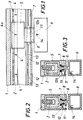
- a scanning unit 5 is adjustable, which was only illustrated in its outline and has known lighting and reception devices for optoelectronic scanning of the measuring graduation 3 and the reference marks 4, with the aid of which scanning signals converting measuring graduation 3 into count signals and 4 reference pulses can be generated by scanning the reference marks.
- the scanning unit 5 sits on a sword-like support 6 and is guided with this between sealing lips 7 through a slit-shaped housing opening 8 to the outside, where it is coupled to a driver 9, from which a cable 10 also shown in FIG. 8 to an evaluation or Display unit leads to the display of the measurement result.
- the length measuring system is known in principle.
- each carrier 12 or 12a is equipped with a permanent magnet 13 which, only in its activation position, is capable of activating a relay or another switch 14 attached in the driver 9.
- Each carrier 12 is assigned to a reference mark 4, so that a reference pulse generated at the assigned reference mark 4a during the scanning is used in the measuring system only when the switch 14 is activated.
- each reference mark on the scale body 2 is assigned a flap-like carrier 17, which is held by a base part 15 in a molded-in housing groove 16 and carries a permanent magnet 18.
- each selectable reference mark and thus each flap 17 is assigned an opening which can be closed by a stopper 19.
- the flap 17 is adjusted from the position shown in FIG. 5 to the position shown in FIG. 4 with the aid of a suitable tool, the flap 17 being secured in the position shown in FIG 4 position can be made. Furthermore, the flap is secured by a larger plug 21.
- a permanent magnet 18 in the position according to FIG. 4 activates the switch 14 when the scanning unit 5 moves past in the sense of an evaluation of the reference pulse generated at the assigned reference mark.
- the scale body 2 is fixed with its longitudinal edge in a groove 22 of the protective housing 1 so that it can be displaced longitudinally to a limited extent, for which purpose an elastically flexible holder 23 is provided which fills the groove 22 around the edge of the scale body 2.
- This bracket can be made of an elastomer, e.g. B. silicone rubber exist. But it is also possible to cross the longitudinal direction or use diagonally corrugated spring bodies.
- the scanning unit 5 is again provided with a selection switch 24.
- Each selectable reference mark is assigned a carrier body 26 with a permanent magnet 27, which is chamfered on one side in its basic shape, in a groove 25 that is open in the shape of a segment of a circle in cross section and is open toward the groove 22, and is illustrated in FIG. 6 in its inactive position. Openings are provided in the ceiling of the housing by means of plugs 28, via which the body 26, like the body 12 according to FIGS. 2 and 3, can be rotated so that the permanent magnet 27 enters an activation area for the switch 24.
- the body 26 originally aligned with its chamfer with the groove wall moves into the groove 22 from the side and thereby clamps the scale body 2 in the region of the selected reference mark on the housing 1 due to the narrowing of the groove 22 while compressing the element 23 firmly.
- the closable by the plug 28 openings can be formed as threaded openings, so that in the area of the selected reference mark, a holding element 29 for the scale housing 1 can be fastened with the aid of screws 31 penetrating its foot part 30 and engaging in the openings released by the plugs 28.
- Through elongated holes 32 of the element 29 fastening screws for fixing the measuring system can be attached to a machine.
- a longitudinal slot 33 is connected to the openings forming thread openings in the central area against the scale ends.
- Holding elements 34 provided here for the housing 1 carry 35 lower parts 36 on their lower flange, the shape of which is adapted to the coherent cross-section of slot 33 and groove 25, so that they can be moved longitudinally and to the extent necessary a longitudinal adjustment of the housing relative to the fastening points of these fastening elements 34 on the object.
- the ends of the housing 1 can be closed by cover 37.
Landscapes
- Engineering & Computer Science (AREA)
- Theoretical Computer Science (AREA)
- Physics & Mathematics (AREA)
- General Physics & Mathematics (AREA)
- Transmission And Conversion Of Sensor Element Output (AREA)
- Length Measuring Devices With Unspecified Measuring Means (AREA)
- Measurement Of Length, Angles, Or The Like Using Electric Or Magnetic Means (AREA)
- A Measuring Device Byusing Mechanical Method (AREA)
Applications Claiming Priority (2)
| Application Number | Priority Date | Filing Date | Title |
|---|---|---|---|
| AT0204490A AT394446B (de) | 1990-10-11 | 1990-10-11 | Inkrementales laengenmesssystem |
| AT2044/90 | 1990-10-11 |
Publications (3)
| Publication Number | Publication Date |
|---|---|
| EP0480904A2 true EP0480904A2 (fr) | 1992-04-15 |
| EP0480904A3 EP0480904A3 (fr) | 1992-05-13 |
| EP0480904B1 EP0480904B1 (fr) | 1994-04-06 |
Family
ID=3526566
Family Applications (1)
| Application Number | Title | Priority Date | Filing Date |
|---|---|---|---|
| EP91890210A Expired - Lifetime EP0480904B1 (fr) | 1990-10-11 | 1991-09-16 | Système incrémentiel de mesure de longueur |
Country Status (4)
| Country | Link |
|---|---|
| US (1) | US5115573A (fr) |
| EP (1) | EP0480904B1 (fr) |
| AT (1) | AT394446B (fr) |
| DE (1) | DE59101322D1 (fr) |
Cited By (1)
| Publication number | Priority date | Publication date | Assignee | Title |
|---|---|---|---|---|
| DE4244178A1 (de) * | 1992-12-24 | 1994-07-07 | Heidenhain Gmbh Dr Johannes | Längen- oder Winkelmeßeinrichtung |
Families Citing this family (26)
| Publication number | Priority date | Publication date | Assignee | Title |
|---|---|---|---|---|
| US5344610A (en) * | 1993-02-03 | 1994-09-06 | Eastman Kodak Company | Aspirator probe with long pivot arm to minimize tip flick |
| US5273717A (en) * | 1992-09-30 | 1993-12-28 | Eastman Kodak Company | Self-calibrating analyzer aspirator |
| AT397309B (de) * | 1992-11-02 | 1994-03-25 | Rsf Elektronik Gmbh | Messwagen für ein lineares messsystem |
| EP0662603B1 (fr) * | 1993-12-08 | 1997-03-12 | Dr. Johannes Heidenhain GmbH | Système de mesure de longueurs |
| EP0668486A3 (fr) * | 1994-02-22 | 1997-07-30 | Heidenhain Gmbh Dr Johannes | Dispositif de mesure d'angles ou de longueurs. |
| DE4406797C2 (de) * | 1994-03-02 | 1997-11-27 | Heidenhain Gmbh Dr Johannes | Positionsmeßeinrichtung |
| DE4406799C2 (de) * | 1994-03-02 | 1997-11-06 | Heidenhain Gmbh Dr Johannes | Positionsmeßeinrichtung |
| DE4406798C2 (de) * | 1994-03-02 | 1997-11-27 | Heidenhain Gmbh Dr Johannes | Positionsmeßeinrichtung |
| ATE161327T1 (de) * | 1994-05-06 | 1998-01-15 | Heidenhain Gmbh Dr Johannes | Temperatur-kompensierte positionsmesseinrichtung |
| DE4428590C2 (de) * | 1994-08-12 | 1996-06-20 | Heidenhain Gmbh Dr Johannes | Positionsmeßeinrichtung |
| US5837981A (en) * | 1997-07-24 | 1998-11-17 | Wang; Chin-Yuan | Signal outputting device of optical ruler |
| JP3668111B2 (ja) * | 2000-09-06 | 2005-07-06 | 株式会社ミツトヨ | ユニット型リニアスケール |
| US20020133964A1 (en) * | 2001-02-13 | 2002-09-26 | Asm Automation Sensorik Messtechnik Gmbh | Magnetic length measuring device |
| DE10117193B4 (de) * | 2001-04-05 | 2013-04-04 | Anton Rodi | Messsystem zur Absolutwerterfassung von Winkeln oder Wegen |
| US6912797B2 (en) * | 2001-04-05 | 2005-07-05 | Anton Rodi | Measuring system for recording absolute angular or position values |
| US6922907B2 (en) | 2001-04-05 | 2005-08-02 | Anton Rodi | Measuring system for recording absolute angular or position values |
| JP2004301541A (ja) * | 2003-03-28 | 2004-10-28 | Mitsutoyo Corp | 長さ測定装置の弾性固定具及び固定方法 |
| US6910279B1 (en) | 2004-05-12 | 2005-06-28 | Dr. Johannes Heidenhain Gmbh | Holder for a graduated element |
| GB0415141D0 (en) * | 2004-07-06 | 2004-08-11 | Renishaw Plc | Scale reading apparatus |
| DE102005055513B4 (de) * | 2005-11-18 | 2021-05-06 | Dr. Johannes Heidenhain Gmbh | Vorrichtung mit einem Trägerkörper und einem Maßstab |
| DE102006015725A1 (de) * | 2006-04-04 | 2007-10-11 | Dr. Johannes Heidenhain Gmbh | Verfahren zum Initialisieren eines Positionsmesssystems |
| DE102011079464A1 (de) * | 2011-07-20 | 2013-01-24 | Dr. Johannes Heidenhain Gmbh | Längenmesseinrichtung |
| JP5972658B2 (ja) * | 2012-05-11 | 2016-08-17 | Dmg森精機株式会社 | スケール装置 |
| CN107238362B (zh) * | 2017-07-03 | 2023-06-27 | 中国电建集团贵阳勘测设计研究院有限公司 | 一种位移传感器立式智能检验仪及检测方法 |
| ES2943517T3 (es) * | 2020-04-08 | 2023-06-13 | Heidenhain Gmbh Dr Johannes | Disposición para medición de posición |
| CN112756859B (zh) * | 2020-12-30 | 2023-03-21 | 中核北方核燃料元件有限公司 | 一种端塞与包壳管管内焊缝间隙确认方法 |
Family Cites Families (18)
| Publication number | Priority date | Publication date | Assignee | Title |
|---|---|---|---|---|
| DE1814785A1 (de) * | 1968-12-14 | 1970-06-25 | Johannes Heidenhain Feinmechan | Zaehlanordnung |
| US3982106A (en) * | 1973-05-14 | 1976-09-21 | Contraves Ag | System for measuring the longitudinal or angular displacement of a movable component |
| DE2540412C3 (de) * | 1975-09-11 | 1987-01-22 | Dr. Johannes Heidenhain Gmbh, 8225 Traunreut | Inkrementales Meßsystem |
| US4013944A (en) * | 1976-01-02 | 1977-03-22 | The United States Of America As Represented By The Secretary Of The Navy | Pressure insensitive system for measuring the length of a cable deployed underwater using magnet actuated reed switches |
| DE2948854A1 (de) * | 1979-12-05 | 1981-06-11 | Dr. Johannes Heidenhain Gmbh, 8225 Traunreut | Inkrementales messsystem |
| DE3037810C2 (de) * | 1980-10-07 | 1982-11-04 | Dr. Johannes Heidenhain Gmbh, 8225 Traunreut | Inkrementale Längen- oder Winkelmeßeinrichtung |
| DE3144334C2 (de) * | 1981-11-07 | 1985-06-13 | Dr. Johannes Heidenhain Gmbh, 8225 Traunreut | Wegmeßeinrichtung mit Referenzmarken |
| DE3204012C1 (de) * | 1982-02-05 | 1983-02-03 | Dr. Johannes Heidenhain Gmbh, 8225 Traunreut | Inkrementale Messeinrichtung |
| DE3245357C2 (de) * | 1982-12-08 | 1985-02-14 | Dr. Johannes Heidenhain Gmbh, 8225 Traunreut | Inkrementale Meßeinrichtung |
| DE3245914C1 (de) * | 1982-12-11 | 1984-03-29 | Dr. Johannes Heidenhain Gmbh, 8225 Traunreut | Messeinrichtung |
| DE3337653A1 (de) * | 1983-10-17 | 1985-05-02 | Dr. Johannes Heidenhain Gmbh, 8225 Traunreut | Verfahren zur signaluebertragung und einrichtung zur durchfuehrung des verfahrens |
| DE3562948D1 (en) * | 1984-04-21 | 1988-06-30 | Heidenhain Gmbh Dr Johannes | Position-measuring device |
| DE3644979A1 (de) * | 1986-12-24 | 1988-07-07 | Pav Praezisions Apparatebau Ag | Messkluppe |
| DE8634637U1 (de) * | 1986-12-24 | 1989-08-31 | PAV Präzisions-Apparatebau AG, Vaduz | Meßkluppe |
| DE3707190A1 (de) * | 1987-03-06 | 1988-09-22 | Pav Praezisions Apparatebau Ag | Messkluppe |
| AT390674B (de) * | 1989-02-07 | 1990-06-11 | Rsf Elektronik Gmbh | Inkrementales messsystem |
| AT395071B (de) * | 1989-02-09 | 1992-09-10 | Rieder & Schwaiger Sentop | Inkrementales messsystem |
| DE3914739A1 (de) * | 1989-05-05 | 1990-11-08 | Heidenhain Gmbh Dr Johannes | Inkrementale positionsmesseinrichtung mit referenzmarken |
-
1990
- 1990-10-11 AT AT0204490A patent/AT394446B/de not_active IP Right Cessation
-
1991
- 1991-09-16 DE DE91890210T patent/DE59101322D1/de not_active Expired - Fee Related
- 1991-09-16 EP EP91890210A patent/EP0480904B1/fr not_active Expired - Lifetime
- 1991-09-26 US US07/766,813 patent/US5115573A/en not_active Expired - Lifetime
Cited By (1)
| Publication number | Priority date | Publication date | Assignee | Title |
|---|---|---|---|---|
| DE4244178A1 (de) * | 1992-12-24 | 1994-07-07 | Heidenhain Gmbh Dr Johannes | Längen- oder Winkelmeßeinrichtung |
Also Published As
| Publication number | Publication date |
|---|---|
| US5115573A (en) | 1992-05-26 |
| EP0480904A3 (fr) | 1992-05-13 |
| ATA204490A (de) | 1991-09-15 |
| DE59101322D1 (de) | 1994-05-11 |
| EP0480904B1 (fr) | 1994-04-06 |
| AT394446B (de) | 1992-03-25 |
Similar Documents
| Publication | Publication Date | Title |
|---|---|---|
| EP0480904B1 (fr) | Système incrémentiel de mesure de longueur | |
| DE69715840T2 (de) | Befestigungselement und damit befestigtes ligament | |
| DE3223469C2 (de) | Einstelleinrichtung für Kopfhörer | |
| EP0177693A2 (fr) | Potentiomètre | |
| EP1463922A1 (fr) | Element detecteur magnetostrictif | |
| EP0158050B1 (fr) | Dispositif de mesure capsulé | |
| WO2000058693A1 (fr) | Dispositif de detection | |
| DE4228305C2 (de) | Führungsschelle für mindestens eine flexible Leitung | |
| DE3120267C2 (de) | Stromschienensystem mit elektrische Betriebsmittel tragenden aufsetzbaren Adaptern | |
| DE3022440C2 (de) | Mehrteilige Grundplatte für Möbelscharniere | |
| DE10201880B4 (de) | Magnetostriktives Sensor-Element | |
| EP4060226A1 (fr) | Dispositif d'éclairage | |
| DE29821471U1 (de) | Befestigungssystem | |
| DE10154967A1 (de) | Klemmvorrichtung zur Befestigung von Bauelementen an mit einer T-Nut versehenen Halteelementen | |
| AT405000B (de) | Feldabstandhalter für hochspannungs-freileitungen mit bündelleitern | |
| AT395920B (de) | Installationsgeraet, das mittels haken des gehaeuses an sammelschienen einhaengbar ist | |
| EP0769415A1 (fr) | Dispositif de retenue | |
| DE19646575A1 (de) | Vorrichtung zur justierbaren Halterung von Platten, insbesondere von Glasscheiben oder dergleichen | |
| DE10026082C1 (de) | Vorrichtung zur Befestigung eines Sensors an einem Druckmittelzylinder | |
| EP0540955A1 (fr) | Dispositif pour fixer un aimant permanent en forme de barre | |
| AT398352B (de) | Installationsgerät | |
| DE19631941C2 (de) | Befestigung für eine Abdeckung | |
| DE3712824A1 (de) | Stufenlos verstellbare montagevorrichtung | |
| EP0183065B1 (fr) | Lampe de bureau | |
| DE19622175C1 (de) | Halterung für ein Kabelbündel |
Legal Events
| Date | Code | Title | Description |
|---|---|---|---|
| PUAI | Public reference made under article 153(3) epc to a published international application that has entered the european phase |
Free format text: ORIGINAL CODE: 0009012 |
|
| PUAL | Search report despatched |
Free format text: ORIGINAL CODE: 0009013 |
|
| AK | Designated contracting states |
Kind code of ref document: A2 Designated state(s): BE CH DE FR GB IT LI LU NL SE |
|
| AK | Designated contracting states |
Kind code of ref document: A3 Designated state(s): BE CH DE FR GB IT LI LU NL SE |
|
| 17P | Request for examination filed |
Effective date: 19920504 |
|
| 17Q | First examination report despatched |
Effective date: 19930921 |
|
| GRAA | (expected) grant |
Free format text: ORIGINAL CODE: 0009210 |
|
| AK | Designated contracting states |
Kind code of ref document: B1 Designated state(s): BE CH DE FR GB IT LI LU NL SE |
|
| PG25 | Lapsed in a contracting state [announced via postgrant information from national office to epo] |
Ref country code: IT Free format text: LAPSE BECAUSE OF FAILURE TO SUBMIT A TRANSLATION OF THE DESCRIPTION OR TO PAY THE FEE WITHIN THE PRESCRIBED TIME-LIMIT;WARNING: LAPSES OF ITALIAN PATENTS WITH EFFECTIVE DATE BEFORE 2007 MAY HAVE OCCURRED AT ANY TIME BEFORE 2007. THE CORRECT EFFECTIVE DATE MAY BE DIFFERENT FROM THE ONE RECORDED. Effective date: 19940406 Ref country code: GB Effective date: 19940406 Ref country code: FR Effective date: 19940406 Ref country code: BE Effective date: 19940406 Ref country code: NL Effective date: 19940406 Ref country code: SE Free format text: THE PATENT HAS BEEN ANNULLED BY A DECISION OF A NATIONAL AUTHORITY Effective date: 19940406 |
|
| REF | Corresponds to: |
Ref document number: 59101322 Country of ref document: DE Date of ref document: 19940511 |
|
| EN | Fr: translation not filed | ||
| NLV1 | Nl: lapsed or annulled due to failure to fulfill the requirements of art. 29p and 29m of the patents act | ||
| PG25 | Lapsed in a contracting state [announced via postgrant information from national office to epo] |
Ref country code: LI Effective date: 19940930 Ref country code: CH Effective date: 19940930 Ref country code: LU Free format text: LAPSE BECAUSE OF NON-PAYMENT OF DUE FEES Effective date: 19940930 |
|
| GBV | Gb: ep patent (uk) treated as always having been void in accordance with gb section 77(7)/1977 [no translation filed] |
Effective date: 19940406 |
|
| PLBE | No opposition filed within time limit |
Free format text: ORIGINAL CODE: 0009261 |
|
| STAA | Information on the status of an ep patent application or granted ep patent |
Free format text: STATUS: NO OPPOSITION FILED WITHIN TIME LIMIT |
|
| 26N | No opposition filed | ||
| REG | Reference to a national code |
Ref country code: CH Ref legal event code: PL |
|
| PGFP | Annual fee paid to national office [announced via postgrant information from national office to epo] |
Ref country code: DE Payment date: 20070921 Year of fee payment: 17 |
|
| PG25 | Lapsed in a contracting state [announced via postgrant information from national office to epo] |
Ref country code: DE Free format text: LAPSE BECAUSE OF NON-PAYMENT OF DUE FEES Effective date: 20090401 |