EP0480936B1 - Verfahren und vorrichtung zum schützen eines schiffskörpers oder unterwasserbauwerks gegen biologische verschmutzung - Google Patents
Verfahren und vorrichtung zum schützen eines schiffskörpers oder unterwasserbauwerks gegen biologische verschmutzung Download PDFInfo
- Publication number
- EP0480936B1 EP0480936B1 EP90907525A EP90907525A EP0480936B1 EP 0480936 B1 EP0480936 B1 EP 0480936B1 EP 90907525 A EP90907525 A EP 90907525A EP 90907525 A EP90907525 A EP 90907525A EP 0480936 B1 EP0480936 B1 EP 0480936B1
- Authority
- EP
- European Patent Office
- Prior art keywords
- hull
- transducers
- water
- fouling
- generating
- Prior art date
- Legal status (The legal status is an assumption and is not a legal conclusion. Google has not performed a legal analysis and makes no representation as to the accuracy of the status listed.)
- Expired - Lifetime
Links
Images

Classifications
-
- B—PERFORMING OPERATIONS; TRANSPORTING
- B63—SHIPS OR OTHER WATERBORNE VESSELS; RELATED EQUIPMENT
- B63B—SHIPS OR OTHER WATERBORNE VESSELS; EQUIPMENT FOR SHIPPING
- B63B59/00—Hull protection specially adapted for vessels; Cleaning devices specially adapted for vessels
- B63B59/04—Preventing hull fouling
-
- G—PHYSICS
- G10—MUSICAL INSTRUMENTS; ACOUSTICS
- G10K—SOUND-PRODUCING DEVICES; METHODS OR DEVICES FOR PROTECTING AGAINST, OR FOR DAMPING, NOISE OR OTHER ACOUSTIC WAVES IN GENERAL; ACOUSTICS NOT OTHERWISE PROVIDED FOR
- G10K11/00—Methods or devices for transmitting, conducting or directing sound in general; Methods or devices for protecting against, or for damping, noise or other acoustic waves in general
- G10K11/18—Methods or devices for transmitting, conducting or directing sound
- G10K11/26—Sound-focusing or directing, e.g. scanning
- G10K11/34—Sound-focusing or directing, e.g. scanning using electrical steering of transducer arrays, e.g. beam steering
- G10K11/341—Circuits therefor
- G10K11/346—Circuits therefor using phase variation
Definitions
- the present invention relates to a method and a system for counteracting marine, i.e. marine biologic, fouling of a ship's hull or some other construction which is submerged in sea water, and more specifically by using mechanical vibrations.
- marine i.e. marine biologic
- fouling of a ship's hull or some other construction which is submerged in sea water, and more specifically by using mechanical vibrations.
- Norwegian patent no. 82676 is used a system of high frequency sound, i.e. "ultrasound", from transducers mounted on the inside of the hull, so that the hull propagates ultrasonic frequencies (the wave lengths in the hull are then shorter than about 25 cm, and in the water just outside the hull shorter than about 7 cm).
- nodal lines For example bulkhead walls inside the ship's hull will constitute such fixed nodal lines in the locations where the bulkhead walls are welded to the hull, so that the ship's hull will vibrate only between the bulkhead walls. Thus, along such nodal lines the desired water particle movements will be too small to prevent fouling.
- nodal lines nodal lines or points in the usual acoustic sense, wherein nodal points (compare “Kundt's tube”) are points with a periodic location in accordance with the sound wavelength .
- nodal points compact "Kundt's tube”
- lines or points on a ship's hull which are mechanically clamped, i.e. fixed from the inside of the hull by constructional details, usually bulkhead walls, and these lines or points therefore cannot undertake transverse oscillations.
- the present invention aims to eliminate the fouling problem in the nodal line areas, and also aims to provide an efficient combatting of said marine biologic type of fouling.
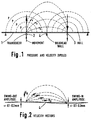
- Fig. 1 appears a section through a ship's hull 1 to be put in oscillation by means of electro-mechanical transducers 2, 3.
- the problem is that the bulkhead wall 4 clamps the hull against transverse oscillations, so that the necessary relative water particle movement between water and hull is not achieved in this area, only in the surrounding areas where said hull is able to oscillate (up and down in the drawing).
- Fig. 3 appears an approximate square wave time behavior for the dynamic pressure in the water, which ensures maximum acceleration.
- a pressure behavior is obtained by applying to the transducers a drive signal of a special type, see the curve shapes in the upper part of Fig. 3.
- a fundamental frequency about 20-30 Hz forms the starting point for generating a number of harmonics, which harmonics are then added to or superposed upon said fundamental frequency.
- the coefficients used in this operation are determined from knowledge regarding particular physical characteristics of said transducers. The resonance frequency and the efficiency are of particular importance. Only odd harmonics are used in the superposing operation.
- Fig. 4 displays at left the ship's hull 1 in section as viewed along the main axis of the ship.
- Six transducers are present, of which three are visible and the other three transducers are hidden right behind the three visible ones.
- the same configuration is viewed from the side, and this drawing illustrates how the water particle velocity also achieves a sufficient value in the area along the nodal line 4 between the transducer pairs, by means of a superposing effect.
- further transducer rows outside the indicated nodal lines in the outer edges of the right part of the drawing which transducer rows cooperate in a corresponding manner with the transducer points shown.
- transducer pairs are excited in inverted phase oscillations, so that "water dipoles” are created therebetween.
- the phenomenon can also be regarded as a so-called “push-pull” configuration, where the water mass simultaneously is pushed in one end and pulled in the other end. This mode of operation ensures the highest possible efficiency and movement coverage of the nodal line areas.
- the water movement should preferably have the same spatial size order as the size of the larvae in question, that is the water particles must move with an amplitude of about +/- 0,1-0,2 mm. In the vibrating areas of the hull, this is achieved by exciting oscillatory hull amplitudes of just such a size order, i.e. +/- 0,1-0,2 mm. In order to achieve the necessary anti-fouling effect in the nodal line areas, it must additionally be taken care that the applied drive voltage to the transducers provide a maximum acceleration in the dipole system, and thereby also the highest possible velocity.
- the special drive voltage applied to the transducers has a time behavior of a quite particular type.
- a Fourier technique is used in which odd harmonics are superposed upon the "key note” oscillation in question, and with scaling coefficients for each particular harmonic, which scaling coefficients are determined from a knowledge of different physical parameters for the transducers in question, like resonance frequency, efficiency and similar parameters.
- inverted phase working transducers are situated in rows on each side of said nodal line, and said transducers are working in pairs against each other in a "push-pull" configuration.
- the effect is of course attenuated in a lateral direction, but due to the superposing from two adjacent pairs of transducers, there is also achieved a good effect sideways along the nodal line.
- transducer rows it is possible to make a row of such transducers cooperate in pairs with transducer rows on each side, i.e. when a transducer row is situated between two parallell nodal lines.
- the transducers in a pair are located in the same distance from the nodal line, the transducers shall normally oscillate in reverse phase with each other. However, if the distances are somewhat different, or other assymetric conditions are present, a certain additional phase change will be of interest for one of the two transducers in the pair. This phase deviation can be obtained by delaying one of the two inverted phase voltages correspondingly, so that optimum particle velocity conditions are always achieved over the nodal line.
- the mechanical vibration system can be used advantageously in combination with a coating system which aims to prevent fouling by other types of organisms.
- these two effects will complete each other and provide a very good anti-fouling effect.
- an anti-fouling layer consisting of a material which has very low surface tension/surface energy in relation to and against water, which lowers the possibility that the organisms in question can get stuck to the hull by adhesion.
- the material is of a type which successively dissolves in sea water, and thereby removes organisms which are about to be deposited on the hull.
- Possible layers for this type of completing effect consist of a material of organic type, preferably comprising therein silicon, fluorine, nitrogen or oxygen, possibly one or more of said substances in combination.
Landscapes
- Engineering & Computer Science (AREA)
- Chemical & Material Sciences (AREA)
- Combustion & Propulsion (AREA)
- Mechanical Engineering (AREA)
- Ocean & Marine Engineering (AREA)
- Acoustics & Sound (AREA)
- Physics & Mathematics (AREA)
- Multimedia (AREA)
- Agricultural Chemicals And Associated Chemicals (AREA)
- Apparatuses For Generation Of Mechanical Vibrations (AREA)
- Catching Or Destruction (AREA)
- Investigation Of Foundation Soil And Reinforcement Of Foundation Soil By Compacting Or Drainage (AREA)
- Processing Of Solid Wastes (AREA)
- Prevention Of Electric Corrosion (AREA)
- Transducers For Ultrasonic Waves (AREA)
Claims (9)
- Verfahren zur Bekämpfung einer maritimen Verschmutzung auf der Außenseite einer Schiffswand (1) oder eines anderen Unterwasserbauwerks, wobei bei dem Verfahren eine Anzahl von elektromechanischen Schwingungswandlern (2, 3) verwendet wird, die auf der Innenseite der Schiffswand (1) montiert sind, wobei die Wandler (2, 3) mechanische niederfrequente Schwingungen an die Wand (1) anlegen, wenn eine elektrische Antriebsenergie an die Wandler angelegt wird, wobei die niederfrequenten Schwingungen für die Bekämpfung der Verschmutzung durch Wasserpartikelbewegungen im wesentlichen senkrecht zur Wand in Bereichen mit ausreichenden Schwingungsamplituden der Wand sorgen, und wobei bei dem Verfahren ein untergeordnetes System elektrische Antriebsspannungen erzeugt und den Wandlern zuleitet,
dadurch gekennzeichnet, daß die Wandler (2, 3), die paarweise in einer Weise angeordnet sind, daß jeder Wandler eines Paars in einer festen oder vorgegebenen Entfernung auf einer entsprechenden Seite einer festen Knotenlinie (4) auf der Wand (1) angeordnet ist, mit Antriebsspannungen beliefert werden, die einen derartigen zeitlichen Verlauf haben, daß ein Partikelgeschwindigkeitsvektorfeld dem Wasser außerhalb der Wand vermittelt wird, das eine parallele Richtung zur Wand unmittelbar außerhalb der Knotenlinie und einen maximalen Zahlenwert im gleichen Bereich hat. - Verfahren nach Anspruch 1, dadurch gekennzeichnet, daß die zwei paarweisen Wandler (2, 3) im wesentlichen in einem invertierten Phasenbetrieb oder in einem abweichenden invertieren Phasenbetrieb angetrieben werden, wobei die Abweichung durch die genaue Lage der Wandler relativ zueinander und zur Knotenlinie (4) bestimmt wird.
- Verfahren nach Anspruch 1 oder 2,
dadurch gekennzeichnet, daß das untergeordnete System Antriebsspannungen für die Wandler erzeugt durchI) Erzeugen einer Sinuswelle mit der in Frage kommenden Grundfrequenz,II) Erzeugen einer Anzahl von ungeradzahligen Harmonischen mit der Sinuswelle als Startpunkt, beispielsweise der ersten, dritten, fünften und der siebten Harmonischen,III) Addieren dieser ungeradzahligen Harmonischen zur Sinuswelle, wobei stufenweise einstellbare Koeffizienten verwendet werden, die auf der Grundlage der Kenntnis der physikalischen Wandlerparameter ausgewählt wurden, um eine periodische Antriebsspannungskurve mit einem charakteristischen zeitlichen Verlauf zu bilden,wobei der charakteristische zeitliche Verlauf der Antriebsspannung, die an jeden Wandler angelegt wird, einen annähernd rechteckförmigen zeitlichen Verlauf für den dynamischen Druck im Wasser außerhalb der Wand mit sich bringt, was für eine maximale Partikelbeschleunigung und folglich für die höchstmögliche Partikelgeschwindigkeit im Wasser sorgt. - System zur Bekämpfung einer maritimen Verschmutzung auf der Außenseite einer Schiffswand (1) oder eines anderen Unterwasserbauwerks, das umfaßt:a) eine Anzahl von elektromechanischen Schwingungswandlern (2, 3), die auf der Innenseite einer Schiffswand (1) montiert sind, um mechanische niederfrequente Schwingungen an die Wand (1) anzulegen, wenn elektrische Antriebsenergie den Wandlern (2, 3) zugeführt wird, wobei die niederfrequenten Schwingungen für die Bekämpfung der Verschmutzung durch Partikelbewegungen im wesentlichen senkrecht zur Wand in Bereichen mit ausreichenden Schwingungsamplituden des Wand (1) sorgen, undb) ein untergeordnetes System zur Erzeugung und Zuführung der elektrischen Antriebsenergie, wobei das untergeordnete System Mittel zum Erzeugen, Verstärken und Verteilen der elektrischen Antriebsspannungen zu den Wandlern umfaßt,dadurch gekennzeichnet, daßa) die Wandler (2, 3) paarweise in einer Weise angeordnet sind, daß jeder Wandler eines Paars in einer festen oder vorgegebenen Entfernung auf der jeweiligen Seite einer festen Knotenlinie (4) auf der Wand (1) angeordnet ist, und daßb) das untergeordnete System weiter Mittel zum Erzeugen und Verteilen von Antriebsspannungen für die Wandler (2, 3) mit einem zeitlichen Verlauf aufweist, daß ein Vektorfeld einer Partikelgeschwindigkeit dem Wasser außerhalb der Wand (1) mitgeteilt wird, das eine parallele Richtung zur Wand unmittelbar außerhalb der Knotenlinie (4) und einen maximalen Zahlenwert in dem gleichen Bereich hat, wodurch eine Bekämpfung der Verschmutzung auch im Knotenlinienbereich erzielbar ist.
- System nach Anspruch 4,
dadurch gekennzeichnet, daß die Mittel zum Erzeugen und Verteilen der Antriebsspannungen geeignet sind, um die Phase der Antriebsspannung für einen der Wandler eines Paars relativ zur Spannung für den anderen zu invertieren, möglicherweise auch zum Hinzufügen einer vorgegebenen Zeitverzögerung zu einer der beiden Antriebsspannungen für ein Paar, so daß die beiden Wandler eines Paars entweder im wesentlichen mit gegenseitig invertierten Phasen oder mit einer festen oder vorgegebenen Abweichung von einem invertierten Phasenverhältnis angetrieben werden. - System nach Anspruch 4 oder 5,
dadurch gekennzeichnet, daß die Mittel zum Erzeugen und Verteilen von Antriebsspannungen geeignet sind zum Erzeugen einer Antriebsspannung durchI) Erzeugen einer Sinuswelle mit einer in Frage kommenden Grundfrequenz,II) Erzeugen einer Anzahl von ungeradzahligen Harmonischen, wobei die Sinuswelle als Startpunkt verwendet wird, beispielsweise der ersten, dritten, fünften und siebten Harmonischen,III) Addieren dieser ungeradzahligen Harmonischen zur Sinuswelle, wobei stufenweise einstellbare Koeffizienten verwendet werden, die auf der Grundlage der Kenntnis der physikalischen Parameter für diese Wandler ausgewählt wurden, um eine periodische Antriebsspannungskurve mit einem charakteristischen zeitlichen Verlauf zu bilden,wobei der charakteristische zeitliche Verlauf für die an jeden Wandler angelegte Antriebsspannung einen annähernd rechteckigen zeitlichen Verlauf für den dynamischen Druck im Wasser außerhalb der Wand mit sich bringt, was für eine maximale Partikelbeschleunigung und folglich für die höchstmögliche Partikelgeschwindigkeit im Wasser sorgt. - System nach Anspruch 4, 5 oder 6,
dadurch gekennzeichnet, daß die Wandler in Reihen auf jeder Seite der Knotenlinie entlang der Schiffswand angeordnet sind, wodurch ein Überlagerungseffekt für die Partikelgeschwindigkeit auch seitlich erhalten wird, d.h. zwischen jedem Wandlerpaar entlang der Knotenlinie. - Kombiniertes System zur Bekämpfung einer maritimen Verschmutzung auf der Außenseite einer Schiffswand,
dadurch gekennzeichnet, daß das System zusätzlich zu den Merkmalen nach Anspruch 4-7 eine Schicht gegen Verschmutzung zur Bekämpfung einer Verschmutzung durch Organismen einer Größe umfaßt, auf die die mechanischen Schwingungsfrequenzen keinen Einfluß haben, wobei die Schicht gegen Verschmutzung aus einem Material mit einer geringen Oberflächenspannung/Oberflächenenergie in Bezug auf das Wasser besteht, um den Anhaftungseffekt für die in Frage kommenden Organismen zu vermindern, oder aus einem Material, das sich in Meerwasser auflöst, wodurch möglicherweise abgelagerte Organismen entfernt werden. - Kombiniertes System nach Anspruch 8,
dadurch gekennzeichnet, daß das Material organischer Art ist und Sauerstoff und/oder Silizium und/oder Fluor und/oder Stickstoff umfaßt.
Priority Applications (1)
| Application Number | Priority Date | Filing Date | Title |
|---|---|---|---|
| AT90907525T ATE101566T1 (de) | 1989-05-12 | 1990-05-14 | Verfahren und vorrichtung zum schuetzen eines schiffskoerpers oder unterwasserbauwerks gegen biologische verschmutzung. |
Applications Claiming Priority (2)
| Application Number | Priority Date | Filing Date | Title |
|---|---|---|---|
| NO891932A NO170320C (no) | 1989-05-12 | 1989-05-12 | Fremgangsmaate og system for motvirking av marinbiologisk begroing paa skipsskrog eller andre neddykkede konstruksjoner |
| NO891932 | 1989-05-12 |
Publications (2)
| Publication Number | Publication Date |
|---|---|
| EP0480936A1 EP0480936A1 (de) | 1992-04-22 |
| EP0480936B1 true EP0480936B1 (de) | 1994-02-16 |
Family
ID=19892014
Family Applications (1)
| Application Number | Title | Priority Date | Filing Date |
|---|---|---|---|
| EP90907525A Expired - Lifetime EP0480936B1 (de) | 1989-05-12 | 1990-05-14 | Verfahren und vorrichtung zum schützen eines schiffskörpers oder unterwasserbauwerks gegen biologische verschmutzung |
Country Status (10)
| Country | Link |
|---|---|
| EP (1) | EP0480936B1 (de) |
| JP (1) | JPH05503477A (de) |
| KR (1) | KR920700993A (de) |
| AU (1) | AU642418B2 (de) |
| CA (1) | CA2057050A1 (de) |
| DE (1) | DE69006736T2 (de) |
| ES (1) | ES2050440T3 (de) |
| FI (1) | FI915300A0 (de) |
| NO (1) | NO170320C (de) |
| WO (1) | WO1990013474A1 (de) |
Families Citing this family (6)
| Publication number | Priority date | Publication date | Assignee | Title |
|---|---|---|---|---|
| JP2601756B2 (ja) * | 1993-01-11 | 1997-04-16 | クリーン・マリーン・リミテッド | 音波式船底防汚装置及び低周波音波発振器 |
| FI103190B (fi) * | 1994-11-01 | 1999-05-14 | Savcor Process Oy | Menetelmä eliöstön kasvun estämiseksi nesteupotuksessa olevien rakente iden pinnoilla |
| NO304506B1 (no) * | 1997-02-28 | 1999-01-04 | Lars S Istlie | FremgangsmÕte og anordning for Õ forhindre avsetning av begroingslarver pÕ skipsskrog |
| CA2948991A1 (en) * | 2016-11-18 | 2018-05-18 | Emcs Industries Ltd. | Hydrosound marine anti-fouling system |
| TWI699548B (zh) * | 2019-05-17 | 2020-07-21 | 國立高雄科技大學 | 海事設備抑制海洋生物系統 |
| CN112657818A (zh) * | 2020-12-29 | 2021-04-16 | 上海磊华船舶工程有限公司 | 一种用于平面薄壁结构的膜状换能器、装置和系统 |
Family Cites Families (5)
| Publication number | Priority date | Publication date | Assignee | Title |
|---|---|---|---|---|
| US3990381A (en) * | 1971-01-14 | 1976-11-09 | National Patent Development Corporation | Hydrophilic polymer coating for underwater structures |
| US4058075A (en) * | 1975-03-21 | 1977-11-15 | Ralph M. Guito, Jr. | Marine life growth inhibitor device |
| FR2415572A1 (fr) * | 1978-01-25 | 1979-08-24 | Sarti Sanchez Rosario | Emetteur d'ultrasons antiparasites pour coques de bateaux |
| GB2040314B (en) * | 1978-12-20 | 1983-04-13 | Soyuz Z Kotloochistka G | Protecting objects immersed in aqueous medium against fouling with microorganisms |
| FR2603016B1 (fr) * | 1986-08-25 | 1988-11-10 | Treboz Michel | Dispositif tres basse frequence pour l'inhibition de la souillure des coques de navires par les mollusques marins |
-
1989
- 1989-05-12 NO NO891932A patent/NO170320C/no not_active IP Right Cessation
-
1990
- 1990-05-14 CA CA002057050A patent/CA2057050A1/en not_active Abandoned
- 1990-05-14 AU AU56562/90A patent/AU642418B2/en not_active Ceased
- 1990-05-14 JP JP2507436A patent/JPH05503477A/ja active Pending
- 1990-05-14 EP EP90907525A patent/EP0480936B1/de not_active Expired - Lifetime
- 1990-05-14 DE DE69006736T patent/DE69006736T2/de not_active Expired - Fee Related
- 1990-05-14 KR KR1019910701588A patent/KR920700993A/ko not_active Ceased
- 1990-05-14 WO PCT/NO1990/000080 patent/WO1990013474A1/en not_active Ceased
- 1990-05-14 ES ES90907525T patent/ES2050440T3/es not_active Expired - Lifetime
- 1990-05-14 FI FI915300A patent/FI915300A0/fi not_active Application Discontinuation
Also Published As
| Publication number | Publication date |
|---|---|
| AU642418B2 (en) | 1993-10-21 |
| DE69006736D1 (de) | 1994-03-24 |
| ES2050440T3 (es) | 1994-05-16 |
| NO170320B (no) | 1992-06-29 |
| NO891932L (no) | 1990-11-13 |
| FI915300A7 (fi) | 1991-11-11 |
| FI915300A0 (fi) | 1991-11-11 |
| CA2057050A1 (en) | 1990-11-13 |
| WO1990013474A1 (en) | 1990-11-15 |
| JPH05503477A (ja) | 1993-06-10 |
| NO170320C (no) | 1992-10-07 |
| DE69006736T2 (de) | 1994-06-01 |
| EP0480936A1 (de) | 1992-04-22 |
| AU5656290A (en) | 1990-11-29 |
| NO891932D0 (no) | 1989-05-12 |
| KR920700993A (ko) | 1992-08-10 |
Similar Documents
| Publication | Publication Date | Title |
|---|---|---|
| US4943954A (en) | Method and a system for counteracting marine biologic fouling of a hull or a submerged construction | |
| EP0835462B1 (de) | Elektrodynamische antriebsmittel für akustische sender | |
| AU2004287498C1 (en) | Ultrasonic Processing Method and Apparatus with Multiple Frequency Transducers | |
| EP0758455B1 (de) | Flextensionelle akustische quelle für meeresseismische untersuchung | |
| CA2645933A1 (en) | Megasonic processing apparatus with frequency sweeping of thickness mode transducers | |
| AU676027B2 (en) | Drive assembly for acoustic sources | |
| US20210139115A1 (en) | Apparatus and Method for Prevention and Treatment of Marine Biofouling | |
| EP0480936B1 (de) | Verfahren und vorrichtung zum schützen eines schiffskörpers oder unterwasserbauwerks gegen biologische verschmutzung | |
| JPH05317820A (ja) | 超音波洗浄方法及び装置 | |
| Lais et al. | Application of high power ultrasonics for fouling removal in submerged structures | |
| JP2601756B2 (ja) | 音波式船底防汚装置及び低周波音波発振器 | |
| JP3309749B2 (ja) | 超音波洗浄装置 | |
| WO1998038082A1 (en) | Preventing deposition of fouling larvae on a ship's hull | |
| TWI699548B (zh) | 海事設備抑制海洋生物系統 | |
| WO2006045161A1 (en) | Marine anti-fouling system using ultrasonics | |
| JP2714688B2 (ja) | 水生生物付着防止方法 | |
| WO2001058750A1 (en) | Method and device for preventing fouling | |
| Kerboua et al. | Technological designs and energy efficiency: The optimal paths | |
| KR20180111336A (ko) | 큰 복사 면적을 가지는 초음파 장치 | |
| Je et al. | A highly-directional ultrasonic range sensor using a stepped-plate transducer | |
| JPH022038B2 (de) | ||
| CN1188548A (zh) | 声波发射器的电动激励装置 | |
| Grinchenko et al. | Low-Frequency Transducer Technology in Ukraine | |
| TH108547A (th) | อุปกรณ์ผ่านกระบวนการแบบเมกะโซนิก, ระบบผ่านกระบวนการแบบเมกะโซนิก, อุปกรณ์ทำความสะอาดแบบเมกะโซนิก, วิธีการผ่านกระบวนการแบบเมกะโซนิก และวิธีการใช้งานอุปกรณ์ผ่านกระบวนการแบบเมกะโซนิก | |
| TH72322B (th) | อุปกรณ์ผ่านกระบวนการแบบเมกะโซนิก, ระบบผ่านกระบวนการแบบเมกะโซนิก, อุปกรณ์ทำความสะอาดแบบเมกะโซนิก, วิธีการผ่านกระบวนการแบบเมกะโซนิก และวิธีการใช้งานอุปกรณ์ผ่านกระบวนการแบบเมกะโซนิก |
Legal Events
| Date | Code | Title | Description |
|---|---|---|---|
| PUAI | Public reference made under article 153(3) epc to a published international application that has entered the european phase |
Free format text: ORIGINAL CODE: 0009012 |
|
| 17P | Request for examination filed |
Effective date: 19911129 |
|
| AK | Designated contracting states |
Kind code of ref document: A1 Designated state(s): AT BE CH DE DK ES FR GB IT LI LU NL SE |
|
| 17Q | First examination report despatched |
Effective date: 19930416 |
|
| GRAA | (expected) grant |
Free format text: ORIGINAL CODE: 0009210 |
|
| AK | Designated contracting states |
Kind code of ref document: B1 Designated state(s): AT BE CH DE DK ES FR GB IT LI LU NL SE |
|
| PG25 | Lapsed in a contracting state [announced via postgrant information from national office to epo] |
Ref country code: LI Effective date: 19940216 Ref country code: DK Effective date: 19940216 Ref country code: CH Effective date: 19940216 Ref country code: BE Effective date: 19940216 Ref country code: AT Effective date: 19940216 |
|
| REF | Corresponds to: |
Ref document number: 101566 Country of ref document: AT Date of ref document: 19940315 Kind code of ref document: T |
|
| REF | Corresponds to: |
Ref document number: 69006736 Country of ref document: DE Date of ref document: 19940324 |
|
| ITF | It: translation for a ep patent filed | ||
| REG | Reference to a national code |
Ref country code: ES Ref legal event code: FG2A Ref document number: 2050440 Country of ref document: ES Kind code of ref document: T3 |
|
| ET | Fr: translation filed | ||
| PG25 | Lapsed in a contracting state [announced via postgrant information from national office to epo] |
Ref country code: LU Free format text: LAPSE BECAUSE OF NON-PAYMENT OF DUE FEES Effective date: 19940531 |
|
| REG | Reference to a national code |
Ref country code: CH Ref legal event code: PL |
|
| PLBE | No opposition filed within time limit |
Free format text: ORIGINAL CODE: 0009261 |
|
| STAA | Information on the status of an ep patent application or granted ep patent |
Free format text: STATUS: NO OPPOSITION FILED WITHIN TIME LIMIT |
|
| EAL | Se: european patent in force in sweden |
Ref document number: 90907525.1 |
|
| 26N | No opposition filed | ||
| ITTA | It: last paid annual fee | ||
| PGFP | Annual fee paid to national office [announced via postgrant information from national office to epo] |
Ref country code: FR Payment date: 19960429 Year of fee payment: 7 |
|
| PGFP | Annual fee paid to national office [announced via postgrant information from national office to epo] |
Ref country code: GB Payment date: 19960507 Year of fee payment: 7 |
|
| PGFP | Annual fee paid to national office [announced via postgrant information from national office to epo] |
Ref country code: SE Payment date: 19960514 Year of fee payment: 7 |
|
| PGFP | Annual fee paid to national office [announced via postgrant information from national office to epo] |
Ref country code: ES Payment date: 19960523 Year of fee payment: 7 |
|
| PGFP | Annual fee paid to national office [announced via postgrant information from national office to epo] |
Ref country code: NL Payment date: 19960531 Year of fee payment: 7 |
|
| PGFP | Annual fee paid to national office [announced via postgrant information from national office to epo] |
Ref country code: DE Payment date: 19960730 Year of fee payment: 7 |
|
| PG25 | Lapsed in a contracting state [announced via postgrant information from national office to epo] |
Ref country code: GB Effective date: 19970514 |
|
| PG25 | Lapsed in a contracting state [announced via postgrant information from national office to epo] |
Ref country code: SE Effective date: 19970515 |
|
| PG25 | Lapsed in a contracting state [announced via postgrant information from national office to epo] |
Ref country code: ES Free format text: LAPSE BECAUSE OF NON-PAYMENT OF DUE FEES Effective date: 19970516 |
|
| PG25 | Lapsed in a contracting state [announced via postgrant information from national office to epo] |
Ref country code: NL Effective date: 19971201 |
|
| GBPC | Gb: european patent ceased through non-payment of renewal fee |
Effective date: 19970514 |
|
| PG25 | Lapsed in a contracting state [announced via postgrant information from national office to epo] |
Ref country code: FR Free format text: LAPSE BECAUSE OF NON-PAYMENT OF DUE FEES Effective date: 19980130 |
|
| EUG | Se: european patent has lapsed |
Ref document number: 90907525.1 |
|
| NLV4 | Nl: lapsed or anulled due to non-payment of the annual fee |
Effective date: 19971201 |
|
| PG25 | Lapsed in a contracting state [announced via postgrant information from national office to epo] |
Ref country code: DE Free format text: LAPSE BECAUSE OF NON-PAYMENT OF DUE FEES Effective date: 19980203 |
|
| REG | Reference to a national code |
Ref country code: FR Ref legal event code: ST |
|
| REG | Reference to a national code |
Ref country code: ES Ref legal event code: FD2A Effective date: 19990301 |
|
| PG25 | Lapsed in a contracting state [announced via postgrant information from national office to epo] |
Ref country code: IT Free format text: LAPSE BECAUSE OF NON-PAYMENT OF DUE FEES;WARNING: LAPSES OF ITALIAN PATENTS WITH EFFECTIVE DATE BEFORE 2007 MAY HAVE OCCURRED AT ANY TIME BEFORE 2007. THE CORRECT EFFECTIVE DATE MAY BE DIFFERENT FROM THE ONE RECORDED. Effective date: 20050514 |