EP0480937B1 - Circuit de protection contre la perte de neutre ou de mise a la terre - Google Patents
Circuit de protection contre la perte de neutre ou de mise a la terre Download PDFInfo
- Publication number
- EP0480937B1 EP0480937B1 EP90907854A EP90907854A EP0480937B1 EP 0480937 B1 EP0480937 B1 EP 0480937B1 EP 90907854 A EP90907854 A EP 90907854A EP 90907854 A EP90907854 A EP 90907854A EP 0480937 B1 EP0480937 B1 EP 0480937B1
- Authority
- EP
- European Patent Office
- Prior art keywords
- circuit
- neutral
- protection circuit
- ground
- loss
- Prior art date
- Legal status (The legal status is an assumption and is not a legal conclusion. Google has not performed a legal analysis and makes no representation as to the accuracy of the status listed.)
- Expired - Lifetime
Links
- 230000007935 neutral effect Effects 0.000 title claims abstract description 60
- 238000001514 detection method Methods 0.000 claims abstract description 21
- 239000003990 capacitor Substances 0.000 claims description 23
- 230000008878 coupling Effects 0.000 claims description 3
- 238000010168 coupling process Methods 0.000 claims description 3
- 238000005859 coupling reaction Methods 0.000 claims description 3
- XUIMIQQOPSSXEZ-UHFFFAOYSA-N Silicon Chemical compound [Si] XUIMIQQOPSSXEZ-UHFFFAOYSA-N 0.000 claims 4
- 229910052710 silicon Inorganic materials 0.000 claims 4
- 239000010703 silicon Substances 0.000 claims 4
- 238000010276 construction Methods 0.000 description 5
- 238000010586 diagram Methods 0.000 description 4
- 238000004804 winding Methods 0.000 description 4
- 230000008901 benefit Effects 0.000 description 2
- 230000001960 triggered effect Effects 0.000 description 2
- 230000015556 catabolic process Effects 0.000 description 1
- 238000007599 discharging Methods 0.000 description 1
- 231100001261 hazardous Toxicity 0.000 description 1
- 238000009413 insulation Methods 0.000 description 1
- 238000002955 isolation Methods 0.000 description 1
- 230000007246 mechanism Effects 0.000 description 1
- 230000004048 modification Effects 0.000 description 1
- 238000012986 modification Methods 0.000 description 1
- 230000004044 response Effects 0.000 description 1
- 230000000153 supplemental effect Effects 0.000 description 1
- 238000011144 upstream manufacturing Methods 0.000 description 1
Images


Classifications
-
- H—ELECTRICITY
- H02—GENERATION; CONVERSION OR DISTRIBUTION OF ELECTRIC POWER
- H02H—EMERGENCY PROTECTIVE CIRCUIT ARRANGEMENTS
- H02H5/00—Emergency protective circuit arrangements for automatic disconnection directly responsive to an undesired change from normal non-electric working conditions with or without subsequent reconnection
- H02H5/10—Emergency protective circuit arrangements for automatic disconnection directly responsive to an undesired change from normal non-electric working conditions with or without subsequent reconnection responsive to mechanical injury, e.g. rupture of line, breakage of earth connection
- H02H5/105—Emergency protective circuit arrangements for automatic disconnection directly responsive to an undesired change from normal non-electric working conditions with or without subsequent reconnection responsive to mechanical injury, e.g. rupture of line, breakage of earth connection responsive to deterioration or interruption of earth connection
Definitions
- the invention relates to electrical protection circuits generally and more specifically to loss of neutral or ground protection circuits.
- U. S. Patent No. 4,598,331 (Legatti) describes such a circuit.
- the Legatti protection circuit includes a differential transformer with a pair of opposed primary windings and a secondary winding for detection of ground faults and an additional supplemental winding between the neutral and ground leads for detection of open neutral or ground connections.
- Another example of a protection circuit which provides loss of neutral or ground protection is that described in European Patent Specification NO. 154,450 (Delta). This circuit has a circuit breaker with two SCR's, one for tripping on detection of a ground fault, and a second for tripping on detection of loss of neutral or ground.
- IBM Technical Disclosure Bulletin Vol.13 no.10, March 1971, New York US page 3167 discloses a simple ground-fault protection circuit but provides immediate power removal upon fault detection. While these circuits appear to be effective, they suffer in the main from the disadvantage of being relatively complex. In the Legatti circuit, for example, a winding, resistors and diodes are required, whereas in the Delta circuit a separate SCR is required. Further, in the IBM above detailed prior art, disconnection of the line lead is instantaneous on detection of loss of neutral, which is not satisfactory when continuity of operation of electrical equipment is required when loss of neutral is only momentary.
- a loss of neutral or ground protection circuit in a system having a line, neutral and ground leads between a source of energy and a load, said protection circuit comprising: a device for opening the line lead or indicating a fault on reception of an energizing signal; characterised by control means for controlling operation of said device, said control means comprising a capacitive circuit arranged to be charged by the line lead, and to be subsequently discharged through the neutral for loss of neutral detection or through the ground lead for loss of ground detection, in which the capacitive circuit is continuously charged during one half cycle of operation and continuously discharged during the other half cycle of operation, loss of neutral or ground lead preventing continuous discharge of the capacitive circuit to provide an energizing signal for said device after a time delay provided by a holding circuit.
- there is a capacitive circuit arranged to discharge through the neutral lead for detection of loss of neutral and a separate capacitive circuit arranged to discharge through the ground lead for detection of loss of ground.
- Another object is to provide for a time delay before tripping on loss of neutral or ground preferably without use of additional components.
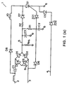
- a loss of neutral protection circuit indicated generally by the reference numeral 1.
- the protection circuit 1 has a line lead 2, a neutral lead 3 and an earth lead 4.
- a bridge rectifier comprising diodes D1 to D4 is connected across the line lead 2 and the neutral lead 3 for DC output at a positive terminal 5 and a negative terminal 6.
- a load connected across these output terminals is represented in the drawing by Req.
- a capacitor C1 is connected in the line lead 2 to provide isolation from a high DC voltage, such as in a dielectric or insulation test.
- the protection circuit 1 further includes a circuit breaker comprising a solenoid 10 operating a mechanism (not shown) which opens contacts in the line lead 2, connected to an SCR Q1, the gate of which is connected to a Zener diode ZD1.
- the cathode of the SCR Q1 is connected to both the earth lead 4 via a diode D5 and to the negative rectifier terminal 6.
- a Zener diode ZD2 is connected in the earth lead 4.
- the circuit 1 further provides control means via a capacitor C2 connected at one side to the DC negative terminal 6 and at the other side to the DC positive terminal 5 through a resistor R1. This side of the capacitor C2 is also connected to the Zener diode ZD1 and to the anode of a diode D6 which is, in turn, connected to the neutral lead 3.
- a holding circuit for the SCR Q1 is provided by a capacitor C3 across the DC positive and negative terminals 5 and 6, and connected to the anode of the SCR Q1 by a resistor R2 and a diode D7.
- the discharging path through D6 is not available to the capacitor C2 and it continues to charge until the breakdown voltage of ZD1 is exceeded.
- the solenoid 10 is energized to open the line lead 2 by a current flowing through the diode D8, solenoid 10, SCR Q1, diode D5 and the Zener diode ZD2 to earth.
- the diode D5 isolates the circuit during the negative half cycle and the Zener diode ZD2 prevents current flow to earth during normal operation without loss of neutral, which current flow may cause tripping of upstream ELCB'S.
- the time delay between loss of neutral and operation of the circuit breaker is set by the values of the capacitor C2, the resistor R1 and the Zener diode ZD1.
- the diode D5 acts both to provide a current path for the SCR Q1 to earth and to provide for continued rectification with line and earth inputs.
- the holding circuit formed by the capacitor C3, the resistor R2 and the diode D7 holds the SCR Q1 in conduction during the negative half cycle. This is achieved by storage of charge in C3.
- the protection circuit 15 includes a storage capacitor C4 connected between the output of the diode D8 and earth.
- the diode D5 and the Zener diode ZD2 are replaced by a resistor R8, and the capacitor C3, the resistor R2 and the diode D7 are deleted.
- the storage capacitor C4 holds the SCR Q1 in the conducting state during the negative half cycle and thus there is no need for continued rectification, as with the circuit 1.
- the resistor R8 provides a reference to earth, and in the event of loss of neutral, the capacitor C2 charges through R1 and R8.
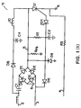
- Fig.2 there is illustrated an alternative construction of loss of neutral protection circuit, indicated generally by the reference numeral 20. Parts similar to those described in Fig.1 are assigned the same reference numerals and letters. The differences between the circuits 1 and 20 are that in the latter the solenoid 10 is replaced by an alarm indicator 21 which may be a light or sound emitter. A separate solenoid 22 and SCR Q2 are connected between the line lead 2 and earth for opening of the line lead on detection of a ground fault by a ground fault sensing circuit 23 of any conventional construction.
- the circuit 20 allows continuity of operation on the occurrence of a loss of neutral and will open the line lead 2 only in the event of a ground fault. It is envisaged, therefore, that the circuit 20 would be useful where continuity of operation of the load is important.
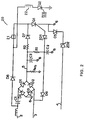
- the protection circuits of the invention may include other fault detection circuits connected to the circuit breaker and referring to Fig. 3 there is illustrated such a protection circuit, indicated generally by the reference numeral 30. Parts similar to or which serve the same function as parts described with reference to the previous drawings are identified similarly.
- loss of neutral protection is provided for a three phase supply connected to line leads A, B and C which have coupling capacitors C31, C32 and C33, respectively.
- DC power is provided by two bridge rectifiers formed by diodes D31 to D34 and D35 to D38. The positive output from both bridge rectifiers are connected at a positive terminal 32.
- a ground fault detection circuit 31 (indicted by interrupted lines) is arranged to independently trigger the SCR Q1 on detection of a ground fault.
- the ground fault detection circuit 31 is of conventional construction and requires no further description.
- the capacitor C2 remains at almost ground potential except when a loss of neutral occurs, in which case it will charge through R1 and trigger the SCR Q1 through the Zener diode ZD1.
- the time delay is determined by the values of the resistor R1, the capacitor C2 and the Zener diode ZD1.
- the solenoid 10 will be supplied by current from one of the phases.
- an energizing circuit for the circuit breaker will be completed through the solenoid 10, the SCR Q1, the diode D5 and the Zener diode ZD2 to earth.
- operation of the circuit breaker may also be in response to a ground fault and in this case the energizing circuit would be completed through the solenoid 10, the SCR Q1, and the bridge rectifier negative output to neutral.
- the protection circuit 40 does not include a capacitor, diode and resistor arrangement for detection of loss of neutral.
- a sense circuit of any conventional construction is provided with power through the coupling capacitor C1, the diode D1, the diode D5 and the Zener diode ZD2.
- any type of fault detection circuit may be included in addition to the loss of neutral detection circuit.
- any type of circuit breaker may be used, for example,the SCR may be replaced by a VMOS transistor.
- the protection circuit may be adapted to provide loss of ground protection in addition to or instead of, loss of neutral protection.
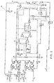
- a protection circuit 50 to provide loss of neutral and/or ground protection is illustrated in Fig. 5, in which parts similar to those described with reference to the previous drawings are identified by the same reference numerals.
- the protection circuit 50 includes a capacitor C6 connected at one side to the positive terminal 5 by a resistor R3 and on the other side to the negative terminal 6, in similar manner to the capacitor C2. Instead of being connected to the neutral lead 3, however, the capacitor C6 is connected to the ground lead 4 via a diode D51.
- a pair of diodes D52 and D53 provide rectification for the connection of the capacitors C2 and C6 to the Zener diode ZD1.
- the positive terminal 5 is connected to the earth via a reverse biased diode D50.
- the capacitors C2 and C6 are charged through R1 and R3 respectively during the negative half cycle and are discharged during the positive half cycle through D6 and D51, respectively.
- tripping of the SCR Q 1 is as described above and on loss of ground, the discharge of C6 during the positive half cycle does not occur and when the voltage across C6 exceeds the Zener voltage of ZD1 and the signal diode D53, the SCR Q 1 is triggered.
- an energizing path for the 8CR Q 1 is completed to the negative lead, as in normal operation.
- the invention provides an extremely simple loss of neutral or ground protection circuit with a small number of simple components, and it is thus inexpensive and reliable.
- the fact that there is an adjustable time delay before operation of the circuit breaker is a distinct advantage where continuity of operation of the load is important in the event of momentary loss of neutral or ground. Finally, this time delay may be easily set by appropriate selection of the relevant components.
Landscapes
- Emergency Protection Circuit Devices (AREA)
Abstract
Claims (13)
- Un circuit de protection contre la perte de neutre ou de mise à la terre dans un système comportant un fil de ligne (2), un fil de neutre (3) et un fil de terre (4) entre une source de courant et une charge (Req), ledit circuit de protection comprenant : un dispositif (10, 21) pour interrompre le fil de ligne (2) ou indiquer un défaut lors de la réception d'un signal d'excitation ; caractérisé par un moyen de commande pour commander le fonctionnement dudit dispositif (10, 21), ledit moyen de commande comprenant un circuit capacitif (R1, C2 ; R3, C6) arrangé pour être chargé par le fil de ligne (2), et pour ensuite être déchargé dans le fil de neutre (3) pour la détection de perte de neutre, ou dans le fil de terre (4) pour la détection de perte de mise à la terre, dans lequel le circuit capacitif (R1, C2) est continûment chargé pendant une moitié de cycle de fonctionnement, et continûment déchargé pendant l'autre moitié de cycle de fonctionnement, la perte de neutre sur le fil de neutre (3), ou de mise à la terre sur le fil de terre (4), empêchant la décharge continue du circuit capacitif (R1, C2 ; R3, C6), afin de produire un signal d'excitation pour ledit dispositif (10, 21) après un temps de retard établi par un circuit de maintien (C3, R2).
- Un circuit de protection selon la revendication 1, dans lequel ledit signal d'excitation est un signal en tension excédant un niveau de tension de déclenchement.
- Un circuit de protection selon la revendication 2, dans lequel ledit niveau de tension de déclenchement du signal d'excitation appliqué audit dispositif comprenant le disjoncteur (10) est établi par un régulateur de tension (ZD1) relié audit disjoncteur (10).
- Un circuit de protection selon la revendication 3, dans lequel ledit régulateur de tension est une diode Zener (ZD1).
- Un circuit de protection selon l'une quelconque des revendications précédentes, comprenant en outre un redresseur pleine onde (D1, D2, D3, D4) connecté aux fils de ligne (2) et de neutre (3) pour fournir du courant continu à une charge (Req) par l'intermédiaire de bornes d'alimentation positive (5) et négative (6), dans lequel le circuit capacitif (R1, C2 ; R3, C6) est connecté dans la sortie du redresseur pleine onde (D1, D2, D3, D4), et est relié au fil de neutre (3) ou au fil de terre (4) par l'intermédiaire d'une diode polarisée dans le sens direct (D6, D5).
- Un circuit de protection selon la revendication 5, dans lequel ledit circuit capacitif est relié à la borne positive (5) du redresseur pleine onde par l'intermédiaire d'un circuit résistif (R1), de sorte qu'en service, le circuit capacitif (C2) se charge par l'intermédiaire du circuit résistif (R1).
- Un circuit de protection selon la revendication 1, dans lequel ledit dispositif (10) est couplé au fil de terre (4) par un régulateur de tension (ZD2, R8) pour empêcher le courant de passer à la terre, sauf lors du fonctionnement dudit dispositif (10).
- Un circuit de protection selon la revendication 7, dans lequel ledit régulateur de tension est une diode Zener (ZD2).
- Un circuit de protection selon la revendication 7, dans lequel ledit régulateur de tension est un résistor (R8).
- Un circuit de protection selon la revendication 1, dans lequel ledit dispositif comprend un thyristor au silicium (Q1) fonctionnellement relié à un solénoïde (10) arrangé pour interrompre le fil de ligne (2), le signal d'excitation étant appliqué à la gâchette dudit thyristor au silicium (Q1).
- Un circuit de protection selon la revendication 10, dans lequel un circuit de stockage capacitif (C3, R2) est relié à l'anode dudit thyristor au silicium (Q1) pour maintenir ledit thyristor au silicium (Q1) à l'état passant pendant la moitié de cycle négative de la source en courant alternatif.
- Un circuit de protection selon la revendication 11, dans lequel le fil de ligne (2) est relié à l'anode du thyristor au silicium (Q1) via une diode polarisée dans le sens direct (D7), et le circuit capacitif de stockage (C2, R2) est connecté entre la cathode de la diode (D7) et le fil de terre (4).
- Un circuit de protection selon la revendication 1, dans lequel le fil de ligne (2) est connecté à une source de courant alternatif par l'intermédiaire d'un condensateur de liaison (C1) pour assurer la protection vis-à-vis du courant continu appliqué au circuit.
Applications Claiming Priority (2)
| Application Number | Priority Date | Filing Date | Title |
|---|---|---|---|
| US07/340,302 US4931893A (en) | 1989-04-19 | 1989-04-19 | Loss of neutral or ground protection circuit |
| PCT/US1990/002482 WO1991017596A1 (fr) | 1989-04-19 | 1990-05-04 | Circuit de protection contre la perte de neutre ou de mise a la terre |
Publications (3)
| Publication Number | Publication Date |
|---|---|
| EP0480937A1 EP0480937A1 (fr) | 1992-04-22 |
| EP0480937A4 EP0480937A4 (en) | 1993-06-09 |
| EP0480937B1 true EP0480937B1 (fr) | 1994-10-12 |
Family
ID=23332766
Family Applications (1)
| Application Number | Title | Priority Date | Filing Date |
|---|---|---|---|
| EP90907854A Expired - Lifetime EP0480937B1 (fr) | 1989-04-19 | 1990-05-04 | Circuit de protection contre la perte de neutre ou de mise a la terre |
Country Status (5)
| Country | Link |
|---|---|
| US (1) | US4931893A (fr) |
| EP (1) | EP0480937B1 (fr) |
| JP (1) | JPH05501043A (fr) |
| DE (1) | DE69013347T2 (fr) |
| WO (1) | WO1991017596A1 (fr) |
Families Citing this family (28)
| Publication number | Priority date | Publication date | Assignee | Title |
|---|---|---|---|---|
| US4933801A (en) * | 1989-04-19 | 1990-06-12 | Square D Company | Ground fault circuit interrupter |
| US4994933A (en) * | 1989-04-19 | 1991-02-19 | Square D Company | Ground fault circuit interrupter having loss of neutral or loss of ground protection |
| JP2504586B2 (ja) * | 1989-10-31 | 1996-06-05 | 東芝マイクロエレクトロニクス株式会社 | 接地外れ保護回路を有する電子回路装置 |
| US5200873A (en) * | 1990-12-05 | 1993-04-06 | Square D Company | Circuit interrupter |
| US5191318A (en) * | 1991-07-08 | 1993-03-02 | Square D Company | Loss of neutral detecting circuit |
| CA2093061C (fr) * | 1992-07-22 | 2005-02-15 | Raymond H. Legatti | Dispositif de protection contre les fuites de courant adapte a une variete d'applications domestiques et internationales |
| FR2697385B1 (fr) * | 1992-10-26 | 1994-11-18 | Electricite De France | Dispositif de protection contre les anomalies sur la ligne de neutre d'un réseau électrique. |
| US5418678A (en) * | 1993-09-02 | 1995-05-23 | Hubbell Incorporated | Manually set ground fault circuit interrupter |
| US5973896A (en) * | 1995-05-26 | 1999-10-26 | David C. Nemir | Shock and arc protection device for an electrical distribution system |
| US5844759A (en) * | 1995-05-26 | 1998-12-01 | David C. Nemir | Electrical fault interrupter |
| US6560079B1 (en) | 1995-05-26 | 2003-05-06 | X-L Synergy | Ground loss detection for electrical appliances |
| IT1276444B1 (it) * | 1995-06-27 | 1997-10-31 | Fiat Auto Spa | Dispositivo di controllo della messa a terra di un utilizzatore elettrico, in particolare della carrozzeria nei veicoli elettrici. |
| US5949197A (en) * | 1997-06-30 | 1999-09-07 | Everbrite, Inc. | Apparatus and method for dimming a gas discharge lamp |
| US6542347B1 (en) | 2000-07-31 | 2003-04-01 | Danny J. Young | Apparatus for protecting electronic equipment and related methods |
| US8309118B2 (en) * | 2001-09-28 | 2012-11-13 | Mcneil-Ppc, Inc. | Film forming compositions containing sucralose |
| GB2373112B (en) * | 2002-03-20 | 2003-03-05 | Roger Thomas Ronald Pilling | Method and apparatus for protecting against hazardous voltages on electrical installations |
| FR2842663B1 (fr) * | 2002-07-18 | 2004-09-10 | Schneider Electric Ind Sa | Dispositif de surveillance de rupture de neutre et de terre, et appareil de coupure electrique comportant un tel dispositif |
| RU2230415C1 (ru) * | 2002-10-17 | 2004-06-10 | Южно-Уральский государственный университет | Устройство контроля непрерывности нулевого проводника в воздушных линиях 0,4 кв |
| US7400476B1 (en) | 2003-12-10 | 2008-07-15 | Hull Jr Vernon M | Safety device for prevention of electrical shocks |
| US20070258175A1 (en) * | 2006-05-08 | 2007-11-08 | Montgomery Steven R | Method and apparatus for open neutral fault detection |
| RU2348094C2 (ru) * | 2007-04-17 | 2009-02-27 | ФГОУ ВПО Костромская государственная сельскохозяйственная академия | УСТРОЙСТВО КОНТРОЛЯ НЕПРЕРЫВНОСТИ НУЛЕВЫХ ПРОВОДНИКОВ В ЛИНИЯХ 0,38 кВ |
| US8207394B2 (en) * | 2007-11-13 | 2012-06-26 | Kimberly-Clark Worldwide, Inc. | Induction coil wetness sensor for an absorbent article |
| US8106670B2 (en) * | 2008-11-24 | 2012-01-31 | Schneider Electric USA, Inc. | Two pole circuit breaker voltage monitoring integration |
| US8649143B2 (en) * | 2008-11-24 | 2014-02-11 | Schneider Electric USA, Inc. | Improper voltage detection for electronic circuit breaker |
| US8964345B2 (en) | 2012-07-02 | 2015-02-24 | Reliance Controls Corporation | Semiautomatic transfer switch with open neutral protection |
| US8891219B2 (en) | 2012-07-02 | 2014-11-18 | Reliance Controls Corporation | Open neutral protection |
| WO2015157774A1 (fr) | 2014-04-11 | 2015-10-15 | Wood Stone Corporation | Systèmes et procédés de contrôle de qualité de mise à la terre |
| RU2599379C2 (ru) * | 2015-01-12 | 2016-10-10 | федеральное государственное казенное военное образовательное учреждение высшего образования "Краснодарское высшее военное училище имени генерала армии С.М. Штеменко" Министерства обороны Российской Федерации | Устройство для контроля цепи заземления технических средств обработки информации |
Family Cites Families (6)
| Publication number | Priority date | Publication date | Assignee | Title |
|---|---|---|---|---|
| US3922659A (en) * | 1974-07-29 | 1975-11-25 | Baxter Laboratories Inc | Power line fault indicating system employing a neon lamp oscillator |
| US4011483A (en) * | 1974-11-07 | 1977-03-08 | The Ohio Brass Company | Ground wire monitoring system |
| US3987341A (en) * | 1975-04-03 | 1976-10-19 | I-T-E Imperial Corporation | Open neutral protection |
| US3973171A (en) * | 1975-05-19 | 1976-08-03 | General Electric Company | Ground fault circuit interrupting device with grounded neutral detection |
| US4598331A (en) * | 1984-07-30 | 1986-07-01 | Technology Research Corporation | Ground fault current interrupter circuit with open neutral and ground lead protection |
| GB2224404B (en) * | 1988-10-25 | 1993-03-17 | Shakira Ltd | Residual current device |
-
1989
- 1989-04-19 US US07/340,302 patent/US4931893A/en not_active Expired - Lifetime
-
1990
- 1990-05-04 DE DE69013347T patent/DE69013347T2/de not_active Expired - Fee Related
- 1990-05-04 EP EP90907854A patent/EP0480937B1/fr not_active Expired - Lifetime
- 1990-05-04 JP JP2507575A patent/JPH05501043A/ja active Pending
- 1990-05-04 WO PCT/US1990/002482 patent/WO1991017596A1/fr not_active Ceased
Also Published As
| Publication number | Publication date |
|---|---|
| DE69013347D1 (de) | 1994-11-17 |
| EP0480937A1 (fr) | 1992-04-22 |
| EP0480937A4 (en) | 1993-06-09 |
| US4931893A (en) | 1990-06-05 |
| JPH05501043A (ja) | 1993-02-25 |
| DE69013347T2 (de) | 1995-05-18 |
| WO1991017596A1 (fr) | 1991-11-14 |
Similar Documents
| Publication | Publication Date | Title |
|---|---|---|
| EP0480937B1 (fr) | Circuit de protection contre la perte de neutre ou de mise a la terre | |
| US4363064A (en) | Overcurrent protection system | |
| US4223365A (en) | Auto resetting switchgear trip indicator circuits | |
| US4027203A (en) | Protective switch device for electrical distribution systems | |
| EP0108279A1 (fr) | Disjoncteur pour courant continu à haute tension | |
| US4352138A (en) | Backup trip circuit for a circuit breaker | |
| EP0483164B1 (fr) | Coupe-circuit en cas de defaut a la terre | |
| US4876496A (en) | Current supplying device | |
| EP0484341B1 (fr) | Alimentation electrique | |
| GB2224404A (en) | Residual current device with missing neutral protection | |
| US3739229A (en) | Overcurrent sensing and restraint control for sectionalizing switch | |
| JPH10191552A (ja) | 漏電遮断器の過電圧検出回路 | |
| US3602776A (en) | Quick resetting apparatus | |
| IE67969B1 (en) | A loss of neutral or ground protection circuit | |
| CA2016217A1 (fr) | Circuit de protection contre les defaillances dans les circuits de mise a la masse ou a la terre | |
| JP3374952B2 (ja) | 直列形インバータ回路の保護方法 | |
| JP3334008B2 (ja) | 単相3線式配線の中性線欠相検出装置 | |
| JPS6245767B2 (fr) | ||
| KR100439890B1 (ko) | 결상시도 지락보호가 가능한 누전차단기 | |
| KR860001479B1 (ko) | 배전선로 고장구간 자동 개방 차단 장치 | |
| RU1823061C (ru) | Устройство дл контрол сопротивлени изол ции электрических цепей | |
| JPS63161815A (ja) | インバ−タ装置の地絡保護装置 | |
| GB2218286A (en) | Malfunction indicator with reset arrangement | |
| JPS6245766B2 (fr) | ||
| US4363062A (en) | Inductive voltage transformer and circuit therefor |
Legal Events
| Date | Code | Title | Description |
|---|---|---|---|
| PUAI | Public reference made under article 153(3) epc to a published international application that has entered the european phase |
Free format text: ORIGINAL CODE: 0009012 |
|
| 17P | Request for examination filed |
Effective date: 19920124 |
|
| AK | Designated contracting states |
Kind code of ref document: A1 Designated state(s): DE FR GB IT |
|
| A4 | Supplementary search report drawn up and despatched |
Effective date: 19930419 |
|
| AK | Designated contracting states |
Kind code of ref document: A4 Designated state(s): DE FR GB IT |
|
| 17Q | First examination report despatched |
Effective date: 19931116 |
|
| GRAA | (expected) grant |
Free format text: ORIGINAL CODE: 0009210 |
|
| ITF | It: translation for a ep patent filed | ||
| AK | Designated contracting states |
Kind code of ref document: B1 Designated state(s): DE FR GB IT |
|
| REF | Corresponds to: |
Ref document number: 69013347 Country of ref document: DE Date of ref document: 19941117 |
|
| ET | Fr: translation filed | ||
| PLBE | No opposition filed within time limit |
Free format text: ORIGINAL CODE: 0009261 |
|
| STAA | Information on the status of an ep patent application or granted ep patent |
Free format text: STATUS: NO OPPOSITION FILED WITHIN TIME LIMIT |
|
| 26N | No opposition filed | ||
| REG | Reference to a national code |
Ref country code: GB Ref legal event code: IF02 |
|
| PGFP | Annual fee paid to national office [announced via postgrant information from national office to epo] |
Ref country code: DE Payment date: 20030530 Year of fee payment: 14 |
|
| PG25 | Lapsed in a contracting state [announced via postgrant information from national office to epo] |
Ref country code: DE Free format text: LAPSE BECAUSE OF NON-PAYMENT OF DUE FEES Effective date: 20041201 |
|
| PGFP | Annual fee paid to national office [announced via postgrant information from national office to epo] |
Ref country code: FR Payment date: 20090507 Year of fee payment: 20 Ref country code: IT Payment date: 20090515 Year of fee payment: 20 |
|
| PGFP | Annual fee paid to national office [announced via postgrant information from national office to epo] |
Ref country code: GB Payment date: 20090407 Year of fee payment: 20 |
|
| REG | Reference to a national code |
Ref country code: GB Ref legal event code: PE20 Expiry date: 20100503 |
|
| PG25 | Lapsed in a contracting state [announced via postgrant information from national office to epo] |
Ref country code: GB Free format text: LAPSE BECAUSE OF EXPIRATION OF PROTECTION Effective date: 20100503 |