EP0481077B1 - Einrichtung zur messung der position einer unterirdischen grabmaschine - Google Patents
Einrichtung zur messung der position einer unterirdischen grabmaschine Download PDFInfo
- Publication number
- EP0481077B1 EP0481077B1 EP90909833A EP90909833A EP0481077B1 EP 0481077 B1 EP0481077 B1 EP 0481077B1 EP 90909833 A EP90909833 A EP 90909833A EP 90909833 A EP90909833 A EP 90909833A EP 0481077 B1 EP0481077 B1 EP 0481077B1
- Authority
- EP
- European Patent Office
- Prior art keywords
- cables
- sets
- receiver
- magnetic field
- cable
- Prior art date
- Legal status (The legal status is an assumption and is not a legal conclusion. Google has not performed a legal analysis and makes no representation as to the accuracy of the status listed.)
- Expired - Lifetime
Links
- 230000005291 magnetic effect Effects 0.000 claims abstract description 47
- 230000005611 electricity Effects 0.000 claims description 2
- 238000000034 method Methods 0.000 description 11
- 238000006073 displacement reaction Methods 0.000 description 8
- 238000010586 diagram Methods 0.000 description 4
- 238000009412 basement excavation Methods 0.000 description 3
- 238000001514 detection method Methods 0.000 description 3
- 238000005259 measurement Methods 0.000 description 2
- 230000003287 optical effect Effects 0.000 description 2
- 230000001427 coherent effect Effects 0.000 description 1
- 238000010276 construction Methods 0.000 description 1
- 238000007796 conventional method Methods 0.000 description 1
- 230000007423 decrease Effects 0.000 description 1
- 230000000694 effects Effects 0.000 description 1
- 230000001939 inductive effect Effects 0.000 description 1
- 230000017105 transposition Effects 0.000 description 1
- 230000005641 tunneling Effects 0.000 description 1
Images


Classifications
-
- G—PHYSICS
- G01—MEASURING; TESTING
- G01C—MEASURING DISTANCES, LEVELS OR BEARINGS; SURVEYING; NAVIGATION; GYROSCOPIC INSTRUMENTS; PHOTOGRAMMETRY OR VIDEOGRAMMETRY
- G01C15/00—Surveying instruments or accessories not provided for in groups G01C1/00 - G01C13/00
-
- E—FIXED CONSTRUCTIONS
- E21—EARTH OR ROCK DRILLING; MINING
- E21D—SHAFTS; TUNNELS; GALLERIES; LARGE UNDERGROUND CHAMBERS
- E21D9/00—Tunnels or galleries, with or without linings; Methods or apparatus for making thereof; Layout of tunnels or galleries
- E21D9/003—Arrangement of measuring or indicating devices for use during driving of tunnels, e.g. for guiding machines
-
- E—FIXED CONSTRUCTIONS
- E21—EARTH OR ROCK DRILLING; MINING
- E21B—EARTH OR ROCK DRILLING; OBTAINING OIL, GAS, WATER, SOLUBLE OR MELTABLE MATERIALS OR A SLURRY OF MINERALS FROM WELLS
- E21B47/00—Survey of boreholes or wells
- E21B47/02—Determining slope or direction
- E21B47/022—Determining slope or direction of the borehole, e.g. using geomagnetism
- E21B47/0228—Determining slope or direction of the borehole, e.g. using geomagnetism using electromagnetic energy or detectors therefor
- E21B47/0232—Determining slope or direction of the borehole, e.g. using geomagnetism using electromagnetic energy or detectors therefor at least one of the energy sources or one of the detectors being located on or above the ground surface
Definitions
- the present invention relates to a position measuring apparatus of an underground excavator and, more particularly, to a position measuring apparatus of an underground excavator, such as a shield machine, which excavates underground.
- the position of the machine relative to a reference position is obtained with combinations of an direction gyro and a pressure-type subsidence recorder, and of a clinometer and driving distance recorder (referring to length of a segment).
- the inventor has proposed (in Japanese Pat. Laid-Open No. 62-169012) a method in which a magnetic field generating cable is provided on the ground surface and a magnetic field detecting element is provided in an underground excavator, and in which a magnetic field generated from the cable is detected by the element and thus displacement in the horizontal position of the underground excavator is measured.
- the inside-tunnel survey method employing a transit or the like is used to survey a to-be-bored tunnel which is curved or bent, many station points are required, increasing the number of work stages. Thus, such a method is not practical. If the method employing a laser beam is used to survey a curved or bent tunnel, the laser beam may not reach a target in some cases. In such cases, an optical oscillating device has to be moved to an appropriate position.
- a method employing a gyro has a problem in that because accumulated error becomes large, it is not suitable for a long-distance excavation. Further, a method employing a magnetic field has a problem in that though it measures horizontal displacement, it cannot measure excavating distance (such as a distance of excavation from a vertical shaft).
- the present invention provides a position measuring apparatus comprising: a transmitter including at least two sets of cables which are provided under or on the ground and around which AC magnetic fields are generated by electricity from an AC power source; a receiver which receives the AC magnetic fields; a computing unit which identifies signals from the receiver and which calculates the position of the underground excavator.
- Said invention is characterized by a position measuring apparatus in which the two sets of cables are substantially perpendicular to each other.
- the receiver includes two sets of magnetic field detecting elements which are substantially perpendicular to each other whereby the receiver is supported by a receiver supporting device which rotates, according to signals from a direction detecting device, so as to maintain these elements at specified angles to the two sets of cables.
- the present invention provides a position measuring apparatus comprising a timing output circuit which controls so that AC magnetic fields are generated alternately from the two sets of cables.
- the magnetic fields generated by supplying AC currents to at least two sets of cables provided on or under the ground are received by the two sets of magnetic field detecting elements which intersect each other at a specified angle on the receiver supporting device which is controlled so as to face in a constant direction, and such magnetic field reception by these elements provides a level of voltage, by which the position on a horizontal plane of an underground excavator is easily and accurately detected.
- a position measuring apparatus as described above may include two more sets of cables and another receiver, so that it can measure depth.
- the depth may also be measured by a conventional pressure-type subsidence recorder or a combination of a clinometer and a driving distance recorder.
- FIG. 4 is a schematic plan view.
- a cable 10a is parallel (x-axis direction) to the direction of excavation.
- the other cable 10b is perpendicular (y-axis direction) to the direction of excavating and substantially perpendicular to the cable 10a.
- One side of the cable 10a touches one side of the cable 10b.
- a receiver 30 has two magnetic field detecting elements S1, S2 whose magnetic field detecting directions intersect perpendicularly and are angled at 45° to vertical planes of the cables 10a, 10b.
- FIG. 5 is a schematic perspective view of what is shown in FIG. 4.
- An AC power source 11a supplies the cable 10a with voltage e1, current i1 and frequency ⁇ 1
- another AC power source 11b supplies the cable 10b with voltage e2, current i2 and frequency ⁇ 2.
- parameters are determined as the following: 2W: distance between wires of the cables 10a and distance between wires of the cables 10b X: distance of the magnetic field detecting elements S1 and S2 from the cable 10b Y: distance of the magnetic field detecting elements S1 and S2 from the cable 10a dX: horizontal displacement of the magnetic field detecting elements S1 and S2 from the center of the cable 10a dY: horizontal displacement of the magnetic field detecting elements S1 and S2 from the center of the cable 10b ⁇ 1: angle between the magnetic field detecting element S1 and a line perpendicular to the cable 10a ⁇ 2: angle between the magnetic field detecting element S2 and a line perpendicular to the cable 10a V11: voltage induced in the magnetic field detecting element S1 by the cable 10a V21: voltage induced in the magnetic field detecting element S2 by the cable 10a V12: voltage induced in the magnetic field detecting element S1 by the cable 10b V22: voltage induced in the magnetic field detecting element S
- the cable 10a and the cable 10b have the same distance between wires (2W) and the one side of a cable is touched to one side of the other cable in the above example, the distance of the receiver 30 from the underground excavator can naturally be obtained if the between-wire distances of the two cables are different from each other and the sides of the cables which are touched in the above example are separated or intersected.
- FIG. 1 shows a plan view of a position measuring apparatus of an underground excavator 20 according to the present invention constructed on the basis of the above described principle.
- FIG. 2 shows a detailed block diagram of the position measuring apparatus.
- the figures show: a start vertical shaft SH; an end vertical shaft EH; a transmitter 10 including two sets of cables, one being a cable 10a provided between the start vertical shaft SH and the end vertical shaft EH, and the other being a cable 10b provided inside the start vertical shaft SH; an underground excavator 20; a receiver 30 carried by the underground excavator 20 and including two magnetic field detecting elements S1 and S2 whose magnetic detecting directions are perpendicular to each other; an AD converter 35; and a receiver supporting device 40 which rotates according to signals from an direction detecting device 50 in order to position the receiver 30 at a certain angle to the two sets of transmitters.
- the direction detecting device 50 detects the direction in which the underground excavator 20 is driven, and controls the rotation of the receiver supporting device 40.
- a computing unit 60 calculates the position of the underground excavator 20 based on signals which the device 60 receives.
- a indicator 70 indicates the position of the underground excavator 20 according to the calculations by the computing unit 60.
- a depth measuring device 100 employs a pressure-type subsidence recorder or the like, according to this embodiment, to measure depth.
- the cables 10a and 10b of the transmitter 10 are perpendicular to each other and are supplied with power by AC power sources 11a and 11b respectively.
- the receiver 30 includes: two magnetic field detecting elements S1 and S2; two filters f1 and f2 connected to these elements S1 and S2; and receiving amplifiers Am1 and Am2 connected to the filters f1, f2.
- the receiver 30 is connected through the AD converter 35 to the computing unit 60.
- the receiver supporting device 40 is rotated by a pulse motor 42 which is controlled by a motor controller 41 according to the signals from the direction detecting device 50, in order to maintain the positions of the magnetic field detecting elements S1, S2 or the like at constant angles.
- the magnetic field detecting elements S1, S2 are placed on a table (not shown).
- the AC power source 11a supplies the cable 10a with an AC current at a frequency ⁇ 1.
- the AC power source 11b supplies the cable 10b with an AC current at a frequency ⁇ 2.
- the AC currents thus generate magnetic fields around the cables 10a and 10b.
- the magnetic fields are detected by the magnetic field detecting elements S1 and S2.
- the filters f1 and f2 determine from which cable the magnetic field inducing the voltage in each of the magnetic field detecting elements is originated.
- the signals from the filters f1 and f2 are amplified by the receiving amplifiers Am1 and Am2. Then, the signals are converted into direct currents.
- the converted signals are converted into digital values by the AD converter 35.
- the computing unit 60 performs the calculation described above based on these signals, and obtains X and Y-coordinates of the position of the position measuring apparatus 20 of the underground excavator 30.
- the computing unit 60 also controls the receiver supporting device 40, according to the signals from the direction detecting device 50, so that the two magnetic fields detecting elements S1 and S2 will be at constant angles.
- FIG. 3 is a block diagram of a position measuring apparatus 250 of an underground excavator 20 according to the second embodiment of the present invention.
- the parts equivalent to those of the first embodiment are denoted by the same numerals as in the first embodiment, and the description thereof will not be repeated.
- Two sets of cables 110a and 110b of a transmitter 110 are substantially perpendicular to each other, and are alternately, according to signals from a timing output circuit 200, supplied with the same current (voltage e c , current i c , frequency ⁇ c ) from AC power sources 111a and 111b.
- a receiver 120 includes two magnetic field detecting elements, such as coils, S1 and S2; filters f1 connected to each of these elements S1 and S2; receiving amplifiers Am1 connected to the filters f1.
- the receiver 120 is connected through an AD converter 35 to a computing unit 60.
- the AC power sources 111a and 111b supply a frequency ⁇ 1 to the cables 110a and 110b alternately according to the signals from the timing output circuit 200.
- AC magnetic fields are thus generated in concentric configurations about the cables 110a and 110b.
- the magnetics fields are detected by the magnetic field detecting elements S1 and S2.
- the detection signals are shaped by the filters f1. Because the signals from the timing output circuit 200 are inputted to the computing unit 60, it can be determined from which cable the detected magnetic field is originated.
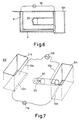
- FIG. 6 illustrates an application of the present invention, wherein a horizontal shaft H is provided between a start vertical shaft SH and a cable vertical shaft V and a cable 10 is provided in these vertical shafts.
- FIG. 7 illustrates another application, wherein a cable 10a is provided underground between a start vertical shaft SH and an end vertical shaft EH and a cable 10b is provided on the ground surface therebetween.
- a vertical shaft may be bored not only from the ground surface but from an underground portion of a building.
- a cable may be grounded at a lower portion of a vertical shaft, providing similar effects to those in the above embodiments.
- a position measuring apparatus advantageously detects automatically, continuously and instantaneously the horizontal position of an excavator, such as a shield machine, excavating underground.
- a position measuring apparatus can be suitably used for boring a tunnel which is sharply curved or continuously curved with its depth varying greatly.
Landscapes
- Engineering & Computer Science (AREA)
- Mining & Mineral Resources (AREA)
- Physics & Mathematics (AREA)
- Life Sciences & Earth Sciences (AREA)
- Geology (AREA)
- Environmental & Geological Engineering (AREA)
- General Life Sciences & Earth Sciences (AREA)
- Geochemistry & Mineralogy (AREA)
- Electromagnetism (AREA)
- Geophysics (AREA)
- Fluid Mechanics (AREA)
- General Physics & Mathematics (AREA)
- Radar, Positioning & Navigation (AREA)
- Remote Sensing (AREA)
- Excavating Of Shafts Or Tunnels (AREA)
- Geophysics And Detection Of Objects (AREA)
- Measurement Of Length, Angles, Or The Like Using Electric Or Magnetic Means (AREA)
- Position Fixing By Use Of Radio Waves (AREA)
Claims (2)
- Positionsmeßgerät einer Maschine für unterirdischen Aushub, der folgendes umfaßt: einen Sender 10, der mindestens zwei Kabelsätze 10a und 10b enthält, die unter oder auf der Erdoberfläche verlegt werden und um die herum durch die Elektrizität aus einer Wechselstromquelle magnetische Wechselfelder erzeugt werden; einen Empfänger 30, der die magnetischen Wechselfelder vom Sender 10 empfängt; sowie eine Recheneinheit 60, die die Signale vom Empfänger 30 identifiziert und die Position der Maschine für unterirdischen Aushub 20 berechnet, gekennzeichnet dadurch, daß diese beiden Kabelsätze 10a und 10b des Senders 10 im wesentlichen rechtwinklig zueinander verlaufen; daß der Empfänger 30 zwei Sätze von Magnetfeldmeßfühlern S₁ und S₂ enthält, die so positioniert sind, daß die Richtungen, in denen diese Meßfühler S₁ und S₂ die magnetsichen Wechselfelder von den beiden Kabelsätzen 10a und 10b des Senders 10 messen, im wesentlichen rechtwinklig zueinander liegen, und daß der Empfänger 30 auf einer Empfängerstützvorrichtung 40 aufliegt, die sich entsprechend den Signalen eines Richtungsmeßgerätes 50 dreht, damit sich die beiden Sätze von Meßfühlem S₁ und S₂ stets in festgelegten Winkeln zu den beiden Kabelsätzen 10a und 10b befinden.
- Positionsmeßgerät einer Maschine für unterirdischen Aushub nach Anspruch 1, in dem eine Taktschaltung zur Zeitsteuerung 200 zwischen dem Sender 10 und der Recheneinheit 60 installiert ist und die Taktschaltung zur Zeitsteuerung 200 Signale abgibt, damit die zwei Kabelsätze 10a und 10b abwechselnd Wechselstrom empfangen, so daß magnetische Wechselfelder abwechselnd um die Kabel 10a und 10b erzeugt werden.
Applications Claiming Priority (3)
| Application Number | Priority Date | Filing Date | Title |
|---|---|---|---|
| JP170422/89 | 1989-06-30 | ||
| JP1170422A JPH0335114A (ja) | 1989-06-30 | 1989-06-30 | 地下掘進機械の位置計測装置 |
| PCT/JP1990/000847 WO1991000497A1 (fr) | 1989-06-30 | 1990-06-29 | Dispositif de mesure servant a determiner la position d'un excavateur souterrain |
Publications (3)
| Publication Number | Publication Date |
|---|---|
| EP0481077A1 EP0481077A1 (de) | 1992-04-22 |
| EP0481077A4 EP0481077A4 (en) | 1992-10-21 |
| EP0481077B1 true EP0481077B1 (de) | 1995-04-19 |
Family
ID=15904631
Family Applications (1)
| Application Number | Title | Priority Date | Filing Date |
|---|---|---|---|
| EP90909833A Expired - Lifetime EP0481077B1 (de) | 1989-06-30 | 1990-06-29 | Einrichtung zur messung der position einer unterirdischen grabmaschine |
Country Status (6)
| Country | Link |
|---|---|
| US (1) | US5208538A (de) |
| EP (1) | EP0481077B1 (de) |
| JP (1) | JPH0335114A (de) |
| KR (1) | KR920702771A (de) |
| DE (1) | DE69018826T2 (de) |
| WO (1) | WO1991000497A1 (de) |
Families Citing this family (7)
| Publication number | Priority date | Publication date | Assignee | Title |
|---|---|---|---|---|
| JP2735747B2 (ja) * | 1991-09-03 | 1998-04-02 | ゼネラル・エレクトリック・カンパニイ | 追跡及びイメージング・システム |
| EP0549835B1 (de) * | 1991-12-30 | 1996-03-13 | Hamamatsu Photonics K.K. | Diagnosegerät |
| DE4221106C3 (de) * | 1992-06-26 | 1996-12-19 | Hitachi Ltd | Synchronlage-Ermittlungs-System für einen Zug mit linearem Synchronmotor |
| US5320180A (en) * | 1992-10-08 | 1994-06-14 | Sharewell Inc. | Dual antenna radio frequency locating apparatus and method |
| NL1015324C2 (nl) * | 1999-11-11 | 2001-05-14 | Ballast Nedam Infra B V | Inrichting en werkwijze voor het boren in een ondergrond. |
| CN108104798B (zh) * | 2017-03-10 | 2021-09-21 | 苏州弘开传感科技有限公司 | 一种基于磁场原理的隧洞定位仪及其使用方法 |
| CN110513120B (zh) * | 2019-08-17 | 2020-12-29 | 冀中能源峰峰集团有限公司 | 一种掘进机截割头自适应定位系统及方法 |
Citations (9)
| Publication number | Priority date | Publication date | Assignee | Title |
|---|---|---|---|---|
| JPS625118A (ja) * | 1985-07-01 | 1987-01-12 | Hitachi Constr Mach Co Ltd | 掘進機の位置検出装置 |
| JPS625116A (ja) * | 1985-07-01 | 1987-01-12 | Hitachi Constr Mach Co Ltd | 堀進機の位置検出装置 |
| JPS625117A (ja) * | 1985-07-01 | 1987-01-12 | Hitachi Constr Mach Co Ltd | 掘進機の位置検出装置 |
| JPS625120A (ja) * | 1985-07-01 | 1987-01-12 | Hitachi Constr Mach Co Ltd | 移動体の位置検出装置 |
| JPS625121A (ja) * | 1985-07-01 | 1987-01-12 | Hitachi Constr Mach Co Ltd | 掘進機の位置検出装置 |
| JPS625115A (ja) * | 1985-07-01 | 1987-01-12 | Hitachi Constr Mach Co Ltd | 掘進機の位置検出装置 |
| JPS625114A (ja) * | 1985-07-01 | 1987-01-12 | Hitachi Constr Mach Co Ltd | 掘進機の位置検出装置 |
| JPS625119A (ja) * | 1985-07-01 | 1987-01-12 | Hitachi Constr Mach Co Ltd | 掘進機の位置検出装置 |
| JPS6342492A (ja) * | 1986-08-08 | 1988-02-23 | Komatsu Ltd | 地中掘削機の水平位置検出装置 |
Family Cites Families (8)
| Publication number | Priority date | Publication date | Assignee | Title |
|---|---|---|---|---|
| US3529682A (en) * | 1968-10-03 | 1970-09-22 | Bell Telephone Labor Inc | Location detection and guidance systems for burrowing device |
| US3712391A (en) * | 1971-06-28 | 1973-01-23 | Bell Telephone Labor Inc | Mole guidance system |
| US3907045A (en) * | 1973-11-30 | 1975-09-23 | Continental Oil Co | Guidance system for a horizontal drilling apparatus |
| US4710708A (en) * | 1981-04-27 | 1987-12-01 | Develco | Method and apparatus employing received independent magnetic field components of a transmitted alternating magnetic field for determining location |
| JPH0754254B2 (ja) * | 1986-01-21 | 1995-06-07 | 株式会社小松製作所 | 地中掘削機の水平変位計測装置 |
| GB8625365D0 (en) * | 1986-10-23 | 1986-11-26 | Radiodetection Ltd | Positional information systems |
| EP0373205A1 (de) * | 1988-04-19 | 1990-06-20 | "Blis" | Verfahren und anordnung zur steuerung des fortgangs des bohrkopfes im boden |
| US4875014A (en) * | 1988-07-20 | 1989-10-17 | Tensor, Inc. | System and method for locating an underground probe having orthogonally oriented magnetometers |
-
1989
- 1989-06-30 JP JP1170422A patent/JPH0335114A/ja active Pending
-
1990
- 1990-06-29 WO PCT/JP1990/000847 patent/WO1991000497A1/ja not_active Ceased
- 1990-06-29 DE DE69018826T patent/DE69018826T2/de not_active Expired - Fee Related
- 1990-06-29 KR KR1019910702016A patent/KR920702771A/ko not_active Withdrawn
- 1990-06-29 EP EP90909833A patent/EP0481077B1/de not_active Expired - Lifetime
- 1990-06-29 US US07/778,166 patent/US5208538A/en not_active Expired - Fee Related
Patent Citations (9)
| Publication number | Priority date | Publication date | Assignee | Title |
|---|---|---|---|---|
| JPS625118A (ja) * | 1985-07-01 | 1987-01-12 | Hitachi Constr Mach Co Ltd | 掘進機の位置検出装置 |
| JPS625116A (ja) * | 1985-07-01 | 1987-01-12 | Hitachi Constr Mach Co Ltd | 堀進機の位置検出装置 |
| JPS625117A (ja) * | 1985-07-01 | 1987-01-12 | Hitachi Constr Mach Co Ltd | 掘進機の位置検出装置 |
| JPS625120A (ja) * | 1985-07-01 | 1987-01-12 | Hitachi Constr Mach Co Ltd | 移動体の位置検出装置 |
| JPS625121A (ja) * | 1985-07-01 | 1987-01-12 | Hitachi Constr Mach Co Ltd | 掘進機の位置検出装置 |
| JPS625115A (ja) * | 1985-07-01 | 1987-01-12 | Hitachi Constr Mach Co Ltd | 掘進機の位置検出装置 |
| JPS625114A (ja) * | 1985-07-01 | 1987-01-12 | Hitachi Constr Mach Co Ltd | 掘進機の位置検出装置 |
| JPS625119A (ja) * | 1985-07-01 | 1987-01-12 | Hitachi Constr Mach Co Ltd | 掘進機の位置検出装置 |
| JPS6342492A (ja) * | 1986-08-08 | 1988-02-23 | Komatsu Ltd | 地中掘削機の水平位置検出装置 |
Also Published As
| Publication number | Publication date |
|---|---|
| US5208538A (en) | 1993-05-04 |
| WO1991000497A1 (fr) | 1991-01-10 |
| JPH0335114A (ja) | 1991-02-15 |
| DE69018826D1 (de) | 1995-05-24 |
| EP0481077A1 (de) | 1992-04-22 |
| DE69018826T2 (de) | 1995-09-21 |
| KR920702771A (ko) | 1992-10-06 |
| EP0481077A4 (en) | 1992-10-21 |
Similar Documents
| Publication | Publication Date | Title |
|---|---|---|
| EP0471858B1 (de) | System zur erfassung der position eines unterirdischen grabgerätes | |
| JPS6326526A (ja) | 独立状地中掘削装置の位置を確認する装置及び方法 | |
| EP0481077B1 (de) | Einrichtung zur messung der position einer unterirdischen grabmaschine | |
| JP2935733B2 (ja) | 掘進ヘッドの位置検出装置 | |
| US5107938A (en) | Apparatus for detecting position of underground excavator | |
| JPH0754254B2 (ja) | 地中掘削機の水平変位計測装置 | |
| JP2757058B2 (ja) | 地中掘削機の相対位置検出装置 | |
| JPH0735971B2 (ja) | 掘進機の位置検出装置 | |
| JP3352549B2 (ja) | 位置検出方法 | |
| JPS60230498A (ja) | 掘進機の位置検出装置 | |
| JP2819043B2 (ja) | 地中掘削機の位置検出装置 | |
| JP2786238B2 (ja) | 掘進機の水平位置測定装置 | |
| JPS625119A (ja) | 掘進機の位置検出装置 | |
| JPH0525048B2 (de) | ||
| JPS62132110A (ja) | 地中掘削機の水平変位量計測装置 | |
| JPH0226194B2 (de) | ||
| JP2551805B2 (ja) | 地中掘削機の水平変位計測装置 | |
| JPS62132111A (ja) | 地中掘削機の水平変位計測装置 | |
| JP2913041B2 (ja) | 地中掘削機の位置ずれ検出装置 | |
| JPH0335184A (ja) | 地中掘削機の位置計測装置 | |
| JPS62132112A (ja) | 地中掘削機の水平変位計測方法および装置 | |
| JPS62168013A (ja) | 地中掘削機の位置計測装置 | |
| JPS625114A (ja) | 掘進機の位置検出装置 | |
| JPH0531923B2 (de) | ||
| JPS63265110A (ja) | 地中掘削機の水平変位計測装置 |
Legal Events
| Date | Code | Title | Description |
|---|---|---|---|
| PUAI | Public reference made under article 153(3) epc to a published international application that has entered the european phase |
Free format text: ORIGINAL CODE: 0009012 |
|
| 17P | Request for examination filed |
Effective date: 19911218 |
|
| AK | Designated contracting states |
Kind code of ref document: A1 Designated state(s): DE FR GB |
|
| A4 | Supplementary search report drawn up and despatched |
Effective date: 19920901 |
|
| AK | Designated contracting states |
Kind code of ref document: A4 Designated state(s): DE FR GB |
|
| 17Q | First examination report despatched |
Effective date: 19930917 |
|
| GRAA | (expected) grant |
Free format text: ORIGINAL CODE: 0009210 |
|
| AK | Designated contracting states |
Kind code of ref document: B1 Designated state(s): DE FR GB |
|
| PG25 | Lapsed in a contracting state [announced via postgrant information from national office to epo] |
Ref country code: FR Effective date: 19950419 |
|
| REF | Corresponds to: |
Ref document number: 69018826 Country of ref document: DE Date of ref document: 19950524 |
|
| EN | Fr: translation not filed | ||
| PLBE | No opposition filed within time limit |
Free format text: ORIGINAL CODE: 0009261 |
|
| STAA | Information on the status of an ep patent application or granted ep patent |
Free format text: STATUS: NO OPPOSITION FILED WITHIN TIME LIMIT |
|
| 26N | No opposition filed | ||
| PGFP | Annual fee paid to national office [announced via postgrant information from national office to epo] |
Ref country code: GB Payment date: 19970620 Year of fee payment: 8 |
|
| PGFP | Annual fee paid to national office [announced via postgrant information from national office to epo] |
Ref country code: DE Payment date: 19970704 Year of fee payment: 8 |
|
| PG25 | Lapsed in a contracting state [announced via postgrant information from national office to epo] |
Ref country code: GB Free format text: LAPSE BECAUSE OF NON-PAYMENT OF DUE FEES Effective date: 19980629 |
|
| GBPC | Gb: european patent ceased through non-payment of renewal fee |
Effective date: 19980629 |
|
| PG25 | Lapsed in a contracting state [announced via postgrant information from national office to epo] |
Ref country code: DE Free format text: LAPSE BECAUSE OF NON-PAYMENT OF DUE FEES Effective date: 19990401 |