EP0481114B1 - Palier de basculement déverrouillable pour benne basculante d'un camion à triple mouvement de bascule - Google Patents
Palier de basculement déverrouillable pour benne basculante d'un camion à triple mouvement de bascule Download PDFInfo
- Publication number
- EP0481114B1 EP0481114B1 EP90119965A EP90119965A EP0481114B1 EP 0481114 B1 EP0481114 B1 EP 0481114B1 EP 90119965 A EP90119965 A EP 90119965A EP 90119965 A EP90119965 A EP 90119965A EP 0481114 B1 EP0481114 B1 EP 0481114B1
- Authority
- EP
- European Patent Office
- Prior art keywords
- tipping
- bearing
- bearing housing
- bearings
- support head
- Prior art date
- Legal status (The legal status is an assumption and is not a legal conclusion. Google has not performed a legal analysis and makes no representation as to the accuracy of the status listed.)
- Expired - Lifetime
Links
- 230000011664 signaling Effects 0.000 claims 1
- 238000006073 displacement reaction Methods 0.000 abstract description 2
- 238000010276 construction Methods 0.000 abstract 1
- 230000007704 transition Effects 0.000 description 2
- 230000006835 compression Effects 0.000 description 1
- 238000007906 compression Methods 0.000 description 1
- 238000013016 damping Methods 0.000 description 1
- 230000000694 effects Effects 0.000 description 1
- 239000012530 fluid Substances 0.000 description 1
- 238000000034 method Methods 0.000 description 1
Images

Classifications
-
- B—PERFORMING OPERATIONS; TRANSPORTING
- B60—VEHICLES IN GENERAL
- B60P—VEHICLES ADAPTED FOR LOAD TRANSPORTATION OR TO TRANSPORT, TO CARRY, OR TO COMPRISE SPECIAL LOADS OR OBJECTS
- B60P1/00—Vehicles predominantly for transporting loads and modified to facilitate loading, consolidating the load, or unloading
- B60P1/04—Vehicles predominantly for transporting loads and modified to facilitate loading, consolidating the load, or unloading with a tipping movement of load-transporting element
- B60P1/28—Tipping body constructions
- B60P1/283—Elements of tipping devices
-
- B—PERFORMING OPERATIONS; TRANSPORTING
- B60—VEHICLES IN GENERAL
- B60P—VEHICLES ADAPTED FOR LOAD TRANSPORTATION OR TO TRANSPORT, TO CARRY, OR TO COMPRISE SPECIAL LOADS OR OBJECTS
- B60P1/00—Vehicles predominantly for transporting loads and modified to facilitate loading, consolidating the load, or unloading
- B60P1/04—Vehicles predominantly for transporting loads and modified to facilitate loading, consolidating the load, or unloading with a tipping movement of load-transporting element
- B60P1/16—Vehicles predominantly for transporting loads and modified to facilitate loading, consolidating the load, or unloading with a tipping movement of load-transporting element actuated by fluid-operated mechanisms
- B60P1/167—Vehicles predominantly for transporting loads and modified to facilitate loading, consolidating the load, or unloading with a tipping movement of load-transporting element actuated by fluid-operated mechanisms three side tipping movement
Definitions
- the present invention relates to an unlockable tilt bearing of the tipping bridge of a three-way tipper.
- tilting bearings make it possible to tilt the tilting bridge with the platform box carried by it either to the left, back or right, for which purpose such an unlockable tilting bearing is provided at the four corners of the tilting bridge.
- the release of the right tilt bearing allows tilting to the left about the left longitudinal axis; releasing the front tipping bearings allows tipping backwards about the rear transverse axis and releasing the left tipping bearings allows tipping to the right about the right longitudinal axis.
- the front tilt bearings only have to allow tilting about the respective longitudinal axis, while the rear tilt bearings have to allow tilting both about the respective longitudinal axis and about the transverse axis.
- Such a tilting bearing is e.g. known from GB-A-2 106 049.
- unlockable tilting bearings are usually designed in the form of fork-like fittings which are fastened to the tilting bridge and open at the bottom and which, when lowered, engage around bolts which extend in the direction of the respective longitudinal axis and which are fixed to the chassis are locked in that a locking pin is inserted into holes in the lower ends of the fork legs, which is to be pulled out by hand to release the tilting bearing.
- a disadvantage of this training can be seen as the need to unlock and lock individually by hand.
- this necessity even harbors dangers, because if the operator loosens or leaves more than two tilting bearings, the tilting bridge can get into an uncontrolled and dangerous position when the hydraulic cylinder is tilted.
- the individual unlocking and locking of the tilting bearings requires thought and operator attention, which cannot always be assumed. Sufficient accidents are known.
- the object of the present invention is to provide an unlockable tilting bearing of the tilting bridge of a three-way tipper which is simple and convenient to use and is suitable for setting up a remote control which rules out operating errors. In this way, a new generation of three-way tippers can be built which no longer require the driver to walk around the vehicle in order to produce the readiness for tipping over, but in which the tipping process can be conveniently and easily controlled from the cab.
- the three-way tipper 1 has a platform box 3 carried by a tilting bridge 2. This can be tilted about three axes with the tilting bridge 2 by means of tilting bearings 4 located under the four corners of the platform box, namely a left longitudinal axis formed by the two left tilting bearings, the two right tilting bearings must be unlocked, a right longitudinal axis formed by the two right tilt bearings, the two left tilt bearings must be unlocked (these tilt positions are indicated by dashed lines in Fig. 1) and a rear transverse axis formed by the two rear tilt bearings, the two front tilt bearings being unlocked have to be.
- tilting bearings 4 located under the four corners of the platform box, namely a left longitudinal axis formed by the two left tilting bearings, the two right tilting bearings must be unlocked, a right longitudinal axis formed by the two right tilt bearings, the two left tilt bearings must be unlocked (these tilt positions are indicated by dashed lines in Fig. 1) and a rear
- the front tilt bearings must therefore only allow pivoting about the respective longitudinal axes, while the rear tilt bearings must allow pivoting both about the respective longitudinal axis and about the transverse axis defined by them.
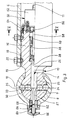
- Fig. 2 shows the left rear tilt bearing in a partially sectioned view from the rear.
- a carrier 6 extending in the transverse direction is fastened, on the two ends of which support heads 7 protrude.
- the support head 7 is spherical; it can also be designed in the form of a short cylinder, the axis of which extends in the longitudinal direction.
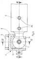
- An associated bearing housing 8 is fastened to the tipping bridge 2, which can be lowered onto the support head 7 and locked with it, leaving a rotational degree of freedom around the longitudinal axis 10 (FIG. 3).
- a sliding insert 12 is fastened, which encompasses the upper region of the support head 7 and has a damping effect and ensures a maintenance-free sliding pairing.
- the bearing housing 8 is open and its inner wall facing the carrier 6 has a cutout 14 through which the neck of the support head 7 can reach.
- the support head 7 has a rotational degree of freedom around the transverse axis 11 with respect to its support 6.
- the support 6 is a tube into which a cylindrical support body 16 formed integrally with the support head 7 can be rotated but is axially immovably inserted.
- the support head 7 and the support body 16 with the transition neck section located between them form the support head assembly 17.
- two slide ring inserts 18 are inserted, which ensure that the support body 16 is held in the carrier 6 in a maintenance-free manner.
- the axial immovability of the support body 16 is ensured in that two circumferential grooves 19 are incorporated in its cylindrical outer surface, each of which engages the front end of at least one form screw 20 which is screwed into a threaded hole of the carrier 6.
- the central channel 25 is crossed by a transverse bore 30 passing through the support head 7 in the direction of the longitudinal axis 10 of the tilt.
- a locking element 33 with rounded ends is seated on both sides of the expansion rod 26, in the present case in the form of two locking balls 34.
- the gradation of the expansion rod 26 ie the transition point between its front end 27 and rear end 28 lies in the region of the locking elements 33.
- a locking recess 35 in the form of a round pit is worked out at the points opposite the ends of the transverse bore 30, into which the outer ends of the locking elements 33 can engage.
- a compression spring 38 is inserted, the front end of which presses against a flange of the expansion rod 26 and attempts to press it into its front locking position, and the rear end of which is supported against a stop 39 fixed in the support body 16.
- a displacement drive 50 of the expansion rod 26 consists of an electromagnet 52 which is screwed onto the rear end of the support body 16 by means of an intermediate mounting plate 54 and whose armature 56 is connected to the expansion rod 26 via a pull rod 58.
- the electromagnet 52 When the electromagnet 52 is excited, it pulls the spreader rod into its rear release position against the action of the spring 38.
- a manually operated unlocking device 60 is located on the bearing housing 8 in the course of the transverse axis 11. It consists of a bushing 62 screwed into the bearing housing 8, in which a spring-loaded unlocking bolt 64 is actuated between two positions defined by a bayonet lock 68 by actuating a handle 66 and can be moved back and set in these.
- the described tilting bearing is in its locked state, in which the electromagnet 52 is without current and the spreader rod 26 is advanced under the action of the spring 38 into its locking position shown in FIG. 3, in which it moves the Latch balls 34 representing locking elements 33 presses outward, so that their outer ends engage in the locking recesses 35. In this way, the bearing housing is locked to the support head 7 and cannot be lifted off the latter.
- the tilt bridge 2 is firmly connected to the chassis 5.
- the electromagnets 52 of the two right tipping bearings are energized.
- the armature 56 is drawn into each of them and pulls the spreader rod 26 into its rear release position via the pull rod 58, in which its rear end 28 of large diameter migrates back from the region of the transverse bore 30.
- the bearing housing 8 can be lifted up off the support head 7.
- the electromagnets 52 of the two left tilt bearings are not energized, so that they remain locked. In this position, the bearing housing 8 only has a rotational degree of freedom around the longitudinal axis 10 relative to the support head 7.
- hydraulic fluid under pressure is supplied to the hydraulic cylinder between the chassis 5 and the tilting bridge 2 (not shown) and its extending piston rod pivots the tilting bridge with the platform box 3 about the left longitudinal tilting axis 10, as indicated by dashed lines in FIG. 1 on the left side.
- the rotational degree of freedom of the bearing housing 8 is used around the longitudinal axis 10, the sliding insert 12 sliding on the upper region of the support head 7.
- Tilting the tipping bridge to the right is analogous.
- the two front tilting bearings are brought into the release position by actuating their electromagnets 52, while the two rear tilting bearings remain locked.
- the application of the hydraulic cylinder between the chassis and the tipping bridge now leads to the tipping of the latter about the tipping transverse axis 11, the mutual position between the bearing housing 8 and the support head 7 remaining unchanged, but the rotational degree of freedom of the support head assembly 17 by that Tilt transverse axis 11 is used by the support body 16 rotates in the tube of the carrier 6.
- Both the four sliding drives 50, in the present case the electromagnet 52, and the hydraulic pump feeding the hydraulic cylinder are controlled in the driver's cab of the three-way tipper 1, four display means, e.g. Lamps are provided, which provide information about the locked state or the release position of the tilt bearing.
- a corresponding circuit only allows the combinations required for the three tilting options or the locking of all four tilting bearings.
- the tilting bearing can also be moved manually into the unlocking position, for which purpose the unlocking bolt 64 of the manual unlocking device 60 must be pressed in by actuating the handle 66 and locked in the pressed-in position by means of the bayonet lock 68, that is to say by a small rotation in the pressed-in position .
- the expansion rod 26 is also pushed back into its rear release position, so that the bearing housing 8 is released.
- the joint between the contacting front ends of the unlocking bolt 64 and the front end 27 of the spreader bar 26 must be flush with the separating surface between the bearing housing 8 and the support head 7. Then it can Bearing housing 8 are lifted from the support head 7.
- the front end 27 projecting when the electromagnet 52 is not activated can be pushed back by a ramp-like beveling of the bearing housing 8 or by another suitable measure.
Landscapes
- Engineering & Computer Science (AREA)
- Transportation (AREA)
- Mechanical Engineering (AREA)
- Ink Jet (AREA)
- Accommodation For Nursing Or Treatment Tables (AREA)
- Pivots And Pivotal Connections (AREA)
- Toys (AREA)
- Walking Sticks, Umbrellas, And Fans (AREA)
- Bridges Or Land Bridges (AREA)
Claims (10)
- Palier de basculement (4) déverrouillable pour le châssis basculant (2) d'une benne (1) pouvant basculer de trois côtés, caractérisé par
une tête d'appui (7) cylindrique ou sphérique qui peut tourner dans un support (6) solidaire du châssis de véhicule,
et un corps de palier (8) qui est fixé sur le châssis basculant (2) et peut être amené sur la tête d'appui, dont la surface intérieure supérieure lors de son déplacement vient en contact surfacique avec la surface supérieure de la tête d'appui (7), lequel corps de palier est ouvert vers le bas,
une tige de repoussement (26) étagée, mobile dans la direction longitudinale, étant montée dans un conduit central (25) de l'ensemble tête d'appui (17) et pouvant être déplacée au moyen d'un mécanisme d'entraînement (50) commandé à distance,
la tige de repoussement coopérant avec deux organes de verrouillage (33) montés de part et d'autre dans des perçages transversaux (30) avec possibilité de déplacement dans la direction de l'axe longitudinal (10) de basculement,
des cavités de verrouillage (35) étant aménagées en regard des perçages transversaux (30) dans les parois intérieures latérales du corps de palier (8), cavités dans lesquelles les extrémités extérieures des organes de verrouillage (33) pénètrent lorsque ceux-ci sont écartés par la tige de repoussement (26). - Palier de basculement selon la revendication 1, caractérisé par le fait que les extrémités des organes de verrouillage (33) sont arrondies.
- Palier de basculement selon la revendication 2, caractérisé par le fait que les organes de verrouillage (33) sont constitués chacun par deux billes de verrouillage (34) disposées l'une à côté de l'autre.
- Palier de basculement selon l'une ou plusieurs des revendications précédentes, caractérisé par le fait que l'extrémité antérieure (27) de la tige de repoussement (26) présente le diamètre le plus faible et est sollicitée par un ressort (38) dans le sens de sa sortie, l'extrémité arrière de la tige de repoussement étant liée à un électro-aimant (52) qui, lorsqu'il est actionné agit dans la direction de la rentrée de la tige.
- Palier de basculement selon l'une ou plusieurs des revendications précédentes destiné à être monté dans les deux angles arrières du châssis basculant, caractérisé par le fait que l'ensemble tête d'appui (17) est monté avec possibilité de rotation mais sans possibilité de déplacement dans la direction longitudinale dans le support (6) en forme de tube.
- Palier de basculement selon l'une ou plusieurs des revendications précédentes, caractérisé par le fait que le conduit central (25) de l'ensemble tête d'appui (17) est débouchant et qu'un dispositif de déverrouillage (60) actionné manuellement est monté dans la paroi en vis-à-vis du corps de palier (8), lequel dispositif de verrouillage présente un doigt de déverrouillage (64) qui coopère avec l'extrémité frontale antérieure de la tige de repoussement (26) et au moyen duquel la tige de repoussement (26) peut être repoussée dans sa position de déverrouillage à l'encontre de l'action du ressort (38), le point de contact entre le doigt de déverrouillage (64) et la tige de repoussement (26), en position de déverrouillage, étant situé dans le plan de séparation entre la paroi intérieure du corps de palier (8) et la surface en vis-à-vis de la tête d'appui (7).
- Palier de basculement selon la revendication 6, caractérisé par le fait que le doigt de déverrouillage (64) peut être bloqué dans la position provoquant le déverrouillage manuel au moyen d'un système de verrouillage (68) à baïonnette.
- Palier de basculement selon l'une ou plusieurs des revendications précédentes, caractérisé par un système de commande à distance de son mécanisme d'entraînement de la tige de repoussement agencé de manière telle que pour faire basculer le châssis basculant dans la direction souhaitée on libère les deux paliers concernés tandis que les deux autres paliers restent verrouillés.
- Palier de basculement selon la revendication 8, caractérisé par des moyens d'indication, en particulier par des voyants lumineux, destinés à indiquer l'état verrouillé ou l'état déverrouillé des quatre paliers de basculement de la benne basculante.
- Benne basculante pouvant basculer de trois côtés avec, disposés dans les quatre angles du châssis basculant, des paliers de basculement déverrouillables selon une ou plusieurs des revendications précédentes, caractérisé par un circuit de commande des paliers de basculement qui n'autorise que les trois combinaisons, vers la gauche, vers l'arrière ou vers la droite, nécessaires aux trois possibilités de basculement.
Priority Applications (3)
| Application Number | Priority Date | Filing Date | Title |
|---|---|---|---|
| AT90119965T ATE100381T1 (de) | 1990-10-18 | 1990-10-18 | Entriegelbares kipplager der kippbruecke eines dreiseitenkippers. |
| EP90119965A EP0481114B1 (fr) | 1990-10-18 | 1990-10-18 | Palier de basculement déverrouillable pour benne basculante d'un camion à triple mouvement de bascule |
| DE90119965T DE59004360D1 (de) | 1990-10-18 | 1990-10-18 | Entriegelbares Kipplager der Kippbrücke eines Dreiseitenkippers. |
Applications Claiming Priority (1)
| Application Number | Priority Date | Filing Date | Title |
|---|---|---|---|
| EP90119965A EP0481114B1 (fr) | 1990-10-18 | 1990-10-18 | Palier de basculement déverrouillable pour benne basculante d'un camion à triple mouvement de bascule |
Publications (2)
| Publication Number | Publication Date |
|---|---|
| EP0481114A1 EP0481114A1 (fr) | 1992-04-22 |
| EP0481114B1 true EP0481114B1 (fr) | 1994-01-19 |
Family
ID=8204626
Family Applications (1)
| Application Number | Title | Priority Date | Filing Date |
|---|---|---|---|
| EP90119965A Expired - Lifetime EP0481114B1 (fr) | 1990-10-18 | 1990-10-18 | Palier de basculement déverrouillable pour benne basculante d'un camion à triple mouvement de bascule |
Country Status (3)
| Country | Link |
|---|---|
| EP (1) | EP0481114B1 (fr) |
| AT (1) | ATE100381T1 (fr) |
| DE (1) | DE59004360D1 (fr) |
Families Citing this family (7)
| Publication number | Priority date | Publication date | Assignee | Title |
|---|---|---|---|---|
| ITBO20050291A1 (it) * | 2005-04-29 | 2006-10-30 | Hydro Metal S R L | Dispositivo per il bloccaggio di pianali ribaltabili di veicoli industriali e similari |
| PT104026B (pt) * | 2008-04-24 | 2010-03-09 | Ply Engenharia Lda | Caixa de carga modular multimateriais |
| ITMO20100033A1 (it) * | 2010-02-18 | 2011-08-19 | Italauto Car Sarl | Impianto per la selezione di un lato di ribaltamento di cassoni di veicoli da trasporto |
| IT201600095048A1 (it) * | 2016-09-22 | 2018-03-22 | Italauto Car Soc A Responsabilita Limitata | Dispositivo per il bloccaggio totale o selettivo di un cassone di un veicolo da trasporto |
| CN109534250B (zh) * | 2019-01-23 | 2023-12-29 | 廖凯轩 | 一种翻转平台 |
| CN111086859B (zh) * | 2020-01-08 | 2025-01-07 | 泰乐玛汽车制动系统(上海)有限公司 | 一种轴系总成翻转装置 |
| CN112644683B (zh) * | 2021-01-18 | 2023-09-26 | 国网新疆电力有限公司塔城供电公司 | 一种可自由拼装的无人机框架结构 |
Family Cites Families (3)
| Publication number | Priority date | Publication date | Assignee | Title |
|---|---|---|---|---|
| DE1844515U (de) * | 1961-10-21 | 1962-01-04 | Feka Fabrik Fuer Spezialfahrze | Feststellvorrichtung fuer zweiteilige kipplager an kippfahrzeugen und deren aufbauten. |
| GB1517993A (en) * | 1976-03-08 | 1978-07-19 | Tatra Np | Releasable fastening mechanisms for dump trucks |
| GB2106049A (en) * | 1981-08-05 | 1983-04-07 | Acoma | Threeway tipping vehicles |
-
1990
- 1990-10-18 EP EP90119965A patent/EP0481114B1/fr not_active Expired - Lifetime
- 1990-10-18 AT AT90119965T patent/ATE100381T1/de active
- 1990-10-18 DE DE90119965T patent/DE59004360D1/de not_active Expired - Fee Related
Also Published As
| Publication number | Publication date |
|---|---|
| DE59004360D1 (de) | 1994-03-03 |
| ATE100381T1 (de) | 1994-02-15 |
| EP0481114A1 (fr) | 1992-04-22 |
Similar Documents
| Publication | Publication Date | Title |
|---|---|---|
| DE68909886T2 (de) | Schwenkrampe mit automatischer Fahrzeugsperre. | |
| DE3930171A1 (de) | Fahrzeugsitz | |
| DE1296013B (de) | Hydraulischer Druckkolben | |
| DE4318945A1 (de) | Hydraulikkreis für ein Vier-Wege-Selektorventil mit geschlossener Mittenstellung | |
| EP1153875A1 (fr) | Unité de verrouillage et d'actionnement pour un dispositif de verrouillage latérale d'une flèche | |
| EP0481114B1 (fr) | Palier de basculement déverrouillable pour benne basculante d'un camion à triple mouvement de bascule | |
| DE3523280C2 (fr) | ||
| DE2658737A1 (de) | Spannvorrichtung, insbesondere greifer fuer kraene | |
| EP0490366A1 (fr) | Véhicule de transport avec conteneur interchangeable | |
| DE2921048C2 (de) | Betätigungsvorrichtung für ein oder jedes von mehreren nebeneinander angeordneten Ventilen | |
| DE60209396T2 (de) | Kuppelgestell für landwirtschaftliche Maschine | |
| DE202008008417U1 (de) | Verriegelung zum Verriegeln eines Containers auf einer Auflage | |
| DE2230048A1 (de) | Loesbarer verbinder fuer abkippbares fahrerhaus | |
| DE102017117655A1 (de) | Zweiradständer | |
| DE3913375C1 (fr) | ||
| DE3412167A1 (de) | Vorrichtung zum heben und kippen einer ladeflaeche | |
| DE2633022B1 (de) | Teleskopier-antriebs-einrichtung eines teleskopauslegers | |
| DE2106983A1 (de) | Teleskopierbarer Kranausleger | |
| DE1288984B (de) | Einstellbare Endabschaltung fuer die hydraulischen Hubzylinder einer zweiarmigen Ladeschwinge einer selbstfahrenden Arbeitsmaschine | |
| DE2841022A1 (de) | Arretiervorrichtung fuer ein verschwenkbares element, insbesondere fuer einen verschwenkbaren tragarm einer hebebuehne fuer kraftfahrzeuge | |
| DE3049507A1 (de) | Transportfahrzeug mit schiebeverriegelbarem wechselaufbau | |
| DE4412373A1 (de) | Schnellwechselsystem zur Befestigung eines Baggerwerkzeugs an einem Bagger | |
| EP0434906B1 (fr) | Fixation pendant le transport d'un réceptacle, par exemple un conteneur, une benne ou similaire. Ce réceptacle est amovible au moyen d'un dispositif interchangeable disposé sur le châssis du véhicule | |
| DE68907799T2 (de) | Hubvorrichtung. | |
| DE2343887C3 (de) | Einrichtung zur wahlweisen Fernoder Nahsteuerung der Arbeitszylinder eines hydraulisch betätigten Krans, insbesondere eines Mobilkrans |
Legal Events
| Date | Code | Title | Description |
|---|---|---|---|
| PUAI | Public reference made under article 153(3) epc to a published international application that has entered the european phase |
Free format text: ORIGINAL CODE: 0009012 |
|
| AK | Designated contracting states |
Kind code of ref document: A1 Designated state(s): AT BE CH DE DK ES FR GB GR IT LI LU NL SE |
|
| 17P | Request for examination filed |
Effective date: 19910823 |
|
| RAP1 | Party data changed (applicant data changed or rights of an application transferred) |
Owner name: HUNGER, WALTER, DR.-ING. |
|
| 17Q | First examination report despatched |
Effective date: 19930709 |
|
| GRAA | (expected) grant |
Free format text: ORIGINAL CODE: 0009210 |
|
| AK | Designated contracting states |
Kind code of ref document: B1 Designated state(s): AT BE CH DE DK ES FR GB GR IT LI LU NL SE |
|
| PG25 | Lapsed in a contracting state [announced via postgrant information from national office to epo] |
Ref country code: IT Free format text: LAPSE BECAUSE OF FAILURE TO SUBMIT A TRANSLATION OF THE DESCRIPTION OR TO PAY THE FEE WITHIN THE PRE;WARNING: LAPSES OF ITALIAN PATENTS WITH EFFECTIVE DATE BEFORE 2007 MAY HAVE OCCURRED AT ANY TIME BEFORE 2007. THE CORRECT EFFECTIVE DATE MAY BE DIFFERENT FROM THE ONE RECORDED.SCRIBED TIME-LIMIT Effective date: 19940119 Ref country code: FR Effective date: 19940119 Ref country code: GR Free format text: LAPSE BECAUSE OF FAILURE TO SUBMIT A TRANSLATION OF THE DESCRIPTION OR TO PAY THE FEE WITHIN THE PRESCRIBED TIME-LIMIT Effective date: 19940119 Ref country code: GB Effective date: 19940119 Ref country code: NL Effective date: 19940119 Ref country code: SE Effective date: 19940119 Ref country code: ES Free format text: THE PATENT HAS BEEN ANNULLED BY A DECISION OF A NATIONAL AUTHORITY Effective date: 19940119 Ref country code: DK Effective date: 19940119 Ref country code: BE Effective date: 19940119 |
|
| REF | Corresponds to: |
Ref document number: 100381 Country of ref document: AT Date of ref document: 19940215 Kind code of ref document: T |
|
| REF | Corresponds to: |
Ref document number: 59004360 Country of ref document: DE Date of ref document: 19940303 |
|
| EN | Fr: translation not filed | ||
| NLV1 | Nl: lapsed or annulled due to failure to fulfill the requirements of art. 29p and 29m of the patents act | ||
| GBV | Gb: ep patent (uk) treated as always having been void in accordance with gb section 77(7)/1977 [no translation filed] |
Effective date: 19940119 |
|
| PGFP | Annual fee paid to national office [announced via postgrant information from national office to epo] |
Ref country code: DE Payment date: 19941013 Year of fee payment: 5 |
|
| PG25 | Lapsed in a contracting state [announced via postgrant information from national office to epo] |
Ref country code: AT Effective date: 19941018 |
|
| PG25 | Lapsed in a contracting state [announced via postgrant information from national office to epo] |
Ref country code: LI Effective date: 19941031 Ref country code: LU Free format text: LAPSE BECAUSE OF NON-PAYMENT OF DUE FEES Effective date: 19941031 Ref country code: CH Effective date: 19941031 |
|
| PLBE | No opposition filed within time limit |
Free format text: ORIGINAL CODE: 0009261 |
|
| STAA | Information on the status of an ep patent application or granted ep patent |
Free format text: STATUS: NO OPPOSITION FILED WITHIN TIME LIMIT |
|
| 26N | No opposition filed | ||
| REG | Reference to a national code |
Ref country code: CH Ref legal event code: PL |
|
| PG25 | Lapsed in a contracting state [announced via postgrant information from national office to epo] |
Ref country code: DE Effective date: 19960702 |