EP0481131A1 - Tireuse par contact - Google Patents
Tireuse par contact Download PDFInfo
- Publication number
- EP0481131A1 EP0481131A1 EP90202790A EP90202790A EP0481131A1 EP 0481131 A1 EP0481131 A1 EP 0481131A1 EP 90202790 A EP90202790 A EP 90202790A EP 90202790 A EP90202790 A EP 90202790A EP 0481131 A1 EP0481131 A1 EP 0481131A1
- Authority
- EP
- European Patent Office
- Prior art keywords
- glass plate
- carriage
- radiation
- lamps
- exposure
- Prior art date
- Legal status (The legal status is an assumption and is not a legal conclusion. Google has not performed a legal analysis and makes no representation as to the accuracy of the status listed.)
- Withdrawn
Links
- 239000011521 glass Substances 0.000 claims abstract description 52
- 230000005855 radiation Effects 0.000 claims description 33
- 238000006073 displacement reaction Methods 0.000 claims description 2
- 239000000463 material Substances 0.000 claims description 2
- QSHDDOUJBYECFT-UHFFFAOYSA-N mercury Chemical compound [Hg] QSHDDOUJBYECFT-UHFFFAOYSA-N 0.000 abstract description 3
- 229910052753 mercury Inorganic materials 0.000 abstract description 3
- 210000004027 cell Anatomy 0.000 description 4
- 238000002508 contact lithography Methods 0.000 description 3
- 229910001507 metal halide Inorganic materials 0.000 description 3
- 150000005309 metal halides Chemical class 0.000 description 3
- 238000001816 cooling Methods 0.000 description 2
- 238000001312 dry etching Methods 0.000 description 2
- 230000000694 effects Effects 0.000 description 2
- 229910052751 metal Inorganic materials 0.000 description 2
- 239000002184 metal Substances 0.000 description 2
- 238000000034 method Methods 0.000 description 2
- 238000010521 absorption reaction Methods 0.000 description 1
- 210000002421 cell wall Anatomy 0.000 description 1
- 230000001413 cellular effect Effects 0.000 description 1
- CETPSERCERDGAM-UHFFFAOYSA-N ceric oxide Chemical compound O=[Ce]=O CETPSERCERDGAM-UHFFFAOYSA-N 0.000 description 1
- 239000004020 conductor Substances 0.000 description 1
- 239000000428 dust Substances 0.000 description 1
- 238000005265 energy consumption Methods 0.000 description 1
- 238000005286 illumination Methods 0.000 description 1
- 239000011022 opal Substances 0.000 description 1
- 239000002245 particle Substances 0.000 description 1
- 238000002360 preparation method Methods 0.000 description 1
- 238000009423 ventilation Methods 0.000 description 1
Images

Classifications
-
- G—PHYSICS
- G03—PHOTOGRAPHY; CINEMATOGRAPHY; ANALOGOUS TECHNIQUES USING WAVES OTHER THAN OPTICAL WAVES; ELECTROGRAPHY; HOLOGRAPHY
- G03B—APPARATUS OR ARRANGEMENTS FOR TAKING PHOTOGRAPHS OR FOR PROJECTING OR VIEWING THEM; APPARATUS OR ARRANGEMENTS EMPLOYING ANALOGOUS TECHNIQUES USING WAVES OTHER THAN OPTICAL WAVES; ACCESSORIES THEREFOR
- G03B27/00—Photographic printing apparatus
- G03B27/02—Exposure apparatus for contact printing
- G03B27/14—Details
- G03B27/16—Illumination arrangements, e.g. positioning of lamps, positioning of reflectors
Definitions
- Other known exposure apparatus comprise a plurality of tubular low-pressure mercury vapour fluorescent lamps, located close to the glass plate. A uniform illumination of the glass plate is obtained by the use of a diffusing screen between the lamps and the glass plate or by opal glass for the exposure plate.
- These apparatus are compact, but are not suited for carrying out the exposure of photographic film, being exposed to an original in the form of several superimposed sheets, as is the case in contact printing and dry retouching.
- the original may be a sandwich of a screen negative and positives, which is exposed to a direct-positive film to produce a colour-corrected reproduction.
- PRINTON DESC Trade name of AGFA-GEVAERT N.V., Mortsel, Belgium
- PRINTON DESC Trade name of AGFA-GEVAERT N.V., Mortsel, Belgium
- PRINTON Dry Etching System by Computer or in other words a computer-controlled working station for dry etching.
- the present specification is directed in particular to this technique, although it is not at all limited thereto.
- the exposure of a radiation-sensitive film to a sandwich of two or more superimposed sheets together forming an "original” requires the use of directed or so-called hard radiation in order to obtain in the film a sharp reproduction of the distinct images located in different planes.
- directed radiation means radiation that impinges on the glass plate supporting the sandwich of original and film at a normal or almost normal angle, e.g. with a deviation not larger than approximately 20 degrees.
- a contact exposure apparatus comprising a housing with a clear glass plate in one wall and means for holding a radiation-sensitive film and a transparent original in tight contact with each other on the outside surface of the glass plate and, inside the housing and facing the glass plate, an elongate displaceable lamp carriage covering the exposure width of the glass plate but only a part of the exposure length, the lamp carriage being movable along the length of the glass plate and having tubular low-pressure mercury vapour fluoresent lamps mounted side by side in a plane parallel to that of the glass plate and at a small distance from it and a honeycomb-like structure between the lamps and the glass plate, the axis of the cells of the structure being normal to the plane of the glass plate and at least the upper part of the walls of the cells absorbing the radiation of the lamps, and driving means for driving the carriage at a uniform speed along the length of the glass plate.
- the metal halide discharge lamps of known apparatus are kept energized at reduced power in standby. Considering that the effective exposure periods of the apparatus amount only to approximately 5 to 10 % of the total amount of working hours of the apparatus, it will be understood that the energy consumption of those known apparatus is high.
- width in the present specification means the dimension of the glass plate that runs parallel with the length of the lamp carriage, whereas the term “length” relates to the dimension that is normal thereto.
- honeycomb-like structure may cover the complete exposure area of the glass plate and remain stationary in the apparatus, it is far more interesting to use a structure of a size that nearly corresponds with the exposure opening of the light source and is fitted to the light source to integrally move with as it is moved along the length of the glass plate.
- the walls of the cells of the structure may be radiation absorbant over their full length, thereby producing very directed radiation. However, these walls may also be diffusely reflective at their end facing the lamps, so as to obtain a larger yield of the light source.
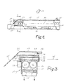
- the apparatus is mounted within a housing 11 having a clear glass exposure plate 12 in its top wall 13.
- An original and a radiation-sensitive film may be placed on the glass plate and held in tight contact with each other and with the glass plate by means of a blanket that is kept in rolled form in a blanket carriage 14, that in the present embodiment has a generally triangular cross-section.
- the rest position of the carriage is shown in solid lines, whereas the operative end position is illustrated in broken lines 15, the unrolled blanket being illustrated as 16.
- a bottom-light exposure apparatus comprising a blanket unrolling arrangement as described is commercially available under the reference CDL 2002 R, manufactured by AGFA-GEVAERT N.V., Mortsel, Belgium.
- a honeycomb plate 28 is fitted in a metal frame 29 which has a supporting sleeve 30 near each lateral end.
- the sleeves can axially slide over short supporting rods 31 and 32 having a bevelled free end, as is shown by the broken line 34 in fig. 3.
- the supporting rods are fitted to the inside of the inclined front wall 35 of the apparatus.
- the lamp carriage is provided at its rearside (considered according to the direction 36 of exposure by the carriage) with a solenoid 37 having a pawl 38 taking a position as illustrated when in rest, but is downwardly withdrawn when the solenoid is energized.
- the apparatus further comprises :
- the operation of the apparatus is as follows.
- the operator places a sandwich of an original and a daylight-type film on the glass plate of the apparatus and actuates a start button on the display panel 43 of the apparatus to start the exposure cycle.
- the blanket holder 14 is started and travels over the apparatus, thereby unrolling the blanket over the films lying on the glass plate. Then the vacuum pump is started and withdraws air whereby atmospheric pressure tightly urges the films in contact with each other.
- the walls 44 of the channels of the honeycomb plate 28 absorb any radiation that strikes their surface, so that the radiation leaving the plate has a directed configuration whereby a sharp reproduction of the image of the original on the radiation-sensitive film is obtained.
- the exposure is finished.
- the lamps can be extinguished and the vacuum released, so that the exposed film can be taken away for developing the latent image.
- solenoid 37 is energized and its pawl 38 is withdrawn, so that the honeycomb frame is not taken with the lamp carriage and the exposure of the radiation-sensitive film occurs by the radiation, omni-directionally emitted by the fluorescent lamps.
- honeycomb structure must not necessarily travel with the lamp carriage, but may also be supported separate therefrom.
- the honeycomb structure may have a size that corresponds approximately with that of glass plate. In such case it is advisable to provide means for causing the honceycomb structure to carry out small wobbling displacements in its own plane, thereby avoiding exposure of the cell walls on the film.
- the lamp carriage may have a mask over its opening that provides a compensation for radiation output variations of the lamps according to their length.
- the ventilation of the lamp carriage may be controlled to maintain the lamps at a temperature in the range of 40 ° to 45 ° C, which has been shown to offer a maximum radiation output for this type of lamps.
Landscapes
- Physics & Mathematics (AREA)
- General Physics & Mathematics (AREA)
- Silver Salt Photography Or Processing Solution Therefor (AREA)
- Exposure And Positioning Against Photoresist Photosensitive Materials (AREA)
Priority Applications (2)
| Application Number | Priority Date | Filing Date | Title |
|---|---|---|---|
| EP90202790A EP0481131A1 (fr) | 1990-10-19 | 1990-10-19 | Tireuse par contact |
| US07/774,189 US5262271A (en) | 1990-10-19 | 1991-10-10 | Negative silver salt diffusion transfer material |
Applications Claiming Priority (1)
| Application Number | Priority Date | Filing Date | Title |
|---|---|---|---|
| EP90202790A EP0481131A1 (fr) | 1990-10-19 | 1990-10-19 | Tireuse par contact |
Publications (1)
| Publication Number | Publication Date |
|---|---|
| EP0481131A1 true EP0481131A1 (fr) | 1992-04-22 |
Family
ID=8205149
Family Applications (1)
| Application Number | Title | Priority Date | Filing Date |
|---|---|---|---|
| EP90202790A Withdrawn EP0481131A1 (fr) | 1990-10-19 | 1990-10-19 | Tireuse par contact |
Country Status (2)
| Country | Link |
|---|---|
| US (1) | US5262271A (fr) |
| EP (1) | EP0481131A1 (fr) |
Families Citing this family (1)
| Publication number | Priority date | Publication date | Assignee | Title |
|---|---|---|---|---|
| GB9626281D0 (en) * | 1996-12-18 | 1997-02-05 | Kodak Ltd | Photographic high contrast silver halide material |
Citations (1)
| Publication number | Priority date | Publication date | Assignee | Title |
|---|---|---|---|---|
| US4962405A (en) * | 1989-11-17 | 1990-10-09 | Eastman Kodak Company | Compact contact printer with a flexible transparent cover sheet |
Family Cites Families (7)
| Publication number | Priority date | Publication date | Assignee | Title |
|---|---|---|---|---|
| US3672904A (en) * | 1970-05-01 | 1972-06-27 | Eastman Kodak Co | Photothermographic elements containing bis-beta-naphthols |
| IT1096437B (it) * | 1978-06-01 | 1985-08-26 | Breda Termomeccanica Spa | Apparecchiatura per la lavorazione automatica dei giunti in cilindri di grosso spessore |
| US4247617A (en) * | 1979-05-11 | 1981-01-27 | Polaroid Corporation | Silver diffusion transfer film unit transparency |
| JPS57186745A (en) * | 1981-05-13 | 1982-11-17 | Oriental Shashin Kogyo Kk | Manufacture of photosensitive silver halide and heat developable photosensitive material using said silver halide |
| US4693955A (en) * | 1984-03-19 | 1987-09-15 | Mitsubishi Paper Mills, Ltd. | Negative type lithographic printing plate |
| US4728596A (en) * | 1985-01-22 | 1988-03-01 | Fuji Photo Film Co., Ltd. | Light-sensitive element for silver salt diffusion transfer with iodine trapping layer |
| JPS62242947A (ja) * | 1986-04-15 | 1987-10-23 | Mitsubishi Paper Mills Ltd | 平版印刷版材料 |
-
1990
- 1990-10-19 EP EP90202790A patent/EP0481131A1/fr not_active Withdrawn
-
1991
- 1991-10-10 US US07/774,189 patent/US5262271A/en not_active Expired - Fee Related
Patent Citations (1)
| Publication number | Priority date | Publication date | Assignee | Title |
|---|---|---|---|---|
| US4962405A (en) * | 1989-11-17 | 1990-10-09 | Eastman Kodak Company | Compact contact printer with a flexible transparent cover sheet |
Also Published As
| Publication number | Publication date |
|---|---|
| US5262271A (en) | 1993-11-16 |
Similar Documents
| Publication | Publication Date | Title |
|---|---|---|
| US4229098A (en) | Photographic enlarger for producing giant-size prints | |
| US3208335A (en) | Photographic apparatus | |
| US5386268A (en) | Exposure unit and method for exposing photosensitive materials | |
| US3079839A (en) | Duplex photocopier | |
| US3240115A (en) | Photographic apparatus | |
| US4035074A (en) | Step and repeat camera having an improved film processor | |
| US3313225A (en) | Automatic multiple photoprinting system | |
| EP0481131A1 (fr) | Tireuse par contact | |
| US3498708A (en) | Photocopying apparatus | |
| US4488803A (en) | Slit exposure type copying camera | |
| US3169465A (en) | Contact printing apparatus | |
| US3509807A (en) | Photographic apparatus | |
| US3632204A (en) | Photoprinting and processing device | |
| US3437409A (en) | Photoprinting and processing device | |
| US3101024A (en) | All-purpose photographic mechanical reproduction camera | |
| US3834813A (en) | Diazo printing system | |
| US4987445A (en) | Scanning light contact duplicating apparatus | |
| US3517997A (en) | Document feeding and exposure means for an office copier | |
| US2895378A (en) | Photographic enlarger | |
| US3286608A (en) | Photographic-type printing device | |
| US3521951A (en) | Apparatus for exposure through a slit | |
| US3671124A (en) | Microfilm duplicator and method of photocopying microfilms | |
| US5649269A (en) | Image recording apparatus having a mask member moving together with an exposure unit | |
| US4711565A (en) | Add-on attachment for high-speed photographic printer | |
| US4257696A (en) | Photographic printing apparatus |
Legal Events
| Date | Code | Title | Description |
|---|---|---|---|
| PUAI | Public reference made under article 153(3) epc to a published international application that has entered the european phase |
Free format text: ORIGINAL CODE: 0009012 |
|
| AK | Designated contracting states |
Kind code of ref document: A1 Designated state(s): AT BE CH DE DK ES FR GB GR IT LI LU NL SE |
|
| RBV | Designated contracting states (corrected) |
Designated state(s): BE |
|
| REG | Reference to a national code |
Ref country code: DE Ref legal event code: 8566 |
|
| STAA | Information on the status of an ep patent application or granted ep patent |
Free format text: STATUS: THE APPLICATION IS DEEMED TO BE WITHDRAWN |
|
| 18D | Application deemed to be withdrawn |
Effective date: 19921023 |