EP0481139A1 - Entwässerungsverfahren - Google Patents
Entwässerungsverfahren Download PDFInfo
- Publication number
- EP0481139A1 EP0481139A1 EP90311414A EP90311414A EP0481139A1 EP 0481139 A1 EP0481139 A1 EP 0481139A1 EP 90311414 A EP90311414 A EP 90311414A EP 90311414 A EP90311414 A EP 90311414A EP 0481139 A1 EP0481139 A1 EP 0481139A1
- Authority
- EP
- European Patent Office
- Prior art keywords
- sludge
- belt
- plows
- mixing
- plow
- Prior art date
- Legal status (The legal status is an assumption and is not a legal conclusion. Google has not performed a legal analysis and makes no representation as to the accuracy of the status listed.)
- Granted
Links
- 238000000034 method Methods 0.000 title claims abstract description 17
- 230000008569 process Effects 0.000 title claims abstract description 17
- 239000010802 sludge Substances 0.000 claims abstract description 94
- 238000002156 mixing Methods 0.000 claims abstract description 26
- 239000007788 liquid Substances 0.000 claims description 19
- 230000003028 elevating effect Effects 0.000 claims description 9
- 238000000151 deposition Methods 0.000 claims 1
- 238000007599 discharging Methods 0.000 claims 1
- 230000002708 enhancing effect Effects 0.000 abstract description 2
- 239000007787 solid Substances 0.000 description 11
- 239000002002 slurry Substances 0.000 description 8
- XLYOFNOQVPJJNP-UHFFFAOYSA-N water Substances O XLYOFNOQVPJJNP-UHFFFAOYSA-N 0.000 description 6
- 230000005484 gravity Effects 0.000 description 4
- 239000000463 material Substances 0.000 description 4
- 238000011144 upstream manufacturing Methods 0.000 description 4
- 230000000712 assembly Effects 0.000 description 3
- 238000000429 assembly Methods 0.000 description 3
- 239000007791 liquid phase Substances 0.000 description 3
- 239000000203 mixture Substances 0.000 description 3
- 238000000926 separation method Methods 0.000 description 3
- 239000007790 solid phase Substances 0.000 description 3
- 230000004075 alteration Effects 0.000 description 2
- 238000004140 cleaning Methods 0.000 description 2
- 239000002657 fibrous material Substances 0.000 description 2
- 238000001914 filtration Methods 0.000 description 2
- 230000004048 modification Effects 0.000 description 2
- 238000012986 modification Methods 0.000 description 2
- 238000007790 scraping Methods 0.000 description 2
- 238000013019 agitation Methods 0.000 description 1
- 230000008859 change Effects 0.000 description 1
- 230000001419 dependent effect Effects 0.000 description 1
- 230000000694 effects Effects 0.000 description 1
- 239000012065 filter cake Substances 0.000 description 1
- 239000012071 phase Substances 0.000 description 1
- 230000008439 repair process Effects 0.000 description 1
- 230000000717 retained effect Effects 0.000 description 1
- 238000005096 rolling process Methods 0.000 description 1
- 230000032258 transport Effects 0.000 description 1
- 239000002699 waste material Substances 0.000 description 1
Images


Classifications
-
- B—PERFORMING OPERATIONS; TRANSPORTING
- B01—PHYSICAL OR CHEMICAL PROCESSES OR APPARATUS IN GENERAL
- B01D—SEPARATION
- B01D33/00—Filters with filtering elements which move during the filtering operation
- B01D33/04—Filters with filtering elements which move during the filtering operation with filtering bands or the like supported on cylinders which are impervious for filtering
-
- B—PERFORMING OPERATIONS; TRANSPORTING
- B01—PHYSICAL OR CHEMICAL PROCESSES OR APPARATUS IN GENERAL
- B01D—SEPARATION
- B01D33/00—Filters with filtering elements which move during the filtering operation
- B01D33/58—Handling the filter cake in the filter for purposes other than for regenerating the filter cake remaining on the filtering element
Definitions
- the present invention relates generally to the field of separating the liquid phase from the solid phase of a sludge or slurry.
- This separation is hereinafter referred to as "dewatering.”
- the sludge or slurry hereinafter jointly referred to as “sludge,” is deposited on and travels with a flight of an endless filter media with the liquid phase draining by gravity through the media and the solid phase traveling with the media to the point of discharge from the gravity dewatering part of the filtration equipment.
- this invention relates to a sludge dewatering system in which an array of sludge flow elevating devices ride at or on the surface of the filter media and cause the creation of multi-directional eddy mixing zones, i.e., currents of water and/or air running other than with the main currents, which greatly facilitate the separation of the liquid phase from the solid phase of the sludge.
- the invention disclosed herein advances the concepts and structure contained in these two patents, as well as other patents directed to plows or flow breakers, such as U.S. Patent No. 3,984,329, and greatly improves the capability of plows to facilitate the separation of liquid from a two-phase, solid-liquid mixture, or from a sludge that is being carried on a permeable filter belt.
- This is accomplished by creating a series of flow elevation zones with the creation of multidirectional eddy currents to imporve mixing over essentially the entire surface of the permeable filter belt that is in contact with the sludge.
- the solids-liquid mixture is caused to form a turbulent layer covering all or a large part of the filter belt surface which, because of the characteristics of the turbulent layer, greatly increase the rate of filtration, or drainage, of the liquid from the sludge.
- the process form of our invention is the more important aspect thereof. It comprises a process for dewatering sludge on a flight of a foraminous filter belt that moves longitudinally between sludge deposit and discharge positions.
- sludge is deposited on the flight, which is then moved in a longitudinal direction to a position where, initially, the sludge is elevated and mixed as it is carried by the belt. Thereafter, the sludge is again elevated and mixed on the belt, but to a greater extent than the initial elevation and mixing. Thereafter, the sludge is discharged from the belt flight.
- the sludge can undergo a third, and subsequent elevations and mixings; where there are three such elevations and mixings, each one will be to an extent greater than the preceding elevation and mixing.
- the sludge can be elevated and mixed to an extent such that it falls back upon itself to expose interior sludge portions.
- a plow assembly for elevating and mixing a body of sludge on a liquid permeable belt, which assembly includes a plow in the general form of a cone.
- the cone has a vertical axis and is located with the plane of the base of the cone at or in direct contact with the liquid permeable belt; the cone has a side wall extending upwardly and inwardly away from the belt.
- the plow is positioned on the belt so that as the flight of the belt moves past the plow, the sludge thereon will rise at least partially up the side wall of the conical plow, thereby elevating and disturbing the flow of the sludge, and agitating and mixing it to increase the flow of liquid from the sludge to the filter media, and then through the filter media to a location where it can be collected.
- the cone is a right circular cone.
- a row of conical plows extending across the width of the belt, preferably with their vertical axes in substantial alignment. It has also been found advantageous to have not simply one row of plows, but multiple rows of plows extending across the width of the filter media, for example, with the axes of the plows of one row being followed by a row with its axes in the gaps between the axes of the plows of the next row. In this manner a plurality of rows of plows can be arranged to form a cooperating group of plows in order still further to increase the extent of the flow elevation zones. Alternatively, rows of plows may simply be spaced along the length of the filter belt.
- a plow assembly that comprises at least two rows of plows spaced longitudinally along the length of the flight of the belt, with each plow being in the form of a cone the side walls of which slope to form an angle with the plane of the base of the plow.
- Cones of lesser slope i.e., cones having side walls which form a lesser angle with the plane of the base of the plow may be provided at upstream locations of the belt, by which term we refer to those portions of the belt nearer the point where sludge is discharged onto the media.
- the angle formed by the side wall and the base of the conical plows may be increased.
- Such increase results in more intense multi-directional eddy mixing being presented to the sludge, because as the solids concentration of the sludge has been increased, greater flow elevation and more intense mixing will be required to free additional liquid from the sludge mass.
- angles may be increased from 15° to 30 from upstream to downstream locations along the path of the filter media, and where groups of plows are utilized, the plows of each group can be formed with the same side wall slope in order to effect the desired concentration of the solids of the sludge.
- the present plow assembly comprises means for mounting a plow in the general form of a cone extending into the flow of sludge carried by a filter belt flight.
- the mounting means comprises a post extending horizontally across and above the path of movement of the belt, and a collar mounted on the post, which collar defines an elongated orifice the axis of which is substantially vertical when the plow is in flow elevating and multi-directional eddy mixing position.
- a shaft is positioned within the orifice of the collar and has a diameter slightly less than the diameter of the orifice, so that the shaft may rotate within the orifice and also move axially therewithin.
- a plow is mounted at the lower end of the shaft, so that in sludge-contacting position the plow depends substantially vertically from the collar and is at or in contact with the belt.
- the plow is preferably maintained in fixed position relative to the shaft, with a stop means provided at the top of the shaft above the orifice, to delimit downward movement of the shaft and plow.
- plow assemblies are mounted along the horizontal post, so that there are a series of collars extending transversely to the belt.
- the spacing of the collars is such that the conical plows are positioned closely adjacent to each other. In such position, sludge passing along the belt will be forced between and up the side walls of the plows, which are movable, in rotary and axial directions, in accordance with movement of the shaft. Further, the horizontal post and the plows carried by it are subject to vertical movement out of the path of the sludge on the belt.
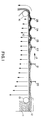
- a feed hopper 11 accumulates sludge 12 having a high liquid content. As sludges are measured in solids content, that content may typically be from one quarter to one percent (or more) solids.
- Flight 10 of the filter media is shown extending between rollers 15 and 16, which guide rollers rotate in a counter-clockwise direction so that the flight moves in the direction indicated by arrow 17. As guided by rollers 15 and 16, the flight 10 accumulates slurry or sludge 12 from feed hopper 11, which is deposited on the flight.
- the slurry then passes on the foraminous belt and, in the particular embodiment illustrated, contacts an upstream row of conical plows 20. Thereafter, the belt transports sludge to a second, more downstream row of plows 21, and thence, in sequence, to more downstream located rows 22, 23, 24 and 25. After passing by the row of plows 25, the sludge is then discharged into a suitable receptacle as the belt flight 10 passes about discharge roller 16 in a conventional manner.
- FIG. 3 The structure of an individual plow and the means by which the plow is mounted for operation are seen in a preferred mode in FIG. 3.
- Two plows are shown in FIG. 3, the plow 30 to the left being shown in side elevation and the plow 31 to the right being seen in vertical section.
- the elements of the plow and its mounting means comprise a horizontal post 33, which can be circular or square in cross-section, extends across the width of the belt, and is suitably mounted in side walls or other conventional structure located on either side of the belt flight 10.
- post 33 extends across the belt and the sludge carried on the belt, and carries support structure for maintaining the conical plows in position to dewater the slurry or sludge carried on the belt.
- a collar 34 is firmly fixed to the post 33.
- Collar 34 forms an interior, extended orifice 35.
- Extending within orifice 35 is a shaft 36 which terminates at one end in plow 38 and at the other end in a shaft head 39 that extends above the collar 34.
- shaft 36 There is a short length of shaft 36 between the top of the collar 34 and the bolt 39 to permit vertical movement of plow assembly 30.
- shaft 36 terminates downwardly in a nut 40 located above the conical plow 38 and a lock nut 41 that is located below the shell of the conical plow 38. In this manner, as mounted between nuts 40 and 41 at the lower end of shaft 36, the conical shell of plow 38 is firmly fixed on the shaft 36 so that the plow can only move in conjunction with shaft 36.
- shaft 36 has a diameter slightly less than the diameter of orifice 35 of collar 34, shaft 36 is free to rotate within collar 34. Further, shaft 36 is free to move in a generally vertical direction within the orifice 35. Motion in a downward direction by shaft 36 is limited by shaft head 39 affixed to the upper end of the shaft so that, for example, if the filter media 10 is removed for cleaning or repair, the plows 38 will move downward for a relatively short distance and will still be positioned so that on replacement of the filter media the plows will be in their proper position for dewatering sludge or slurry on the media.
- the plow assembly illustrated in FIG. 3, also includes an elongated sleeve that encloses the shaft 36.
- sleeve 37 In operative position sleeve 37 has its axis vertically disposed and is freely rotatable independently of any movement of the shaft 36.
- Use of such a sleeve acts to avoid hang-up of fibrous or other materials on shaft 36, since when there is any such tendency for material to adhere to shaft 36, the presence of a light rotatable sleeve will permit rotation and movement of the material past the sleeve and, therefore, the shaft.
- the side walls or shells of the plows of the present invention have a slope that forms an angle with plane of the base of the plow.
- base is used wherever the plow has a closed base or, as shown in the preferred embodiment, where the base of the plow is left open so that access may be had to the lock nut 41 in case it is desired to remove the plow.
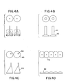
- FIG. 4 Shown herein in FIG. 4 in top plan and side elevations are several variants of cones that may be used in accordance with the present invention to elevate and mix sludge carried on a filter belt.
- FIG. 4A are cones having side walls that vary between slightly greater than 0 and approaching but less than 90 angles with the horizontal.
- FIG. 4B are plows where the frustum of a plow is then joined to a circular right cylinder, the cylinder being designated by numeral 41, mounted atop the frustum of circular right cone 42.
- FIG. 4C Shown in FIG. 4C are two general cones 45 with offset axes 46.
- FIG. 4D are shown a series of convoluted conical sections 49. Such sections are spaced closely together as shown in top plan view in FIG. 4D, and are not rotatable.
- a preferred embodiment of my invention is to employ in rows 20 and 21 plows that have a lower profile, i.e., plows the side walls of which form a lesser angle with the planes of their bases.
- the lower profile plows have an axis, i.e., maintain a distance of three-quarters of an inch between the base of the plow and the upward termination of the plow just below nut 40, which plow portion might be termed its frustum.
- that vertical dimension has been referred to be one-and-one- half inches.
- the low profile plows rows of which are located upstream in the direction of flow of sludge on the belt, have angles of approximately 15" with the horizontal; the higher profile plows located downstream in the path of movement of the belt have side walls that make angles of approximately 30 ° with the bases of the plows.
- the plows are mounted, all of the plows are free to float on the belt and, in preferred form, ride directly on the belt, perhaps separated by a thin layer of sludge that may adhere to the upper surface of the belt.
Landscapes
- Chemical & Material Sciences (AREA)
- Chemical Kinetics & Catalysis (AREA)
- Treatment Of Sludge (AREA)
- Filtration Of Liquid (AREA)
Priority Applications (2)
| Application Number | Priority Date | Filing Date | Title |
|---|---|---|---|
| AT90311414T ATE131741T1 (de) | 1990-10-17 | 1990-10-17 | Entwässerungsverfahren |
| DE1990624355 DE69024355T2 (de) | 1990-10-17 | 1990-10-17 | Entwässerungsverfahren |
Applications Claiming Priority (1)
| Application Number | Priority Date | Filing Date | Title |
|---|---|---|---|
| US07/382,279 US4986911A (en) | 1989-07-20 | 1989-07-20 | Dewatering process and apparatus |
Publications (2)
| Publication Number | Publication Date |
|---|---|
| EP0481139A1 true EP0481139A1 (de) | 1992-04-22 |
| EP0481139B1 EP0481139B1 (de) | 1995-12-20 |
Family
ID=23508269
Family Applications (1)
| Application Number | Title | Priority Date | Filing Date |
|---|---|---|---|
| EP90311414A Expired - Lifetime EP0481139B1 (de) | 1989-07-20 | 1990-10-17 | Entwässerungsverfahren |
Country Status (2)
| Country | Link |
|---|---|
| US (1) | US4986911A (de) |
| EP (1) | EP0481139B1 (de) |
Cited By (1)
| Publication number | Priority date | Publication date | Assignee | Title |
|---|---|---|---|---|
| US8092691B2 (en) | 2009-03-09 | 2012-01-10 | Univenture, Inc. | Method and apparatus for separating particles from a liquid |
Families Citing this family (9)
| Publication number | Priority date | Publication date | Assignee | Title |
|---|---|---|---|---|
| US5238584A (en) * | 1992-01-28 | 1993-08-24 | J. R. Schneider Co., Inc. | Apparatus for removing filtrate from filter media |
| US5560834A (en) * | 1995-04-06 | 1996-10-01 | Gold; Dennis D. | Machine for dewatering a slurry of ultrafine solids |
| US6053333A (en) * | 1995-10-06 | 2000-04-25 | Roediger Pittsburgh, Inc. | Method and system for transferring sludge, including a plow for dispersing sludge |
| AU4145897A (en) * | 1997-02-14 | 1998-09-08 | Warner-Jenkinson Company, Inc. | Method and apparatus for purifying water-insoluble compounds |
| US6871745B2 (en) * | 2002-12-20 | 2005-03-29 | John D. Lynn | Distributor apparatus for providing a uniform discharge of material |
| JP5777320B2 (ja) * | 2010-10-28 | 2015-09-09 | 株式会社クボタ | ベルト式ろ過装置 |
| NO340356B1 (en) * | 2015-09-04 | 2017-04-10 | Cubility As | Apparatus and method for separating liquid from a material comprising a solid fraction and a liquid fraction |
| WO2018049411A1 (en) * | 2016-09-12 | 2018-03-15 | Vermeer Manufacturing Company | Systems and methods for processing earthen slurries |
| US11084747B2 (en) * | 2019-09-24 | 2021-08-10 | Alfa Laval Corporate Ab | Dewatering apparatus, systems, and methods |
Citations (3)
| Publication number | Priority date | Publication date | Assignee | Title |
|---|---|---|---|---|
| US2097529A (en) * | 1934-12-20 | 1937-11-02 | Advance Engineering Company | Filter |
| US4879033A (en) * | 1988-08-26 | 1989-11-07 | Pilgrim's Pride Corporation | Slurry plow |
| FR2647028A1 (fr) * | 1989-05-18 | 1990-11-23 | Saulnier Michel | Dispositif d'egouttage d'une suspension solide-liquide |
Family Cites Families (7)
| Publication number | Priority date | Publication date | Assignee | Title |
|---|---|---|---|---|
| US465497A (en) * | 1891-12-22 | randall | ||
| NL176054C (nl) * | 1974-02-27 | 1985-02-18 | Bellmer Geb Kg Maschf | Filterinrichting. |
| GB2068760B (en) * | 1980-01-23 | 1984-02-01 | Hartley Simon Ltd | Apparatus for thickening sludge |
| US4602998A (en) * | 1985-06-27 | 1986-07-29 | Komline-Sanderson Engineering Corporation | Raisable plow assembly |
| US4609467A (en) * | 1985-08-07 | 1986-09-02 | Komline-Sanderson Engineering Corporation | Rotary plow assembly |
| US4729836A (en) * | 1986-12-01 | 1988-03-08 | Arus Andritz-Ruthner, Inc. | Flexible chicane system for liquid-solid separation equipment |
| US4857193A (en) * | 1987-06-01 | 1989-08-15 | Arus-Andritz Ruthner, Inc. | Floating chicane system for liquid-solid separation equipment |
-
1989
- 1989-07-20 US US07/382,279 patent/US4986911A/en not_active Expired - Fee Related
-
1990
- 1990-10-17 EP EP90311414A patent/EP0481139B1/de not_active Expired - Lifetime
Patent Citations (3)
| Publication number | Priority date | Publication date | Assignee | Title |
|---|---|---|---|---|
| US2097529A (en) * | 1934-12-20 | 1937-11-02 | Advance Engineering Company | Filter |
| US4879033A (en) * | 1988-08-26 | 1989-11-07 | Pilgrim's Pride Corporation | Slurry plow |
| FR2647028A1 (fr) * | 1989-05-18 | 1990-11-23 | Saulnier Michel | Dispositif d'egouttage d'une suspension solide-liquide |
Cited By (2)
| Publication number | Priority date | Publication date | Assignee | Title |
|---|---|---|---|---|
| US8092691B2 (en) | 2009-03-09 | 2012-01-10 | Univenture, Inc. | Method and apparatus for separating particles from a liquid |
| US8286801B2 (en) | 2009-03-09 | 2012-10-16 | Univenture, Inc. | Method and apparatus for separating particles from a liquid |
Also Published As
| Publication number | Publication date |
|---|---|
| EP0481139B1 (de) | 1995-12-20 |
| US4986911A (en) | 1991-01-22 |
Similar Documents
| Publication | Publication Date | Title |
|---|---|---|
| DE69410232T2 (de) | Trennung von flüssigen suspensionen | |
| US3923652A (en) | Method and apparatus for compacting fluid sludges | |
| DE2708340C3 (de) | Verfahren zur Filterung einer Schlämme oder Emulsion sowie Filtergerät zur Durchführung des Verfahrens | |
| DE2930581A1 (de) | Zentrifuge zum sortieren und trennen von feststoffen | |
| EP0166017B1 (de) | Vorrichtung zum Zerlegen von Mischstoffen | |
| US4986911A (en) | Dewatering process and apparatus | |
| DE3409826C2 (de) | ||
| KR19980702628A (ko) | 액체로부터 비용해 입자를 분리하기 위한 방법 및 장치 | |
| AT509457B1 (de) | Vorrichtung zum entwässern von granulat | |
| US5244583A (en) | Dewatering process | |
| EP1194383B1 (de) | Vorrichtung zum entwässern von schlamm | |
| US3454165A (en) | Apparatus for the separation of viscous components from a liquid | |
| JPH0336561B2 (de) | ||
| JPH0629679Y2 (ja) | 水砕鉱滓用のベルトコンベヤに鉱滓を均一投入する装置 | |
| CA2024780C (en) | Dewatering process and apparatus | |
| DE60012329T2 (de) | Verbesserte einspritzung von mit feststoffpartikeln beladenem wasser in einen zentrifugalabscheider | |
| DE69705615T2 (de) | Nassmahlverfahren und mühle zur durchführung des verfahrens | |
| JPH0776871A (ja) | 分離物を液体から除去するための装置 | |
| DE19801733C2 (de) | Verfahren und Vorrichtung zur Trennung von Abwasser mit bioorganischer Schmutzfracht in Feststoffe und die einzelnen Flüssigkeiten | |
| DE2165657A1 (de) | Vorrichtung zum Konzentrieren von in einer Flüssigkeit vorhandenen Feststoffen | |
| EP0621076B1 (de) | Verfahren zur Abtrennung von Feststoffen | |
| EP1134323A2 (de) | Sandfanganlage | |
| DE2303212C2 (de) | Austragsvorrichtung für Granulierwirbelschichtapparate | |
| KR102362382B1 (ko) | 협잡물 여과 및 모래탈수 효과가 증진된 협잡물처리기 | |
| DE2817860C2 (de) | Scheibenvakuumfilter |
Legal Events
| Date | Code | Title | Description |
|---|---|---|---|
| PUAI | Public reference made under article 153(3) epc to a published international application that has entered the european phase |
Free format text: ORIGINAL CODE: 0009012 |
|
| AK | Designated contracting states |
Kind code of ref document: A1 Designated state(s): AT BE CH DE ES FR GB IT LI LU NL SE |
|
| 17P | Request for examination filed |
Effective date: 19921020 |
|
| 17Q | First examination report despatched |
Effective date: 19930817 |
|
| GRAA | (expected) grant |
Free format text: ORIGINAL CODE: 0009210 |
|
| AK | Designated contracting states |
Kind code of ref document: B1 Designated state(s): AT BE CH DE ES FR GB IT LI LU NL SE |
|
| PG25 | Lapsed in a contracting state [announced via postgrant information from national office to epo] |
Ref country code: IT Free format text: LAPSE BECAUSE OF FAILURE TO SUBMIT A TRANSLATION OF THE DESCRIPTION OR TO PAY THE FEE WITHIN THE PRE;WARNING: LAPSES OF ITALIAN PATENTS WITH EFFECTIVE DATE BEFORE 2007 MAY HAVE OCCURRED AT ANY TIME BEFORE 2007. THE CORRECT EFFECTIVE DATE MAY BE DIFFERENT FROM THE ONE RECORDED.SCRIBED TIME-LIMIT Effective date: 19951220 Ref country code: FR Effective date: 19951220 Ref country code: AT Effective date: 19951220 Ref country code: ES Free format text: THE PATENT HAS BEEN ANNULLED BY A DECISION OF A NATIONAL AUTHORITY Effective date: 19951220 Ref country code: NL Free format text: LAPSE BECAUSE OF FAILURE TO SUBMIT A TRANSLATION OF THE DESCRIPTION OR TO PAY THE FEE WITHIN THE PRESCRIBED TIME-LIMIT Effective date: 19951220 Ref country code: BE Effective date: 19951220 Ref country code: LI Effective date: 19951220 Ref country code: CH Effective date: 19951220 |
|
| REF | Corresponds to: |
Ref document number: 131741 Country of ref document: AT Date of ref document: 19960115 Kind code of ref document: T |
|
| REF | Corresponds to: |
Ref document number: 69024355 Country of ref document: DE Date of ref document: 19960201 |
|
| PG25 | Lapsed in a contracting state [announced via postgrant information from national office to epo] |
Ref country code: SE Effective date: 19960320 |
|
| EN | Fr: translation not filed | ||
| NLV1 | Nl: lapsed or annulled due to failure to fulfill the requirements of art. 29p and 29m of the patents act | ||
| PLBE | No opposition filed within time limit |
Free format text: ORIGINAL CODE: 0009261 |
|
| STAA | Information on the status of an ep patent application or granted ep patent |
Free format text: STATUS: NO OPPOSITION FILED WITHIN TIME LIMIT |
|
| PG25 | Lapsed in a contracting state [announced via postgrant information from national office to epo] |
Ref country code: LU Free format text: LAPSE BECAUSE OF NON-PAYMENT OF DUE FEES Effective date: 19961031 |
|
| 26N | No opposition filed | ||
| PGFP | Annual fee paid to national office [announced via postgrant information from national office to epo] |
Ref country code: GB Payment date: 20001011 Year of fee payment: 11 |
|
| PGFP | Annual fee paid to national office [announced via postgrant information from national office to epo] |
Ref country code: DE Payment date: 20001023 Year of fee payment: 11 |
|
| PG25 | Lapsed in a contracting state [announced via postgrant information from national office to epo] |
Ref country code: GB Free format text: LAPSE BECAUSE OF NON-PAYMENT OF DUE FEES Effective date: 20011017 |
|
| REG | Reference to a national code |
Ref country code: GB Ref legal event code: IF02 |
|
| GBPC | Gb: european patent ceased through non-payment of renewal fee |
Effective date: 20011017 |
|
| PG25 | Lapsed in a contracting state [announced via postgrant information from national office to epo] |
Ref country code: DE Free format text: LAPSE BECAUSE OF NON-PAYMENT OF DUE FEES Effective date: 20020702 |