EP0481144A1 - Support-amortisseur télescopique - Google Patents
Support-amortisseur télescopique Download PDFInfo
- Publication number
- EP0481144A1 EP0481144A1 EP90311520A EP90311520A EP0481144A1 EP 0481144 A1 EP0481144 A1 EP 0481144A1 EP 90311520 A EP90311520 A EP 90311520A EP 90311520 A EP90311520 A EP 90311520A EP 0481144 A1 EP0481144 A1 EP 0481144A1
- Authority
- EP
- European Patent Office
- Prior art keywords
- casing
- members
- elastomeric
- motion
- ribbed
- Prior art date
- Legal status (The legal status is an assumption and is not a legal conclusion. Google has not performed a legal analysis and makes no representation as to the accuracy of the status listed.)
- Granted
Links
- 230000033001 locomotion Effects 0.000 claims abstract description 51
- 230000006835 compression Effects 0.000 claims abstract description 8
- 238000007906 compression Methods 0.000 claims abstract description 8
- 238000010276 construction Methods 0.000 claims description 5
- 230000001965 increasing effect Effects 0.000 claims description 4
- 230000009471 action Effects 0.000 claims description 3
- 238000010521 absorption reaction Methods 0.000 claims description 2
- 238000013016 damping Methods 0.000 description 17
- 239000013536 elastomeric material Substances 0.000 description 12
- 229910052751 metal Inorganic materials 0.000 description 6
- 239000002184 metal Substances 0.000 description 6
- 238000004519 manufacturing process Methods 0.000 description 5
- 125000006850 spacer group Chemical group 0.000 description 5
- 230000008878 coupling Effects 0.000 description 4
- 238000010168 coupling process Methods 0.000 description 4
- 238000005859 coupling reaction Methods 0.000 description 4
- 239000000463 material Substances 0.000 description 4
- 239000000203 mixture Substances 0.000 description 3
- 230000002093 peripheral effect Effects 0.000 description 3
- 230000004044 response Effects 0.000 description 3
- 229910000831 Steel Inorganic materials 0.000 description 2
- 230000001133 acceleration Effects 0.000 description 2
- 230000004308 accommodation Effects 0.000 description 2
- 239000010959 steel Substances 0.000 description 2
- 238000003466 welding Methods 0.000 description 2
- 239000004677 Nylon Substances 0.000 description 1
- 239000000853 adhesive Substances 0.000 description 1
- 230000001070 adhesive effect Effects 0.000 description 1
- 230000004075 alteration Effects 0.000 description 1
- 229910052782 aluminium Inorganic materials 0.000 description 1
- XAGFODPZIPBFFR-UHFFFAOYSA-N aluminium Chemical compound [Al] XAGFODPZIPBFFR-UHFFFAOYSA-N 0.000 description 1
- 230000000712 assembly Effects 0.000 description 1
- 238000000429 assembly Methods 0.000 description 1
- 230000005540 biological transmission Effects 0.000 description 1
- 230000006866 deterioration Effects 0.000 description 1
- 238000004512 die casting Methods 0.000 description 1
- 238000006073 displacement reaction Methods 0.000 description 1
- 230000000694 effects Effects 0.000 description 1
- 238000005516 engineering process Methods 0.000 description 1
- 239000012530 fluid Substances 0.000 description 1
- 239000004519 grease Substances 0.000 description 1
- 230000006872 improvement Effects 0.000 description 1
- 230000001939 inductive effect Effects 0.000 description 1
- 238000001746 injection moulding Methods 0.000 description 1
- 238000009434 installation Methods 0.000 description 1
- 239000000314 lubricant Substances 0.000 description 1
- 239000003879 lubricant additive Substances 0.000 description 1
- 230000013011 mating Effects 0.000 description 1
- 230000007246 mechanism Effects 0.000 description 1
- 238000000034 method Methods 0.000 description 1
- 230000004048 modification Effects 0.000 description 1
- 238000012986 modification Methods 0.000 description 1
- 229920001778 nylon Polymers 0.000 description 1
- 230000010355 oscillation Effects 0.000 description 1
- 229920001296 polysiloxane Polymers 0.000 description 1
- 230000035945 sensitivity Effects 0.000 description 1
- 239000007787 solid Substances 0.000 description 1
- 230000003068 static effect Effects 0.000 description 1
- 238000006467 substitution reaction Methods 0.000 description 1
- 239000000725 suspension Substances 0.000 description 1
- BFKJFAAPBSQJPD-UHFFFAOYSA-N tetrafluoroethene Chemical group FC(F)=C(F)F BFKJFAAPBSQJPD-UHFFFAOYSA-N 0.000 description 1
- 238000009424 underpinning Methods 0.000 description 1
Images


Classifications
-
- F—MECHANICAL ENGINEERING; LIGHTING; HEATING; WEAPONS; BLASTING
- F16—ENGINEERING ELEMENTS AND UNITS; GENERAL MEASURES FOR PRODUCING AND MAINTAINING EFFECTIVE FUNCTIONING OF MACHINES OR INSTALLATIONS; THERMAL INSULATION IN GENERAL
- F16F—SPRINGS; SHOCK-ABSORBERS; MEANS FOR DAMPING VIBRATION
- F16F7/00—Vibration-dampers; Shock-absorbers
- F16F7/08—Vibration-dampers; Shock-absorbers with friction surfaces rectilinearly movable along each other
- F16F7/09—Vibration-dampers; Shock-absorbers with friction surfaces rectilinearly movable along each other in dampers of the cylinder-and-piston type
-
- B—PERFORMING OPERATIONS; TRANSPORTING
- B60—VEHICLES IN GENERAL
- B60K—ARRANGEMENT OR MOUNTING OF PROPULSION UNITS OR OF TRANSMISSIONS IN VEHICLES; ARRANGEMENT OR MOUNTING OF PLURAL DIVERSE PRIME-MOVERS IN VEHICLES; AUXILIARY DRIVES FOR VEHICLES; INSTRUMENTATION OR DASHBOARDS FOR VEHICLES; ARRANGEMENTS IN CONNECTION WITH COOLING, AIR INTAKE, GAS EXHAUST OR FUEL SUPPLY OF PROPULSION UNITS IN VEHICLES
- B60K5/00—Arrangement or mounting of internal-combustion or jet-propulsion units
- B60K5/12—Arrangement of engine supports
- B60K5/1241—Link-type support
-
- B—PERFORMING OPERATIONS; TRANSPORTING
- B60—VEHICLES IN GENERAL
- B60K—ARRANGEMENT OR MOUNTING OF PROPULSION UNITS OR OF TRANSMISSIONS IN VEHICLES; ARRANGEMENT OR MOUNTING OF PLURAL DIVERSE PRIME-MOVERS IN VEHICLES; AUXILIARY DRIVES FOR VEHICLES; INSTRUMENTATION OR DASHBOARDS FOR VEHICLES; ARRANGEMENTS IN CONNECTION WITH COOLING, AIR INTAKE, GAS EXHAUST OR FUEL SUPPLY OF PROPULSION UNITS IN VEHICLES
- B60K5/00—Arrangement or mounting of internal-combustion or jet-propulsion units
- B60K5/12—Arrangement of engine supports
- B60K5/1266—Supports comprising friction damping devices
-
- F—MECHANICAL ENGINEERING; LIGHTING; HEATING; WEAPONS; BLASTING
- F16—ENGINEERING ELEMENTS AND UNITS; GENERAL MEASURES FOR PRODUCING AND MAINTAINING EFFECTIVE FUNCTIONING OF MACHINES OR INSTALLATIONS; THERMAL INSULATION IN GENERAL
- F16F—SPRINGS; SHOCK-ABSORBERS; MEANS FOR DAMPING VIBRATION
- F16F13/00—Units comprising springs of the non-fluid type as well as vibration-dampers, shock-absorbers, or fluid springs
- F16F13/04—Units comprising springs of the non-fluid type as well as vibration-dampers, shock-absorbers, or fluid springs comprising both a plastics spring and a damper, e.g. a friction damper
-
- F—MECHANICAL ENGINEERING; LIGHTING; HEATING; WEAPONS; BLASTING
- F16—ENGINEERING ELEMENTS AND UNITS; GENERAL MEASURES FOR PRODUCING AND MAINTAINING EFFECTIVE FUNCTIONING OF MACHINES OR INSTALLATIONS; THERMAL INSULATION IN GENERAL
- F16F—SPRINGS; SHOCK-ABSORBERS; MEANS FOR DAMPING VIBRATION
- F16F3/00—Spring units consisting of several springs, e.g. for obtaining a desired spring characteristic
- F16F3/08—Spring units consisting of several springs, e.g. for obtaining a desired spring characteristic with springs made of a material having high internal friction, e.g. rubber
- F16F3/087—Units comprising several springs made of plastics or the like material
-
- F—MECHANICAL ENGINEERING; LIGHTING; HEATING; WEAPONS; BLASTING
- F16—ENGINEERING ELEMENTS AND UNITS; GENERAL MEASURES FOR PRODUCING AND MAINTAINING EFFECTIVE FUNCTIONING OF MACHINES OR INSTALLATIONS; THERMAL INSULATION IN GENERAL
- F16C—SHAFTS; FLEXIBLE SHAFTS; ELEMENTS OR CRANKSHAFT MECHANISMS; ROTARY BODIES OTHER THAN GEARING ELEMENTS; BEARINGS
- F16C7/00—Connecting-rods or like links pivoted at both ends; Construction of connecting-rod heads
- F16C7/04—Connecting-rods or like links pivoted at both ends; Construction of connecting-rod heads with elastic intermediate part of fluid cushion
Definitions
- the present invention relates to elements for providing a damped tension and compression connection between spaced objects, and more particularly the present invention relates to motion-damping torque struts such as find particular utility in vehicles to counter engine torque.
- the engine In many front wheel drive automobiles currently on the market, the engine is mounted transversely in the engine compartment and is customarily supported on mounts and connected to a frame component of the automobile by means of a so-called torque strut.
- the torque strut functions to control angular displacement of the engine, such as when output torque increases during acceleration, and during braking, while accommodating normal engine oscillations, such as when the engine is operating at idle.
- Known torque struts include an elongate member mounting at opposite ends a pair of sleeved rubber bushings for receiving a connecting bolt. While such struts have been capable of performing the aforedescribed functions, they have certain limitations. For instance, the rubber bushings at the ends of the struts are prone to deterioration due to large motions across the bushings while subjected to the heat of the engine so that, after a period of time, the bushings crack and stiffen. As a result, the struts develop a proclivity for transmitting vibrations and noises to the frame and hence into the passenger compartment, particularly during acceleration of the automobile when the strut is subjected to substantial tensile loads.
- a strut representing an improvement over the aforementioned struts is disclosed in U.S. Patent No. 4,706,946 issued to Lord Corporation, the assignee of the present application. It incorporates friction elements to provide a friction damping action.
- the present invention provides a novel strut assembly which is particularly suited for providing both a tension and a compression connection between relatively movable objects while simultaneously providing motion damping.
- the present invention also provides an improved torque strut which utilizes both friction and elastomeric hysteresis to provide the desired degree of motion damping.
- the invention provides a unique torque strut which overcomes the limitations of knock torque struts by providing a desired amount of motion accommodation and damping without causing harsh snubbing action.
- the present invention provides a torque strut which is designed in such a manner as to enable different design requirements to be accommodated readily, which is reliable and rugged, and which can be manufactured efficiently utilizing known manufacturing technologies.
- the present invention provides a strut assembly for use in forming a motion- damped tension and compression connection between first and second relatively movable objects.
- the strut assembly comprises an elongate casing which is adapted to be disposed on an axis extending between the objects.
- First and second axially- spaced members are mounted in the casing and are adapted to be connected to the first and second objects respectively. At least the first member is movable relative to the casing.
- Intermediate elastomeric means is provided between the members for limiting motion toward one another in the axial direction, and terminal elastomeric means is provided in the casing for limiting motion of the members away from one another in the axial direction.
- Frictional and hysteresis motion damping is provided by an elastomeric layer which is contained in the casing alongside the axis and which cooperates with ribbed means carried in the casing in pressure engagement with the layer.
- the ribbed means is displaced relative to the elastomeric layer in response to motion of at least the first member relative to the casing for slidably deforming said elastomeric layer whereby relative motion can be damped in opposite axial directions.
- a lost motion connection is provided between at least one of the members and its associated ribbed means for enabling the member to move a predetermined distance relative to the elastomeric layer without effecting a corresponding amount of motion of the ribbed means.
- the terminal elastomeric means is shaped to deform and provide energy absorption which increases with increased motion.
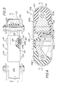
- FIG. 1 illustrates one embodiment of a strut assembly 10 constructed in accordance with the present invention.
- the strut assembly 10 is adapted to connect spaced relatively movable objects, such as the pair of spaced relatively movable brackets 11 a, 11 and 12a, 12b.
- the strut assembly 10 is elongated on an axis A extending between the brackets 11 a, 11 b and 12a, 12b which may be components of a vehicle, such as an engine and a body or frame component.
- the strut assembly 10 can limit effectively the tendency of the engine to move relative to the vehicle by reacting either tensile or compressive forces applied on the axis A.
- the strut assembly 10 comprises two substantially identical strut sections 10a and 10b which are joined together along a medial plane P orthogonal to the longitudinal axis A.
- the right-hand casing section 10a comprises a formed metal shell 13 having a semicircular terminal strap- like end portion 13a and a medial box-like portion 13b defined by upturned and downturned pairs of flanges 13c, 13d, 13e, 13f, forming confronting channels joined along a horizontal plane.
- the flanges 13e - 13f are relieved adjacent opposite ends of the strut assembly at 13', 13" to provide mounting clearances.
- the companion strut section 10b likewise includes a metal shell 14 which is shaped similar to the shell 13 but which has crimped flange portions 14b embracing an outturned flanges 13g of its companion shell 13 to form a secure transverse interlock along the medial plane P.
- the shells 13 and 14 are rectangular in transverse cross section and have hollow elongate centrally located interior chambers Ci, C 2 .
- the interlocked shell sections 13 and 14 cooperate to form a unitary strut casing 10 which, as will be described, can accept tensile forces applied on the axis A.
- a pair of connecting members 16 and 17 are mounted in the casing chambers Ci, C 2 for movement relative to their respective strut sections 10a and 10b, and for movement relative to one another in the chambers C 1 , C 2 .
- both connecting members 16 and 17 are of identical construction, but there may be installations which might require them to be different.
- the first connecting member 16 has a terminal lug end portion 16e with a through bore 16' which is adapted to receive a fastener, such as the bolt 18, spanning across the member 16 and the brackets 11 a, 11 b.
- spacers 19 and 20 (FIG.
- the companion, or second, connecting member 17 has a terminal lug end with a similar through bore 17' which is parallel to the bore 16' and which is connected by a bolt 21 and spacers 22 and 23 to the brackets 12a, 12b.
- the right-hand connecting member 16 has a main body portion which is preferably of die cast metal, such as aluminum.
- the connecting member 16 has a rectangular recess 16a which opens toward the medial plane P and which is defined by a continuous flange 16b having a peripheral groove 16c.
- the connecting member 16 has a pair of tapered surfaces 16d, 16d ,which converge toward the axis A from the region of the peripheral groove 16c toward the lug portion 16e in which the bore 16' is formed.
- the connecting member 16 is completely surrounded by a molded mass of elastomeric material 20 provided in the shell 13.
- the elastomeric material 20 has a terminal end portion 20a which is recessed to receive the lug portion 16e of the connecting member 16 and which has a box-like wall portion 20b extending from the terminal end portion 20a to the medial plane P.
- the wall portion 20b surrounds the peripheral flange 16b of the connecting member 16 in spaced relation.
- the elastomeric material 20 is shaped to engage the inner surface of the shell 13 and may be, and preferably is, bonded thereto.
- the terminal end portion 20a of the elastomeric material 20 has a pair of protrusions 20c, 20c which project inwardly from the casing 13 transversely of the axis A to provide shoulders that engage the tapered surfaces 16d, 16d of the connecting member 16 in the manner illustrated in FIG. 2 when the strut assembly 10 is in its normal at-rest position.
- the terminal end portion 20a of the elastomeric material 20 is suitably recessed around the lug 16e in the manner illustrated to provide space for accommodating deflection of the protrusions 20c, 20c as the connecting member 16 moves axially rightward in use.
- the shouldered protrusions 20c, 20c of the elastomeric mass 20 engage the tapered surfaces 16d, 16d of the connecting member 16 over increasing areas as the connecting member 16 moves axially rightward, thereby created increasing frictional forces which aid in gently arresting axial rightward movement of the connecting member 16.
- Extreme rightward excursions of the connecting member 16 are completely arrested by an axial elastomeric abutment 20d formed in the elastomeric mass 20 and located in the path of movement of the lug 16e.
- a block of elastomeric material 22 is provided in the casing chamber Ci.
- the elastomeric block 22 has a protrusion 22a which is received within the recess 16a of the connecting member 16 and a base 22b extending outwardly from the protrusion 22a across the ends of the connecting member flange 16b.
- An identical block of elastomeric material 23 abuts the block 22 along the medial plane P and is similarly disposed with respect to the connecting member 17.
- the blocks 22 and 23 provide a centrally-located cushion which deforms in compression in response to axial inward motion of the connecting members 16 and 17, thereby absorbing energy imparted in that direction and limiting axial inward motion of the connecting members.
- ribbed means is mounted in the chamber C, for movement relative to the elastomeric mass 20 in response to motion of the connecting member 16.
- the ribbed means includes a collar-like slide element 25 carried on the connecting member 16 and mounted in its groove 16c.
- the ribbed slide element 25 has a plurality of contoured ribs, such as the pair of continuous, spaced, parallel, smoothly contoured ribs 25a, 25b formed in its outer periphery and disposed in pressure engagement with the elastomeric layer 20b which surrounds it.
- the slide element 25 has a predetermined widthwise dimension, i.e. dimension parallel to the axis A. If desired, it may be dimensioned to completely occupy the axial extent of the groove 16c in the connecting member 16, in which event it is directly coupled to the connecting member 16 so that all axial motion of the connecting member 16 causes the slide element 25 to move along the elastomeric layer 20b. Also, because of the rectangular shape cocking motions of the member 16, such as vertically arcuate in FIG. 1 and horizontally arcuate in FIG. 2, result in damping of undesirable rotational motions in engine suspensions.
- a lost motion connection is provided between the slide element 25 and the connecting member 16.
- the lost motion connection is provided by causing the slide element 25 to have a slightly narrower widthwise dimension than the widthwise dimension of the groove 16c and by causing it to have a coefficient of sliding friction relative to the connecting member 16 which is lower than the coefficient of sliding friction between it and its juxtaposed elastomeric layer 20b.
- the widthwise dimension of the groove 16c is in a range of about 0.010 to 0.080 inches greater than the widthwise dimension of the slide element 25.
- the material of which the slide element 25 is composed is important. It should have a ratio of static to dynamic, or sliding, coefficients of friction of approximately unity, with a relatively high coefficient relative to the elastomeric layer and a relatively low coefficient with respect to the material of which the connecting member 16 is composed.
- polymeric compositions of reinforced nylon having up to about 20%, by weight, tetrafluoroethylene and about 2%, by weight of silicone lubricant additives are desirable for the slide element 25.
- Such a composition eliminates the need for a lubricant, such as a grease.
- the coefficient of relative sliding friction between the ribbed outer surface 25a, 25b of the slide element 25 and its juxtaposed elastomeric layer 20c should be in a range of about 0.2 to about 2.0, and the corresponding coefficient of relative sliding friction between the inner surface of the slide element 25 and the bottom of the groove 16c of the connecting member 16 should be in a range of about 0.01 to about 0.1.
- Precompression of the elastomeric layer 20c by the ribs 25a, 25b should be in a range of about 5% to about 30% of its thickness in the direction of applied compression.
- Each strut section 10a and 10b is provided with the elastomeric material bonded therein.
- a slide element 25 is slid into place onto its associated connecting member by slipping it axially into its receiving groove from the lug end of the connecting member.
- the connecting members 16 and 17 are inserted, lug ends first, into their respective receiving chambers C 1 , C 2 .
- the elastomeric blocks 22 and 23 are then mounted in their receiving recesses in the connecting members 16 and 17 respectively, and the shells 13 and 14 are placed in a press in which their medial flanges are crimped together in the manner illustrated.
- the spacers 19 and 20 may be supplied with the strut assembly 10 and installed immediately prior to mounting between the brackets, or the spacers may be otherwise fastened to opposite sides of the connecting members after assembly as by welding, staking or adhesives.
- the stiffness of the strut assembly 10 in the tension and compression directions can be designed to be independent of one another. Variations in amplitude sensitivity and damping can be made by varying either the dimensional relations or the compositions of the materials of which the assembly is formed, or both.
- the metal components can be formed from strip steel utilizing conventional punch-press equipment, and the other components can be formed either by injection molding or die casting techniques.
- the modified strut assembly 110 is made from a single flat steel strip.
- the mating ends of sections 110a and 110b are joined together by a box-like metal coupling shell 130 which spans across the medial plane P and engages the outsides of the metal shells forming the strut assembly 110.
- the coupling shell 130 has a slot 130a in its bottom wall which receives outturned tabs 113' and 114' provided on the shell portions 113 and 114 of the casing sections 11 Oa, 11 Ob, respectively. Assembly can be effected simply by sliding the casing shell axially inside the coupling shell 130 until tabs register with the slot whereupon they snap into place either with, or without, further steps such as spot welding, or peening.
- the coupling shell 130 is provided with vertically elongate lateral recesses 131, 132, 133, 134 (FIG. 3) in which are mounted correspondingly shaped elongate slide elements 125.
- the slide elements are disposed with their ribbed surfaces 125a, 125b facing inward. See FIG. 3.
- a layer of elastomeric material 120 is molded around a solid wedge-shaped connecting member 116 which is adapted to be connected to a movable object, as by the bolt and bracket flanges illustrated.
- the elastomeric material encases the connecting member 116 and provides an integral unitary structure for both the intermediate elastomeric means and the terminal elastomeric means as described in the embodiment of FIGS. 1 and 2.
- the connecting member 116 has a pair of spacers 116a and 116b formed integral therewith. See FIG. 3.
- This embodiment functions in much the same manner as the embodiment of FIGS. 1 and 2 to damp motion; however, the stiffness of the strut assembly 110 can also be varied by adjusting the amount of elastomeric material filling the space surrounding the connecting members.
- a lost motion connection can be provided by properly dimensioning the slide elements 125 relative to their receiving recesses, and of course, adjusting the relative coefficients of sliding friction.
- some cocking motions of the connecting members i.e. arcuate up and down motions in FIGS. 3 and 4 can be accommodated as a result of the deflec- tability of the thin elastomeric sections 120e on opposite sides of the connecting member.
- a further embodiment of the invention is provided which does not incorporate a lost motion connection.
- the ribbed means 225 is formed integral with each connecting member, such as the connecting member 216. While this construction is simpler and less expensive to manufacture, it does not afford the advantages of providing amplitude sensitive damping or of enabling damping characteristics to be changed readily by simple substitution of different slide element materials or configurations.
- the present invention now provides an improved strut assembly which overcomes the limitations of known strut assemblies yet which is rugged, reliable and straightforward to manufacture.
Landscapes
- Engineering & Computer Science (AREA)
- General Engineering & Computer Science (AREA)
- Mechanical Engineering (AREA)
- Chemical & Material Sciences (AREA)
- Combustion & Propulsion (AREA)
- Transportation (AREA)
- Vibration Prevention Devices (AREA)
- Vehicle Body Suspensions (AREA)
Priority Applications (1)
| Application Number | Priority Date | Filing Date | Title |
|---|---|---|---|
| DE1990610204 DE69010204T2 (de) | 1990-10-19 | 1990-10-19 | Gedämpfte Strebe. |
Applications Claiming Priority (1)
| Application Number | Priority Date | Filing Date | Title |
|---|---|---|---|
| US07/408,830 US4964516A (en) | 1989-09-18 | 1989-09-18 | Damped extended-motton strut |
Publications (2)
| Publication Number | Publication Date |
|---|---|
| EP0481144A1 true EP0481144A1 (fr) | 1992-04-22 |
| EP0481144B1 EP0481144B1 (fr) | 1994-06-22 |
Family
ID=23617952
Family Applications (1)
| Application Number | Title | Priority Date | Filing Date |
|---|---|---|---|
| EP90311520A Expired - Lifetime EP0481144B1 (fr) | 1989-09-18 | 1990-10-19 | Support-amortisseur télescopique |
Country Status (2)
| Country | Link |
|---|---|
| US (1) | US4964516A (fr) |
| EP (1) | EP0481144B1 (fr) |
Cited By (7)
| Publication number | Priority date | Publication date | Assignee | Title |
|---|---|---|---|---|
| FR2694792A1 (fr) * | 1992-08-14 | 1994-02-18 | Hutchinson | Biellette de reprise de couple pour moteur de véhicule. |
| FR2703414A1 (fr) * | 1993-03-29 | 1994-10-07 | Hutchinson | Biellette de reprise de couple. |
| EP0697539A1 (fr) * | 1994-08-02 | 1996-02-21 | AKO-ISMET Elektrogeräte GmbH & Co. KG | Amortisseur à friction |
| WO2003038300A1 (fr) * | 2001-10-30 | 2003-05-08 | Lord Corporation | Montage pourvu d'un amortisseur integre et d'un ressort porteur |
| FR2889272A1 (fr) * | 2005-07-29 | 2007-02-02 | Cf Gomma Spa | Biellette de reprise de couple munie d'un flotteur |
| EP2371600A1 (fr) * | 2010-03-29 | 2011-10-05 | Tokai Rubber Industries, Ltd. | Structure de butoir de barre de torsion |
| EP3363668A1 (fr) * | 2017-02-07 | 2018-08-22 | Vibracoustic USA, Inc. | Limiteur de torsion de roulis amortie |
Families Citing this family (14)
| Publication number | Priority date | Publication date | Assignee | Title |
|---|---|---|---|---|
| US4964516A (en) * | 1989-09-18 | 1990-10-23 | Lord Corporation | Damped extended-motton strut |
| US5174552A (en) * | 1991-10-15 | 1992-12-29 | Lord Corporation | Fluid mount with active vibration control |
| US5183137A (en) * | 1991-12-20 | 1993-02-02 | Lord Corporation | Dual-rate surface effect dampers |
| US5730429A (en) * | 1993-10-29 | 1998-03-24 | Lord Corporation | Decouplers for active devices |
| US6247687B1 (en) | 1999-03-29 | 2001-06-19 | Lord Corporation | Elastomer damper |
| US6290038B1 (en) | 1999-03-29 | 2001-09-18 | Lord Corporation | Elastomer damper |
| US6386528B1 (en) | 1999-07-08 | 2002-05-14 | Lord Corporation | Damper including resilient friction member and seat assembly using same |
| US6641121B1 (en) | 2002-01-03 | 2003-11-04 | Meritor Light Vehicle Technology, Llc | Damping structure |
| US6722677B2 (en) | 2002-01-04 | 2004-04-20 | Meritor Light Vehicle Technology, Llc | Connecting component |
| DE10342032B3 (de) * | 2003-09-08 | 2005-05-25 | Trelleborg Automotive Technical Centre Gmbh | Pendelstütze |
| US7578465B2 (en) * | 2004-01-20 | 2009-08-25 | Lord Corporation | Aircraft front nose landing gear and method of making an aircraft landing gear |
| US7571876B2 (en) * | 2004-01-20 | 2009-08-11 | Lord Corporation | Aircraft landing gear assembly shimmy damper |
| US20090289472A1 (en) * | 2008-04-02 | 2009-11-26 | Catanzarite David M | Construction vehicle cab suspension mount |
| JP2011521176A (ja) * | 2008-04-02 | 2011-07-21 | ロード コーポレイション | 車両キャブサスペンションマウントの構造物 |
Citations (7)
| Publication number | Priority date | Publication date | Assignee | Title |
|---|---|---|---|---|
| GB586888A (en) * | 1943-11-09 | 1947-04-03 | Leon Francois Thiry | Improvements in or relating to flexible mountings |
| US2950102A (en) * | 1956-01-05 | 1960-08-23 | Leon F Thiry | Resilient oscillatory device |
| US3232597A (en) * | 1962-09-13 | 1966-02-01 | Metalaslik Ltd | Dampers |
| US4392640A (en) * | 1980-04-21 | 1983-07-12 | Nissan Motor Co., Ltd. | Vibration absorber for an automotive vehicle |
| EP0121834A2 (fr) * | 1983-04-08 | 1984-10-17 | INDUSTRIE PIRELLI S.p.A. | Dispositif d'anti-vibrations, en particulier pour support de moteur de véhicule |
| US4706946A (en) * | 1985-11-25 | 1987-11-17 | Thorn Richard P | Motion control strut |
| US4964516A (en) * | 1989-09-18 | 1990-10-23 | Lord Corporation | Damped extended-motton strut |
Family Cites Families (6)
| Publication number | Priority date | Publication date | Assignee | Title |
|---|---|---|---|---|
| US2752142A (en) * | 1951-09-25 | 1956-06-26 | Joy Mfg Co | Disintegrating head mechanism for a mining apparatus |
| US3696891A (en) * | 1970-10-29 | 1972-10-10 | Hartwell Corp The | Energy absorbing device |
| US3795391A (en) * | 1972-05-08 | 1974-03-05 | Hartwell Corp | Energy absorbing door control device |
| US3820634A (en) * | 1973-08-10 | 1974-06-28 | Hartwell Corp | Shock resisting energy absorbing device |
| US4518058A (en) * | 1981-12-21 | 1985-05-21 | Moog Automotive, Inc. | Engine torgue resisting strut and vibration damper |
| IT8320502A0 (it) * | 1983-04-08 | 1983-04-08 | Industrei Pirelli Societa S P | Dispositivo smorzante ad azione differnziata. |
-
1989
- 1989-09-18 US US07/408,830 patent/US4964516A/en not_active Expired - Lifetime
-
1990
- 1990-10-19 EP EP90311520A patent/EP0481144B1/fr not_active Expired - Lifetime
Patent Citations (7)
| Publication number | Priority date | Publication date | Assignee | Title |
|---|---|---|---|---|
| GB586888A (en) * | 1943-11-09 | 1947-04-03 | Leon Francois Thiry | Improvements in or relating to flexible mountings |
| US2950102A (en) * | 1956-01-05 | 1960-08-23 | Leon F Thiry | Resilient oscillatory device |
| US3232597A (en) * | 1962-09-13 | 1966-02-01 | Metalaslik Ltd | Dampers |
| US4392640A (en) * | 1980-04-21 | 1983-07-12 | Nissan Motor Co., Ltd. | Vibration absorber for an automotive vehicle |
| EP0121834A2 (fr) * | 1983-04-08 | 1984-10-17 | INDUSTRIE PIRELLI S.p.A. | Dispositif d'anti-vibrations, en particulier pour support de moteur de véhicule |
| US4706946A (en) * | 1985-11-25 | 1987-11-17 | Thorn Richard P | Motion control strut |
| US4964516A (en) * | 1989-09-18 | 1990-10-23 | Lord Corporation | Damped extended-motton strut |
Cited By (13)
| Publication number | Priority date | Publication date | Assignee | Title |
|---|---|---|---|---|
| FR2694792A1 (fr) * | 1992-08-14 | 1994-02-18 | Hutchinson | Biellette de reprise de couple pour moteur de véhicule. |
| EP0584008A1 (fr) * | 1992-08-14 | 1994-02-23 | Hutchinson | Biellette de reprise de couple pour moteur de véhicule |
| US5364061A (en) * | 1992-08-14 | 1994-11-15 | Hutchinson | Torque take-up link for a vehicle engine |
| FR2703414A1 (fr) * | 1993-03-29 | 1994-10-07 | Hutchinson | Biellette de reprise de couple. |
| EP0697539A1 (fr) * | 1994-08-02 | 1996-02-21 | AKO-ISMET Elektrogeräte GmbH & Co. KG | Amortisseur à friction |
| US6752389B2 (en) | 2001-10-30 | 2004-06-22 | Lord Corporation | Mount having integrated damper and load carrying spring |
| WO2003038300A1 (fr) * | 2001-10-30 | 2003-05-08 | Lord Corporation | Montage pourvu d'un amortisseur integre et d'un ressort porteur |
| FR2889272A1 (fr) * | 2005-07-29 | 2007-02-02 | Cf Gomma Spa | Biellette de reprise de couple munie d'un flotteur |
| EP2371600A1 (fr) * | 2010-03-29 | 2011-10-05 | Tokai Rubber Industries, Ltd. | Structure de butoir de barre de torsion |
| US8430382B2 (en) | 2010-03-29 | 2013-04-30 | Tokai Rubber Industries, Ltd. | Stopper structure of torque rod |
| EP3363668A1 (fr) * | 2017-02-07 | 2018-08-22 | Vibracoustic USA, Inc. | Limiteur de torsion de roulis amortie |
| CN108458024A (zh) * | 2017-02-07 | 2018-08-28 | 威巴克美国公司 | 被阻尼的扭矩横摇限制器 |
| US10308102B2 (en) | 2017-02-07 | 2019-06-04 | Vibracoustic Usa, Inc. | Damped torque roll restrictor |
Also Published As
| Publication number | Publication date |
|---|---|
| EP0481144B1 (fr) | 1994-06-22 |
| US4964516A (en) | 1990-10-23 |
Similar Documents
| Publication | Publication Date | Title |
|---|---|---|
| EP0481144B1 (fr) | Support-amortisseur télescopique | |
| EP0038547B1 (fr) | Amortisseur de vibrations pour véhicule automobile | |
| EP0437584B1 (fr) | Dispositif de montage d'amortissement multidirectionnel de mouvement sans fluide | |
| US4706946A (en) | Motion control strut | |
| US5160121A (en) | Shock absorbing compressional mounting apparatus | |
| US4717111A (en) | Fluid-filled resilient engine mount | |
| Corcoran et al. | Hydraulic engine mount characteristics | |
| US4183496A (en) | Low ratio engine mounting | |
| US4790521A (en) | Anti-vibration apparatus for mounting a power unit on a supporting body with suppression of vibrations | |
| JP2598969B2 (ja) | 流体封入式筒型マウント装置 | |
| JP6068215B2 (ja) | 防振装置 | |
| US5213313A (en) | Fluid-filled cylindrical elastic mount having lateral and radial elastic walls for desired axial and diametric spring characteristics | |
| EP0389681B1 (fr) | Dispositif amortisseur pour unité de propulsion ou similaire | |
| CA2027134C (fr) | Bequille telescopique amortissante | |
| US4562898A (en) | Tunable powertrain mount | |
| CA2030730C (fr) | Support de moteur a amortissement hydraulique | |
| US5934653A (en) | Nonlinear flexible connectors with streamlined resilient elements | |
| JP3053422B2 (ja) | 減衰延長運動ストラツト | |
| RU230803U1 (ru) | Опора подвески силового агрегата транспортного средства | |
| RU232281U1 (ru) | Опора подвески силового агрегата транспортного средства | |
| JPH0330015B2 (fr) | ||
| RU2050484C1 (ru) | Виброизолирующая опора двигателя внутреннего сгорания | |
| JPS6234040Y2 (fr) | ||
| JPH0716128Y2 (ja) | 流体封入式筒型マウント装置 | |
| JPH0625570B2 (ja) | 筒型マウント装置 |
Legal Events
| Date | Code | Title | Description |
|---|---|---|---|
| PUAI | Public reference made under article 153(3) epc to a published international application that has entered the european phase |
Free format text: ORIGINAL CODE: 0009012 |
|
| AK | Designated contracting states |
Kind code of ref document: A1 Designated state(s): DE FR GB IT SE |
|
| 17P | Request for examination filed |
Effective date: 19920928 |
|
| 17Q | First examination report despatched |
Effective date: 19930816 |
|
| GRAA | (expected) grant |
Free format text: ORIGINAL CODE: 0009210 |
|
| AK | Designated contracting states |
Kind code of ref document: B1 Designated state(s): DE FR GB IT SE |
|
| ITF | It: translation for a ep patent filed | ||
| REF | Corresponds to: |
Ref document number: 69010204 Country of ref document: DE Date of ref document: 19940728 |
|
| ET | Fr: translation filed | ||
| EAL | Se: european patent in force in sweden |
Ref document number: 90311520.2 |
|
| PLBE | No opposition filed within time limit |
Free format text: ORIGINAL CODE: 0009261 |
|
| STAA | Information on the status of an ep patent application or granted ep patent |
Free format text: STATUS: NO OPPOSITION FILED WITHIN TIME LIMIT |
|
| 26N | No opposition filed | ||
| PGFP | Annual fee paid to national office [announced via postgrant information from national office to epo] |
Ref country code: FR Payment date: 19990930 Year of fee payment: 10 |
|
| PGFP | Annual fee paid to national office [announced via postgrant information from national office to epo] |
Ref country code: SE Payment date: 19991001 Year of fee payment: 10 Ref country code: GB Payment date: 19991001 Year of fee payment: 10 Ref country code: DE Payment date: 19991001 Year of fee payment: 10 |
|
| PG25 | Lapsed in a contracting state [announced via postgrant information from national office to epo] |
Ref country code: GB Free format text: LAPSE BECAUSE OF NON-PAYMENT OF DUE FEES Effective date: 20001019 |
|
| PG25 | Lapsed in a contracting state [announced via postgrant information from national office to epo] |
Ref country code: SE Free format text: THE PATENT HAS BEEN ANNULLED BY A DECISION OF A NATIONAL AUTHORITY Effective date: 20001030 |
|
| GBPC | Gb: european patent ceased through non-payment of renewal fee |
Effective date: 20001019 |
|
| EUG | Se: european patent has lapsed |
Ref document number: 90311520.2 |
|
| PG25 | Lapsed in a contracting state [announced via postgrant information from national office to epo] |
Ref country code: FR Free format text: LAPSE BECAUSE OF NON-PAYMENT OF DUE FEES Effective date: 20010629 |
|
| PG25 | Lapsed in a contracting state [announced via postgrant information from national office to epo] |
Ref country code: DE Free format text: LAPSE BECAUSE OF NON-PAYMENT OF DUE FEES Effective date: 20010703 |
|
| REG | Reference to a national code |
Ref country code: FR Ref legal event code: ST |
|
| PG25 | Lapsed in a contracting state [announced via postgrant information from national office to epo] |
Ref country code: IT Free format text: LAPSE BECAUSE OF NON-PAYMENT OF DUE FEES;WARNING: LAPSES OF ITALIAN PATENTS WITH EFFECTIVE DATE BEFORE 2007 MAY HAVE OCCURRED AT ANY TIME BEFORE 2007. THE CORRECT EFFECTIVE DATE MAY BE DIFFERENT FROM THE ONE RECORDED. Effective date: 20051019 |