EP0481158B1 - Technique de mesure préflash - Google Patents
Technique de mesure préflash Download PDFInfo
- Publication number
- EP0481158B1 EP0481158B1 EP90890282A EP90890282A EP0481158B1 EP 0481158 B1 EP0481158 B1 EP 0481158B1 EP 90890282 A EP90890282 A EP 90890282A EP 90890282 A EP90890282 A EP 90890282A EP 0481158 B1 EP0481158 B1 EP 0481158B1
- Authority
- EP
- European Patent Office
- Prior art keywords
- time
- light
- scene
- exposure
- period
- Prior art date
- Legal status (The legal status is an assumption and is not a legal conclusion. Google has not performed a legal analysis and makes no representation as to the accuracy of the status listed.)
- Expired - Lifetime
Links
- 238000000691 measurement method Methods 0.000 title 1
- 238000002310 reflectometry Methods 0.000 claims description 27
- 230000010354 integration Effects 0.000 claims description 16
- 238000000034 method Methods 0.000 claims description 8
- 230000004913 activation Effects 0.000 claims 2
- 230000007246 mechanism Effects 0.000 description 21
- 239000003990 capacitor Substances 0.000 description 9
- 230000006870 function Effects 0.000 description 7
- 230000000977 initiatory effect Effects 0.000 description 6
- 230000005540 biological transmission Effects 0.000 description 5
- 230000004044 response Effects 0.000 description 4
- 230000000903 blocking effect Effects 0.000 description 3
- 239000007788 liquid Substances 0.000 description 3
- 238000005259 measurement Methods 0.000 description 3
- 230000001960 triggered effect Effects 0.000 description 3
- 238000005286 illumination Methods 0.000 description 2
- 230000011514 reflex Effects 0.000 description 2
- 230000002411 adverse Effects 0.000 description 1
- 230000015572 biosynthetic process Effects 0.000 description 1
- 238000010586 diagram Methods 0.000 description 1
- 238000006073 displacement reaction Methods 0.000 description 1
- 238000010304 firing Methods 0.000 description 1
- 238000012986 modification Methods 0.000 description 1
- 230000004048 modification Effects 0.000 description 1
- 230000003287 optical effect Effects 0.000 description 1
- 230000000750 progressive effect Effects 0.000 description 1
- 230000009467 reduction Effects 0.000 description 1
- 230000001629 suppression Effects 0.000 description 1
- 230000036962 time dependent Effects 0.000 description 1
Images

Classifications
-
- G—PHYSICS
- G03—PHOTOGRAPHY; CINEMATOGRAPHY; ANALOGOUS TECHNIQUES USING WAVES OTHER THAN OPTICAL WAVES; ELECTROGRAPHY; HOLOGRAPHY
- G03B—APPARATUS OR ARRANGEMENTS FOR TAKING PHOTOGRAPHS OR FOR PROJECTING OR VIEWING THEM; APPARATUS OR ARRANGEMENTS EMPLOYING ANALOGOUS TECHNIQUES USING WAVES OTHER THAN OPTICAL WAVES; ACCESSORIES THEREFOR
- G03B7/00—Control of exposure by setting shutters, diaphragms or filters, separately or conjointly
- G03B7/16—Control of exposure by setting shutters, diaphragms or filters, separately or conjointly in accordance with both the intensity of the flash source and the distance of the flash source from the object, e.g. in accordance with the "guide number" of the flash bulb and the focusing of the camera
Definitions
- the present invention relates to an apparatus for measuring the reflectivity of a photographic scene comprising:
- the light source i.e. an electronic flash
- the light source is fired twice, a first time for a fixed period of time prior to the actual exposure interval in order to determine the reflectivity of the scene by sensing the amount of light returned, and a second time during the actual exposure interval for a variable period of time depending on the scene reflectivity determined.
- the integrating means is enabled during the same fixed period of time that the flash is energized to illuminate the scene.
- the particular delay time is equal to a period of two microseconds, which has proven to be an acceptable tradeoff between noise suppression and integration requirements.
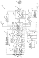
- a single lens reflex (SLR) photographic camera 10 of the sell-developing type which incorporates a preferred embodiment of the pre-exposure, reflectivity measuring exposure control system of the present invention.
- the camera 10 includes an objective or taking lens 12, of the fixed focus type, that may include one or more elements (only one shown) for focusing image-carrying light rays of, for example, an object 14 on a film plane 16 through an aperture formed in a shutter blade mechanism or assembly 18.
- the blade mechanism 18, positioned intermediate the lens 12 and the film plane 16 includes a pair of overlapping shutter blade elements 20A and 20B of the "scanning" type.
- Scene light admitting primary apertures 22A and 22B are respectively provided in the blade elements 20A and 20B to cooperatively define a progressive and predictable variation of effective aperture openings in accordance with simultaneous longitudinal and lateral displacement of one blade element with respect to the other blade element in a manner more fully described in commonly assigned U.S. Patent No. 3,942,183 to Whiteside.
- the blade element apertures are selectively shaped so as to overlay the central optical axis of the lens 12 thereby defining a gradually varying effective aperture size as a function of the position of the blades of the blade mechanism 18.
- a shutter drive 24 is provided for displacing the blade elements 20A and 20B.
- the shutter drive 24 includes a tractive electromagnetic device in the form of a solenoid (not shown) employed to displace the shutter blade elements with respect to one another in a manner more fully described in the above-cited Whiteside patent.
- Each of the blade elements 20A and 20B of the blade mechanism 18 includes two secondary apertures 26A, 28A and 26B, 28B, respectively.
- the aperture 26A in the blade 20A cooperates with the aperture 26B in the blade 20B to form an opening 30 and the aperture 28A in blade 20A cooperates with aperture 28B in blade 20B to form an opening 32 through the shutter assembly 18.
- These cooperating secondary apertures may be configured to track in a predetermined corresponding relationship with respect to the scene light admitting primary apertures 22A and 22B.
- the secondary apertures can move in the same manner as the primary apertures when the blade elements 20A and 20B are displaced, in the above-described manner, with respect to one another.
- the amount of artificial light admitted to the film plane 16 through the primary apertures 22A and 22B is controlled by a signal generated by a combination of an infrared photosensitive element 34 within an infrared sensor and an integrator 38 that senses and integrates a corresponding amount of infrared scene energy through the opening 30.
- the amount of visible ambient light admitted to the film plane 16 through these primary apertures is controlled by a signal generated by a combination of a visible light photosensitive element 40 within a visible light sensor 42 and an integrator 43 that senses and integrates a corresponding amount of visible ambient light, through the opening 32.
- An example of scanning blade elements having primary and secondary apertures that cooperate to control the amount of scene light admitted to a film plane is shown in U.S. Patent No. 3,942,183, supra.
- the camera 10 is provided with a blade position sensor/encoder 44.
- the sensor/encoder 44 senses the position of the blade elements 20A and 20B with respect to one another and generates a signal 46 representative of the relative blade element position.
- the sensor/encoder 44 comprises a light emitting diode 48, a photosensor 50 spaced therefrom, and a plurality of slots or openings 52 and 54 formed in the blade elements 20A and 20B, respectively.
- the slots 52, 54 are rectangular in shape, are of uniform size and are equally spaced in a linear direction in their respective blade elements 20A and 20B.
- the slots 52, 54 are interposed between the light emitting diode 48 and the photosensor 50 such that they alternately block and unblock the transmission of light between these two components to thereby cause the photosensor 50 to generate one or more pulses 46 representative of the relative position of the blade elements 20A and 20B.
- the position of the blade element 20A with respect to the blade element 20B defines the size of the effective or taking aperture formed by the primary apertures 22A and 22B in the blade mechanism 18. Therefore, the relative position of the blade elements 20A and 20B represented by the pulse or pulses 46 is also a measure of the size of the effective or taking aperture formed by the primary apertures 22A and 22B.
- the size of the slots 52, 54 in respective blade members 20A and 20B is kept to a minimum, in the direction of blade member movement, in order to minimize any blade position errors between the actual size of an effective aperture formed by the primary apertures 22A and 22B and the relative blade position pulse signals 46 representative of this particular aperture.
- the camera 10 is also provided with an electronic flash apparatus 56 together with apparatus for controlling its energization in order to determined subject reflectivity and to provide a portion of the exposure value required to illuminate a scene to be photographed.
- the electronic flash apparatus 56 comprises a main storage capacitor 58 which may be charged up to an operating voltage by any conventional voltage converter circuit (not shown) which would be included within a DC-DC voltage converter 60.
- the DC-DC voltage converter 60 operates in a conventional manner to convert a DC voltage as may be derived from a battery 62 of the camera 10, which can be in the order of 6 volts, to a suitable operating voltage such as 280 volts.
- a flash tube 64 and a series connected thyristor are collectively connected, in a parallel relation, with respect to the main storage capacitor 58.
- the flash tube 64 may be energized by a suitable trigger signal on a path 68 from a conventional trigger circuit (not shown) within an exposure control electronic module 70, and the thyristor 66 may be activated to its open state by a suitable trigger signal on a path 71 from another conventional trigger circuit (not shown) that is also included within the exposure control electronics module 70.
- the flash tube 64 illuminates the scene and subjects included therein with both visible and infrared light.
- the camera 10 additionally includes an empirically derived look-up table 72.
- the primary purpose of the look-up table 72 is to control the amount of image-carrying scene light rays focused on the film plane 16 by the lens 12 through the effective or taking aperture in the blade mechanism 18 formed by the primary apertures 22A and 22B, as a function of ambient scene light and of subject reflectivity.
- the amount of artificial and ambient scene light transmitted to the film plane 16 is indirectly measured by sensing a portion of the artificial and ambient scene light through the openings 30 and 32 in the blade mechanism 18 with the photosensor 34 located within the infrared light sensor 36 and its associated integrator 38 and the photosensor 40 located within the visible light sensor 42 and its associated integrator 43.
- a signal generated by the infrared sensor 36 and its associated integrator 38 representative of reflected infrared scene light is routed to the look-up table 72 through a path 74 and a signal generated by the visible light sensor 42 and its associated integrator 43 representative of ambient scene light is routed to the look-up table 72 through a path 76.
- the look-up table 72 generates a plurality of different signals in response to these two signals for controlling the amount of image-carrying light rays transmitted to the film plane 16 through the primary apertures in the blade mechanism 18. These plurality of different signals are derived for each exposure cycle, prior to an exposure interval. As an alternative, these signals may also be derived in the early stages of an exposure interval.
- the signals derived by the look-up table 72 are 1) an aperture size signal that controls the size of the taking aperture formed by the primary apertures 22A and 22B at which the flash tube 64 is fired, on an output path 78; 2) a percentage of artificial light signal that controls the amount of artificial light to be added to the scene to be photographed by the flash tube 64, on an output path 80; 3) a percentage of ambient light signal that controls the amount of image-carrying light to be admitted to the film plane 16 through the primary apertures 22A and 22B in the blade mechanism 18, on an output path 82; and 4) a signal to terminate the exposure interval at a time dependent upon the magnitude of the artificial and ambient light signals appearing on the input paths 74 and 76, respectively, to the look-up table 72, if the exposure interval is not sooner terminated, on an output path 84.
- the camera 10 is provided with an electronic flash apparatus 56 whose light output is employed to determine subject reflectivity and to provide a portion of the exposure value required to illuminate a scene to be photographed.
- the light output of the electronic flash apparatus 56 is employed during an exposure cycle prior to an exposure interval for the determination of subject reflectivity.
- the reflectivity of a subject within a scene is determined in the following manner.
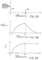
- the conventional trigger circuit within the exposure control electronics module 70 transmits a trigger signal 86 (Fig. 3A) on the path 68 to energize or initiate the firing of the flash tube 64.
- the flash tube 64 starts to illuminate the scene with visible and infrared light in the manner shown in Fig. 3B.
- the integrator 38 at the output of the infrared light sensor 36 is enabled by an enable signal from the exposure control electronics module 70 on a path 87.
- Fig. 3C is a graph of the integration of the output current from the infrared sensor 36 as a function of time by the integrator 38.
- a trigger signal 88 (Fig. 3A) on the path 71 to trigger the thyristor 66 to its open state and thereby initiate the extinguishing of the light output of the flash tube 64.
- the exposure control electronics module 70 disables the integrator 38 through the path 87 to terminate its integration of the output current of the infrared light sensor 36. It should be noted and as shown in Fig. 3B, even though the flash tube 64 is de-energized or triggered off at a particular time, it continues to illuminate the scene with light for a significant period thereafter.
- the initiating of the extinguishing of the light output from the flash tube 64 at the same time that the integrator 38 is disabled may introduce thyristor-generated-noise integration errors into the exposure control system of a magnitude that may not be tolerable. If this should occur, the integrator 38 could be disabled a few tenths of a microsecond before the triggering of the thyristor 66 and thereby avoid such errors.
- the disabling of the integrator 38 at the same time or before the initiating of the extinguishing of the light output from the flash tube 64 may result in an integration signal of insufficient magnitude for proper exposure control system operation.
- the integrator 38 may be disabled after the triggering of the thyristor 66 to its off or open state in order to increase the amount of light integrated thereby.
- additional circuitry may have to be added to compensate for the integration errors that would normally be produced when the integrator 38 integrates all of the noise generated by the actuation of the thyristor 66 to its off or open state, if such integration errors are unacceptable. No matter what point in time the integrator 38 is disabled, its final level of integration would constitute a signal representative of subject reflectivity.
- the ambient visible light signal already stored within the microcontroller 90 is then routed to the look-up table 72 through a path 94.
- This stored ambient visible light signal and the infrared signal subsequently generated by the infrared light sensor 36 and integrated by the integrator 38 are collectively employed within the look-up table 72 to generate the above-noted signals appearing on the output paths 78, 80, 82 and 84 from the look-up table 72.
- the signals appearing at the output paths 78, 80, 82 and 84 of the look-up table 72 in response to the infrared and ambient visible scene light signals respectively generated by the sensors 36 and 42 and their respective integrators 38 and 43, are empirically determined.
- the look-up table 72 is constructed in accordance with the subjective analysis of a multiplicity of photographic images of subjects located at various subject distances and having a range of reflectivities that are produced under a wide range of artificial and ambient scene light conditions, in order to generate these look-up table output signals.
- the look-up table 72 is constructed such that it performs a tradeoff between the sharpness of a subject within the scene and an overall photographic scene exposure. In performing this tradeoff, the look-up table 72 causes the flash tube 64 to fire at the smallest possible aperture, and therefore the greatest depth of field, that will provide the optimum subject sharpness and overall scene exposure.
- the look-up table 72 further improves the overall scene exposure in response to the infrared and visible light level signal generated by the sensors 36 and 42 by controlling the amount of artificial light generated hy the flash the 64 during an exposure interval and by controlling the maximum size of the taking aperture formed by the primary apertures 22A and 22B.
- the camera 10 is of the SLR type and therefore includes a conventional reflex mirror 96 that is actuatable by the exposure control electronics module 70 through the path 98.
- the mirror 96 is actuatable, in a conventional manner, between a viewing position where it blocks the transmission of scene light to the film plane 16 and where a camera operator can view a scene to be photographed through the lens 12, and a taking or unblocking position as shown in Fig. 1, where it facilitates the transmission of scene light to the film plane 16 during an exposure interval.
- the camera 10 is preferably designed for use with a self-developing film unit (not shown) similar to those described in U.S. Patent No. 3,415,644 to Land, in common assignment herewith, and specifically incorporated herein by reference.
- the self-developing film unit is packaged in a lighttight film cassette 100 shown in the condition assumed just after the cassette 100 has been fully inserted into the camera 10.
- the cassette 100 may enclose the 6 VDC battery 62.
- a film advancing apparatus 102 mounted within the camera 10 is a film advancing apparatus 102 similar to that described in U.S. Patent No. 3,753,392 to Land that includes a motor for operating a gear train (neither shown) which is coupled with the film advancing apparatus 102 to provide for the continuous movement of an exposed film unit from an exposure position within the camera 10 toward the exterior thereof.
- the film advancing apparatus 102 additionally includes a film-engaging arm member (not shown) driven by the above-mentioned motor and gear train.
- the arm member is adapted to extend into a slot in the cassette 100 and engage the uppermost film unit located therein at or near its trailing edge prior to moving it out of the cassette 100 and into the bite of a pair of conventional processing rollers (not shown) mounted adjacent the leading edge of the above-mentioned uppermost film unit.
- the processing rollers which are rotated by the motor and gear train mentioned above, continue the uninterrupted movement of the exposed film unit toward the exterior of the camera 10 while simultaneously rupturing a container of processing liquid at the leading end of the exposed film unit.
- the processing rollers spread the liquid contents of the ruptured container between elements of the film unit to initiate formation of a visible image within the film unit in a manner that is well-known in the art.
- FIG. 4 is a graph showing primary and secondary blade aperture size variations as a function of time during the typical exposure cycle.
- a switch 106 is actuated to its closed position by a camera operator to initiate an exposure cycle.
- the closure of the switch 106 couples the battery 62 to the exposure control electronics module 70 through a path 108.
- the exposure control electronics module 70 and the microcontroller 90 coupled thereto through a path 110, in turn, activate the visible light sensor 42 and the integrator 43 coupled to the visible light sensor 42, through a path 112.
- the integrator 43 is enabled to integrate ambient scene light for a fixed period of time and then send the final integrated value thereof to the look-up table 72 through the path 76 and then to the microcontroller 90 through the path 92 for temporary storage.
- the exposure control electronics module 70 energizes the shutter drive 24 to actuate the blade mechanism 18 and therefore the taking aperture together with the opening 30 formed by the secondary apertures 26A and 26B, and the opening 32 formed by the secondary apertures 28A and 28B, to their fully closed positions. Subsequent to the closing of the opening 30 in the shutter mechanism 18 and prior to the initiations of an exposure interval, the shutter drive 24 causes the opening 30 to increase in size toward its fully opened position.
- the exposure control electronics module 70 actuates means (not shown) for moving the mirror 96 from its viewing or light blocking position, where it precludes the transmission of image carrying light rays to the film plane 16, to its light unblocking position (as shown in Fig. 1), where it facilitates the transmission of image-carrying light rays to the film plane 16 during an exposure interval through the path 98.
- the exposure control electronics module 70 triggers the flash tube 64 through the path 68 to thereby illuminate a scene to be photographed with visible and infrared light prior to the initiation of an exposure interval.
- the exposure control electronics module 70 then triggers the thyristor 66 to its open or off state through the path 71 thirty-five microseconds after turning on the flash tube 64 to thereby initiate the extinguishing of the light output of the flash tube 64.
- This triggering on and off of the flash tube 64 constitutes a first pulse of light directed toward the scene to be photographed.
- the exposure control electronics module 70 also activates the infrared light sensor 36 and the integrator 38 coupled thereto through the path 89 for thirty-three microseconds or for two microseconds less than the period of time that the strobe 64 is triggered to its on or scene illuminating state.
- the exposure control electronics module 70 then causes the final value of the integrator 38, which constitutes a measure of subject reflectivity, to be sent to the look-up table 72 through the path 74.
- the look-up table 72 combines it with the ambient visible light signal previously stored in memory in the microcontroller 90.
- These combined signals are then employed to generate the aperture size flash fire signal, the percentage of artificial light signal, the percentage of ambient light signal and the end of exposure signal subsequently appearing on the look-up table output paths 78, 80, 82 and 84, respectively, that are, in turn, applied to the exposure control electronics module 70.
- the exposure control electronics module 70 actuates the shutter drive 24 and the blade mechanism 18 coupled thereto such that the opening 30 formed by the secondary apertures 26A and 26B is placed in its fully closed position and actuates the shutter drive 24 and the blade mechanism 18 to initiate an exposure interval.
- the exposure control electronics module 70 includes four conventional comparators (not shown) to determine when the four conditions represented by the look-up table output signals on the paths 78, 80, 82 and 84 and employed in the generation of an exposure interval have been achieved.
- An exposure interval is defined herein as the period of time that the shutter mechanism 18 allows image-carrying light rays collected by the lens 12 to reach the film plane 16.
- the first of the above-mentioned comparators compares the reference or desired aperture size flash fire signal on look-up table output path 78 with the blade position signal and therefore the taking aperture size as represented by the pulses 46 from the blade position sensor/encoder 44.
- this first comparator determines that these two signals are equal, the exposure control electronics module 70 once again triggers the flash tube 64 through the path 68 and thereby illuminates the scene being photographed with visible and infrared light during the exposure interval.
- the second of the above-mentioned comparators compares the reference or desired percentage of artificial light signal on look-up table output path 80 with the actual level of artificial light illuminating the scene as sensed by the infrared sensor 36, integrated by its associated integrator 38 and then routed to the exposure control electronics module 70 through the path 114.
- the exposure control electronics module 70 triggers the thyristor 66 to its open state through the path 71 to thereby cause the artificial light being generated by the flash tube 64 to be extinguished.
- This illumination of the scene with artificial light constitutes a second pulse of light that is directed toward the scene to be photographed.
- the third of the above-mentioned comparators compares the reference or desired percentage of visible light signal on look-up table output path 82 with the actual level of visible light illuminating the scene as sensed by the visible light sensor 42, integrated by its associated integrator 43 and then routed to the exposure control electronics module 70 through the path 112.
- the exposure control electronics module 70 activates the shutter drive 24 to close the taking aperture in the blade mechanism 18 and thereby terminate the exposure interval.
- a fourth comparator arrangement compares a signal on the look-up table output path 84 representative of the actual level of ambient or reflected scene light with a predeternnined reference signal stored within the exposure control electronics module 70.
- the exposure interval will be limited to a relatively short period of time such as 40 milliseconds whereas if this signal is less than the reference signal the exposure interval will be limited to a relatively long period of time such as 400 milliseconds unless terminated sooner by the presence of sufficient exposure levels of ambient and/or artificial scene light.
- the exposure control electronics module 70 actuates the mirror 96 toward its light-blocking position, and actuates the film advancing apparatus 102 and the drive motor (not shown) included therein, through a path 116, to initiate the transport and processing of an exposed, self-developing film unit.
- the film advancing apparatus moves the exposed film unit located in the cassette 100, through a path 118, into the bite of the pair of adjacent processing rollers (not shown), in the manner described above, to spread processing liquid between certain film layers and to move the exposed film unit into an exit slot (not shown) in a housing 120 of the self-developing camera 10.
- the exposure control electronics module 70 actuates the shutter drive 24 and the shutter mechanism 18 coupled thereto such that the primary or taking aperture thereof is placed in its fully opened position.
- a film movement completion signal is routed to the exposure control electronics module 70 and the microcontroller 90 coupled thereto through a path 122.
- the exposure control electronic module 70 initiates the charging of the electronic flash apparatus 56 through the path 105.
- the exposure control electronic module 70 places the exposure control system of the camera 10 in condition for the initiation of the next exposure cycle.
- a source of artificial light generated by the flash tube 64 was employed to illuminate the scene with both infrared and visible light.
- the flash tube 64 illuminated the scene twice during an exposure cycle, once before and once during the exposure interval. All of the energy required by the flash tube 64 to illuminate the scene both before and during an exposure interval is provided by a single storage capacitor described herein as the main discharge capacitor 58.
- the amount of time that energy is available to the flash tube 64 from the main discharge capacitor 58 prior to an exposure interval is limited to a predetermined period of time. In this the preferred embodiment, that period of time has been limited to 35 microseconds.
- Limiting the amount of time and therefore the amount of energy available to the flash tube 64 prior to an exposure interval reduces the range of distances over which it can be employed in the determination of subject reflectivity. However, by limiting the amount of time that energy is available to the flash tube 64 for reflectivity determination purposes prior to an exposure interval, the main discharge capacitor 58 is able to store sufficient energy, from a single capacitor charge, to power the flash tube 64 both before and during an exposure interval.
Landscapes
- Physics & Mathematics (AREA)
- General Physics & Mathematics (AREA)
- Stroboscope Apparatuses (AREA)
- Exposure Control For Cameras (AREA)
Claims (12)
- Appareil (10) pour mesurer le pouvoir de réflexion d'une scène photographique, qui comprend :- une source de lumière (56) pour éclairer la scène photographique, qui peut être excitée pendant un laps de temps fixé,- un moyen (36) sensible à la lumière pour détecter la lumière émise par ladite source de lumière et réfléchie par la scène et pour produire un signal en réponse à la lumière réfléchie,- un moyen d'intégration (38) couplé audit moyen sensible à la lumière pour intégrer ledit signal de réponse à la lumière réfléchie sur un intervalle de temps prédéterminé, la valeur finale de l'intégration représentant une mesure du pouvoir de réflexion de la scène, et- un moyen (70) pour exciter ladite source de lumière afin qu'elle éclaire la scène et produise ainsi ladite mesure du pouvoir de réflexion de la scène,caractérisé en ce que ledit intervalle de temps prédéterminé commence un temps de retard prédéterminé après l'activation (86) de ladite source de lumière (56).
- Appareil selon la revendication 1, dans lequel ledit temps de retard prédéterminé est égal à deux microsecondes.
- Appareil selon la revendication 1 ou 2, dans lequel ledit intervalle de temps prédéterminé se termine à la fin dudit laps de temps fixé.
- Appareil selon la revendication 1 ou 2, dans lequel ledit intervalle de temps prédéterminé se termine avant la fin dudit laps de temps fixé.
- Appareil selon la revendication 1 ou 2, dans lequel ledit intervalle de temps prédéterminé se termine après la fin dudit laps de temps fixé.
- Appareil selon l'une quelconque des revendications 1 à 5, dans lequel ledit laps de temps fixé vaut approximativement 35 microsecondes.
- Procédé de mesure du pouvoir de réflexion d'une scène photographique, comprenant les étapes consistant à :- exciter (86) une source de lumière (56) pour éclairer la scène photographique pendant un laps de temps fixé,- détecter la lumière émise par la source de lumière et réfléchie par la scène et produire un signal en réponse à la lumière réfléchie, et- intégrer le signal de réponse à la lumière réfléchie sur un intervalle de temps prédéterminé, la valeur finale de l'intégration étant une mesure du pouvoir de réflexion du sujet,caractérisé en ce que l'étape d'intégration du signal de réponse à la lumière réfléchie sur un intervalle de temps prédéterminé comprend une étape de retardement de l'intégration d'un temps de retard prédéterminé après l'activation de la source de lumière.
- Procédé selon la revendication 7, dans lequel l'étape de retardement de l'intégration du signal de réponse à la lumière réfléchie comprend un retard de deux microsecondes.
- Procédé selon la revendication 7 ou 8, dans lequel ledit intervalle de temps prédéterminé se termine à la fin (88) dudit laps de temps fixé.
- Procédé selon la revendication 7 ou 8, dans lequel ledit intervalle de temps prédéterminé se termine avant la fin (88) dudit laps de temps fixé.
- Procédé selon la revendication 7 ou 8, dans lequel ledit intervalle de temps prédéterminé se termine après la fin (88) dudit laps de temps fixé.
- Procédé selon l'une quelconque des revendications 7 à 11, dans lequel ledit laps de temps fixé est établi approximativement à 35 microsecondes.
Priority Applications (2)
| Application Number | Priority Date | Filing Date | Title |
|---|---|---|---|
| DE1990626826 DE69026826T2 (de) | 1990-10-16 | 1990-10-16 | Vorblitz-Me methode |
| AT90890282T ATE137592T1 (de) | 1990-10-16 | 1990-10-16 | Vorblitz-me methode |
Applications Claiming Priority (1)
| Application Number | Priority Date | Filing Date | Title |
|---|---|---|---|
| US07/414,267 US4998128A (en) | 1989-09-29 | 1989-09-29 | Preflash measurement technique |
Publications (2)
| Publication Number | Publication Date |
|---|---|
| EP0481158A1 EP0481158A1 (fr) | 1992-04-22 |
| EP0481158B1 true EP0481158B1 (fr) | 1996-05-01 |
Family
ID=23640702
Family Applications (1)
| Application Number | Title | Priority Date | Filing Date |
|---|---|---|---|
| EP90890282A Expired - Lifetime EP0481158B1 (fr) | 1989-09-29 | 1990-10-16 | Technique de mesure préflash |
Country Status (2)
| Country | Link |
|---|---|
| US (1) | US4998128A (fr) |
| EP (1) | EP0481158B1 (fr) |
Families Citing this family (10)
| Publication number | Priority date | Publication date | Assignee | Title |
|---|---|---|---|---|
| US5231448A (en) * | 1989-08-07 | 1993-07-27 | Nikon Corporation | Photometric apparatus for a camera |
| US5860029A (en) * | 1993-10-20 | 1999-01-12 | Minolta Co., Ltd. | Camera system having a flash device capable of performing a high speed synchronized photography |
| JP3591009B2 (ja) * | 1994-11-01 | 2004-11-17 | 株式会社ニコン | Ttl自動調光制御装置 |
| JP3639358B2 (ja) * | 1995-09-22 | 2005-04-20 | オリンパス株式会社 | 電子制御カメラ |
| US6151073A (en) * | 1996-03-28 | 2000-11-21 | Fotonation, Inc. | Intelligent camera flash system |
| US7978260B2 (en) * | 2003-09-15 | 2011-07-12 | Senshin Capital, Llc | Electronic camera and method with fill flash function |
| JP4999306B2 (ja) * | 2005-09-30 | 2012-08-15 | カシオ計算機株式会社 | 撮像装置、撮影方法及びプログラム |
| DE102006057190A1 (de) * | 2006-12-05 | 2008-06-12 | Carl Zeiss Meditec Ag | Verfahren zur Erzeugung hochqualitativer Aufnahmen der vorderen und/oder hinteren Augenabschnitte |
| TWI405458B (zh) * | 2010-07-02 | 2013-08-11 | Altek Corp | Digital camera sensitivity adjustment method |
| US8391702B2 (en) | 2010-12-17 | 2013-03-05 | Research In Motion Limited | Reduced pre-flash for LED flash based camera devices |
Family Cites Families (11)
| Publication number | Priority date | Publication date | Assignee | Title |
|---|---|---|---|---|
| US3173347A (en) * | 1963-03-06 | 1965-03-16 | Eastman Kodak Co | Autoamtic exposure control for a camera |
| US3415644A (en) * | 1967-03-10 | 1968-12-10 | Polaroid Corp | Novel photographic products and processes |
| US3753302A (en) * | 1972-11-10 | 1973-08-21 | Ford Motor Co | Anthropomorphic test dummy torso |
| US3942183A (en) * | 1974-07-02 | 1976-03-02 | Polaroid Corporation | Camera with pivoting blades |
| JPS54128734A (en) * | 1978-03-29 | 1979-10-05 | Minolta Camera Co Ltd | Flash discharger enabled to effect preparatory flash |
| US4302084A (en) * | 1980-03-10 | 1981-11-24 | Eastman Kodak Company | Automatic rangefinding device for use in a camera |
| US4357083A (en) * | 1980-10-06 | 1982-11-02 | Polaroid Corporation | Method and apparatus using weighted range signal for controlling photographic functions |
| US4549801A (en) * | 1983-03-21 | 1985-10-29 | W. Haking Enterprises Limited | Automatic focussing camera with automatic aperture setting |
| GB2170320B (en) * | 1984-12-28 | 1988-12-21 | Canon Kk | Camera system |
| US4785322A (en) * | 1987-12-10 | 1988-11-15 | Polaroid Corporation | Infrared wink ranging system |
| US4894678A (en) * | 1989-05-01 | 1990-01-16 | Polaroid Corporation | Preflash pseudofocus/exposure control system |
-
1989
- 1989-09-29 US US07/414,267 patent/US4998128A/en not_active Expired - Lifetime
-
1990
- 1990-10-16 EP EP90890282A patent/EP0481158B1/fr not_active Expired - Lifetime
Also Published As
| Publication number | Publication date |
|---|---|
| EP0481158A1 (fr) | 1992-04-22 |
| US4998128A (en) | 1991-03-05 |
Similar Documents
| Publication | Publication Date | Title |
|---|---|---|
| US4357083A (en) | Method and apparatus using weighted range signal for controlling photographic functions | |
| CA2028640C (fr) | Appareil de compensation des variations dans la vitesse d'obturation et methode connexe | |
| EP0481158B1 (fr) | Technique de mesure préflash | |
| US5159381A (en) | Electronic flash control circuit | |
| CA2027515C (fr) | Methode de mesure pre-eclair | |
| EP0066383B1 (fr) | Système de contrôle d'exposition photographique avec flash d'appoint | |
| US4894678A (en) | Preflash pseudofocus/exposure control system | |
| US4317622A (en) | Exposure control apparatus for flash photography | |
| US4972217A (en) | Shutter mechanism drive having reduced mechanical noise | |
| US5051768A (en) | Electronic flash apparatus for reducing the incidence of human eyelid closures during exposure | |
| EP0108979B1 (fr) | Dispositif de caméra hybride | |
| US4978991A (en) | Open-loop stepper motor controlled shutter | |
| US5189464A (en) | Supplemental lens positioning system for a fixed focus lens camera | |
| US5117252A (en) | Electronic flash control system for use in a fixed focus lens camera for increasing depth of field by the timing of flash actuation | |
| US5124739A (en) | Real time pseudofocus exposure control system | |
| CA1208060A (fr) | Appareil hydride de prise de vues | |
| JP2989658B2 (ja) | 自動露出決定方法及び装置並びにこれを用いたカメラ | |
| EP0319798B1 (fr) | Réglage d'exposition à temps d'exposition fixe aux niveaux élevés de lumière | |
| US4290683A (en) | Sonar responsive shutter blade time out control circuit | |
| US4941011A (en) | Single integrator system with dual photocells | |
| CA1157307A (fr) | Appareil photo a flash stroboscopique automatique |
Legal Events
| Date | Code | Title | Description |
|---|---|---|---|
| PUAI | Public reference made under article 153(3) epc to a published international application that has entered the european phase |
Free format text: ORIGINAL CODE: 0009012 |
|
| AK | Designated contracting states |
Kind code of ref document: A1 Designated state(s): AT BE CH DE DK ES FR GB GR IT LI LU NL SE |
|
| 17P | Request for examination filed |
Effective date: 19921015 |
|
| 17Q | First examination report despatched |
Effective date: 19940707 |
|
| GRAH | Despatch of communication of intention to grant a patent |
Free format text: ORIGINAL CODE: EPIDOS IGRA |
|
| GRAA | (expected) grant |
Free format text: ORIGINAL CODE: 0009210 |
|
| AK | Designated contracting states |
Kind code of ref document: B1 Designated state(s): AT BE CH DE DK ES FR GB GR IT LI LU NL SE |
|
| PG25 | Lapsed in a contracting state [announced via postgrant information from national office to epo] |
Ref country code: IT Free format text: LAPSE BECAUSE OF FAILURE TO SUBMIT A TRANSLATION OF THE DESCRIPTION OR TO PAY THE FEE WITHIN THE PRESCRIBED TIME-LIMIT;WARNING: LAPSES OF ITALIAN PATENTS WITH EFFECTIVE DATE BEFORE 2007 MAY HAVE OCCURRED AT ANY TIME BEFORE 2007. THE CORRECT EFFECTIVE DATE MAY BE DIFFERENT FROM THE ONE RECORDED. Effective date: 19960501 Ref country code: ES Free format text: THE PATENT HAS BEEN ANNULLED BY A DECISION OF A NATIONAL AUTHORITY Effective date: 19960501 Ref country code: BE Effective date: 19960501 Ref country code: CH Effective date: 19960501 Ref country code: DK Effective date: 19960501 Ref country code: AT Effective date: 19960501 Ref country code: NL Free format text: LAPSE BECAUSE OF FAILURE TO SUBMIT A TRANSLATION OF THE DESCRIPTION OR TO PAY THE FEE WITHIN THE PRESCRIBED TIME-LIMIT Effective date: 19960501 Ref country code: LI Effective date: 19960501 Ref country code: GR Free format text: LAPSE BECAUSE OF FAILURE TO SUBMIT A TRANSLATION OF THE DESCRIPTION OR TO PAY THE FEE WITHIN THE PRESCRIBED TIME-LIMIT Effective date: 19960501 |
|
| REF | Corresponds to: |
Ref document number: 137592 Country of ref document: AT Date of ref document: 19960515 Kind code of ref document: T |
|
| ET | Fr: translation filed | ||
| REF | Corresponds to: |
Ref document number: 69026826 Country of ref document: DE Date of ref document: 19960605 |
|
| PG25 | Lapsed in a contracting state [announced via postgrant information from national office to epo] |
Ref country code: SE Effective date: 19960801 |
|
| NLV1 | Nl: lapsed or annulled due to failure to fulfill the requirements of art. 29p and 29m of the patents act | ||
| PG25 | Lapsed in a contracting state [announced via postgrant information from national office to epo] |
Ref country code: LU Free format text: LAPSE BECAUSE OF NON-PAYMENT OF DUE FEES Effective date: 19961031 |
|
| REG | Reference to a national code |
Ref country code: CH Ref legal event code: PL |
|
| PLBE | No opposition filed within time limit |
Free format text: ORIGINAL CODE: 0009261 |
|
| STAA | Information on the status of an ep patent application or granted ep patent |
Free format text: STATUS: NO OPPOSITION FILED WITHIN TIME LIMIT |
|
| 26N | No opposition filed | ||
| PGFP | Annual fee paid to national office [announced via postgrant information from national office to epo] |
Ref country code: FR Payment date: 20000911 Year of fee payment: 11 |
|
| PGFP | Annual fee paid to national office [announced via postgrant information from national office to epo] |
Ref country code: GB Payment date: 20000919 Year of fee payment: 11 |
|
| PGFP | Annual fee paid to national office [announced via postgrant information from national office to epo] |
Ref country code: DE Payment date: 20000925 Year of fee payment: 11 |
|
| PG25 | Lapsed in a contracting state [announced via postgrant information from national office to epo] |
Ref country code: GB Free format text: LAPSE BECAUSE OF NON-PAYMENT OF DUE FEES Effective date: 20011016 |
|
| REG | Reference to a national code |
Ref country code: GB Ref legal event code: IF02 |
|
| GBPC | Gb: european patent ceased through non-payment of renewal fee |
Effective date: 20011016 |
|
| PG25 | Lapsed in a contracting state [announced via postgrant information from national office to epo] |
Ref country code: FR Free format text: LAPSE BECAUSE OF NON-PAYMENT OF DUE FEES Effective date: 20020628 |
|
| PG25 | Lapsed in a contracting state [announced via postgrant information from national office to epo] |
Ref country code: DE Free format text: LAPSE BECAUSE OF NON-PAYMENT OF DUE FEES Effective date: 20020702 |
|
| REG | Reference to a national code |
Ref country code: FR Ref legal event code: ST |