EP0481183A2 - Dispositif pour séparer les lamelles dans les appareils à passer les fils de chaîne - Google Patents
Dispositif pour séparer les lamelles dans les appareils à passer les fils de chaîne Download PDFInfo
- Publication number
- EP0481183A2 EP0481183A2 EP91113484A EP91113484A EP0481183A2 EP 0481183 A2 EP0481183 A2 EP 0481183A2 EP 91113484 A EP91113484 A EP 91113484A EP 91113484 A EP91113484 A EP 91113484A EP 0481183 A2 EP0481183 A2 EP 0481183A2
- Authority
- EP
- European Patent Office
- Prior art keywords
- lamella
- stack
- lamellae
- stop
- plates
- Prior art date
- Legal status (The legal status is an assumption and is not a legal conclusion. Google has not performed a legal analysis and makes no representation as to the accuracy of the status listed.)
- Withdrawn
Links
Images


Classifications
-
- D—TEXTILES; PAPER
- D03—WEAVING
- D03J—AUXILIARY WEAVING APPARATUS; WEAVERS' TOOLS; SHUTTLES
- D03J1/00—Auxiliary apparatus combined with or associated with looms
- D03J1/14—Apparatus for threading warp stop-motion droppers, healds, or reeds
-
- D—TEXTILES; PAPER
- D03—WEAVING
- D03D—WOVEN FABRICS; METHODS OF WEAVING; LOOMS
- D03D47/00—Looms in which bulk supply of weft does not pass through shed, e.g. shuttleless looms, gripper shuttle looms, dummy shuttle looms
Definitions
- the present invention relates to a device for separating lamellae in warp threading machines, with a dividing element for the lamellae fed in the form of a stack, which separates them from the stack and prepares them for the warp threading.
- the compartment member is formed by a compartment knife entering the plate stack from above, which pierces directly after the foremost plate of the plate stack and shifts the foremost plate in the longitudinal direction of the plate stack to the retracted position.
- a compartment knife entering the plate stack from above, which pierces directly after the foremost plate of the plate stack and shifts the foremost plate in the longitudinal direction of the plate stack to the retracted position.
- the invention is now to provide a universally usable device for separating lamellae, which enables the division of all types of lamellae without these having to be specially lined up.
- the compartment member is formed by means of a means that engages the end face of the stack of lamellae and the foremost lamella in a force-fitting manner from the stack of lamellae to an intermediate position.
- the compartment organ acts on the end face of the stack of lamellae and does not pierce it laterally, the lamellae need not have a special shape at the puncture point and they do not need to be specially lined up or arranged. Rather, the compartment member contacting the slats on its end face is able to separate all types of slats.
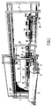
- the drawing-in machine consists of a base frame 1 and of various assemblies arranged in it, each of which forms a functional module.
- a warp beam carriage 2 with a warp beam 3 arranged on it can be seen in front of the base frame 1.
- the warp beam carriage 3 also contains a lifting device 4 for holding a frame 5 on which the warp threads KF are stretched. This clamping takes place before the actual pulling-in and at a location separate from the drawing-in machine, the frame 5 being positioned at the lower end of the lifting device 4 in the immediate vicinity of the warp beam 3.
- the warp beam carriage 2 with the warp beam 3 and lifting device 4 is moved to the so-called upgrade side of the pulling-in machine and the frame 5 is lifted up by the lifting device 4 and then assumes the position shown.
- the frame 5 and the warp beam 3 are moved in the longitudinal direction of the base frame 1. During this shifting, the warp threads KF are guided past a thread separation group 6 and are separated and divided in the process. After division, the warp threads KF are cut off and presented to a pull-in needle 7, which forms part of the so-called feed module.
- the sectioning device used in the USTER TOPMATIC warp knitting machine (USTER - registered trademark of Zellweger Uster AG), for example, can be used for dividing the warp threads.
- a monitor 8 which belongs to an operating station and is used to display machine functions and machine malfunctions and for data input.
- the operating station which forms part of a so-called programming module, also contains an input stage for the manual input of certain functions, such as crawl gear, start / stop, repetition of operations, and the like.
- the drawing-in machine is controlled by a control module containing a control computer, which is arranged in a control box 9.
- this control box contains a module computer for each so-called main module, the individual module computers being controlled and monitored by the control computer.
- the main modules of the drawing machine are, in addition to the modules already mentioned, drawing module, yarn module, control module and programming module, the strand, the lamella and the sheet module.
- the thread separation group 6, which presents the warp threads to be drawn in to the pull-in needle 7, and the path of movement of the pull-in needle 7, which is vertical to the plane of the stretched Warp threads KF determine a plane in the area of a support 10 forming part of the base frame 1, which separates the already mentioned upgrade side from the so-called teardown side of the drawing-in machine.
- the warp threads and the individual elements into which the warp threads are to be fed are fed in on the upgrade side, and the so-called dishes (strands, lamellae and sheets) with the drawn-in warp threads can be removed on the tear-down side.
- the frame 5 with the warp threads KF and the warp beam carriage 2 with the warp beam 3 are moved past the thread separating group 6 to the right, the pull-in needle 7 successively taking out the warp threads KF stretched on the frame 5.
- the warp thread monitor slats LA Immediately behind the plane of the warp threads KF are the warp thread monitor slats LA, behind them the healds LI and even further behind the reed.
- the lamellae LA are stacked in hand magazines, and the full hand magazines are hung in inclined feed rails 11, on which they are transported to the right, towards the pull-in needle 7. There they are separated and brought into the feed position. After pulling in, the lamellae LA arrive on lamella support rails 12 on the dismantling side.
- the strands LI are lined up on rails 13 and manually or automatically shifted to a separation stage on them. Then the healds LI are individually brought into their retracted position and, after they have been drawn in, are distributed to the corresponding heald frames 14 on the dismantling side. The reed is also moved past the retracting needle 7 step by step, the corresponding gap in the sheet being opened for the retraction. After being drawn in, the sheet is also on the dismantling side. To the right of the heald frames 14 is a part of the reed WB. This illustration is to be understood purely for illustrative purposes, since the reed is of course located on the upgrade page in the position of the frame 5 shown.
- a so-called crockery trolley 15 is provided on the dismantling side. This is inserted together with the slat support rails 12, heald frames 14 and a holder for the reed attached to the base frame 1 in the position shown and carries the dishes with the drawn-in warp threads KF after being drawn in.
- the warp beam carriage 2 with the warp beam 3 is located directly in front of the dishwashing carriage 15.
- the dishes are reloaded from the dishwashing carriage 15 onto the warp beam carriage 2, which then carries the warp beam 3 and the pulled-in dishes and to the relevant weaving machine or can be moved to an interim storage facility.
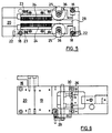
- This sub-module which is shown in FIGS. 2-6 in different views, follows in the transport direction of the lamella LA to the sub-module lamella magazine, which is described in CH patent application No. 01 694 / 90-5.
- the slat magazine sub-module essentially consists of a movable elongated frame in which the feed rails 11 for the hand magazines with the slats LA (FIG. 1) are mounted.
- the hand magazines are loaded with lamellae and suspended in the feed rails 11, in which they are transported against a separating station, at which one The slats are separated. This separating station will now be described with reference to FIGS. 2-6.
- the separating station is designed in the form of an elongated box, one end face (FIG. 2, left) of which is provided as the input side and the other end face of which (FIG. 2, right of the center) is the output side for the slats.
- the slats are pushed into the separating station by the hand magazines of the slat magazine sub-module, and on the output side, the slats are separated from their stack, with the individual slats being discharged sequentially from the separating station.
- the separating station is therefore connected on its left in FIGS. 2, 5 and 6 to the frame forming the sub-module lamella magazine, preferably by means of a corresponding coupling, which in FIG.
- a functional stage (not shown in more detail) is arranged, which takes over the slats output by the separating station and transfers them to a distribution station which positions the slats in the warp threading position.
- the box-shaped part of the separating station in which the lamellae LA are guided from the input to the output side, essentially consists of a rectangular base plate 17, in which a guide rod 18 is arranged in three corner points, and a cover plate 19 or intermediate plate 20 each carried and guided by these guide rods.
- the fourth corner point of the rectangle is therefore not occupied by a guide rod 18, because in the area of this corner point the connection between the separating station and the slat magazine sub-module (FIG. 6, recess 16).
- the intermediate plate 20 is adjustable in height to adapt to the various slat lengths; For this purpose, two of the guide rods 18 are provided with spaced grooves 21, into which corresponding fixing screws 22 engage.
- a pair of guide rails 23 is screwed to the cover plate 19 and the intermediate plate 20 on the mutually facing inner surfaces of these plates.
- Strip brushes 24 are screwed onto the guide rails 23 for exact lateral guidance of the slats LA. These strip brushes extend from the input side of the separating station to vertically arranged rotating brushes 25, which move the lamellae reaching their effective area in the transport direction (arrow A) until they stop. This stop is located in the connecting plane of the axes of the two guide rods 18 arranged to the right of the rotating brushes 25 in FIG.
- the upper web 26 is assigned a nose 30 adjustable via a crank 29, the distance from the web 26 of which can be set to predetermined values, as a result of which a slot of a defined width is formed between the web 26 and the nose 30.
- This width lies between the single and the double thickness of the lamella LA to be processed, so that only one lamella can be discharged from its stack through the slot mentioned above.
- the rotating brushes 25 and the friction wheel 31 are driven by a common motor 34 which is fastened to the base plate 17 and on the one hand the flexible shaft 34 directly and on the other hand the rotating brushes 25 via a belt and Gear drive 35 drives indirectly.
- This belt and gear drive 35 acts on the rotating brushes 25 carrying drive shafts 36, which are mounted at their upper end in the cover plate 19 so that their mutual distance is adjustable and thus adjustable to the width of the respective slats LA.
- the drive shafts 36 with the rotating brushes 25 are pressed resiliently against the side edges of the plate stack.
- the partitioning process can be supported by the fact that after the lamella has been released, a knife-like organ engages in the gap that now exists between the vertically hanging front lamella and the sloping stack of lamellae and pulls the lamella stack so far back against the transport direction A that There is only a small amount of friction between the foremost lamella and the lamella stack, so that in particular the head edge of the lamella just pushed upwards from the lamella stack does not damage the next following lamella.
Landscapes
- Engineering & Computer Science (AREA)
- Textile Engineering (AREA)
- Sheets, Magazines, And Separation Thereof (AREA)
- Auxiliary Weaving Apparatuses, Weavers' Tools, And Shuttles (AREA)
- Looms (AREA)
- Pinball Game Machines (AREA)
Applications Claiming Priority (2)
| Application Number | Priority Date | Filing Date | Title |
|---|---|---|---|
| CH2699/90 | 1990-08-20 | ||
| CH2699/90A CH682576A5 (de) | 1990-08-20 | 1990-08-20 | Vorrichtung zum Vereinzeln von Lamellen in Kettfadeneinziehmaschinen. |
Publications (2)
| Publication Number | Publication Date |
|---|---|
| EP0481183A2 true EP0481183A2 (fr) | 1992-04-22 |
| EP0481183A3 EP0481183A3 (fr) | 1992-05-06 |
Family
ID=4239603
Family Applications (1)
| Application Number | Title | Priority Date | Filing Date |
|---|---|---|---|
| EP19910113484 Withdrawn EP0481183A3 (fr) | 1990-08-20 | 1991-08-12 | Dispositif pour séparer les lamelles dans les appareils à passer les fils de chaíne |
Country Status (7)
| Country | Link |
|---|---|
| US (1) | US5174000A (fr) |
| EP (1) | EP0481183A3 (fr) |
| JP (1) | JPH04263651A (fr) |
| KR (1) | KR920004630A (fr) |
| CA (1) | CA2046190A1 (fr) |
| CH (1) | CH682576A5 (fr) |
| PT (1) | PT98715A (fr) |
Cited By (2)
| Publication number | Priority date | Publication date | Assignee | Title |
|---|---|---|---|---|
| WO1993018215A1 (fr) * | 1992-03-11 | 1993-09-16 | Zellweger Uster Ag | Dispositif de separation de lamelles pour machines a passer les fils de chaine |
| US5459913A (en) * | 1993-09-13 | 1995-10-24 | Staubli Ag | Heald carrier rails having control clamps for holding rails and limiting movement of healds |
Families Citing this family (7)
| Publication number | Priority date | Publication date | Assignee | Title |
|---|---|---|---|---|
| CH687881A5 (de) * | 1993-09-13 | 1997-03-14 | Staeubli Ag Zweigwerk Sargans | Litzensepariervorrichtung fuer Kettfadeneinziehmaschinen. |
| JPH09195149A (ja) * | 1996-01-12 | 1997-07-29 | Hamamatsu Photonics Kk | ワイヤヘルド用ストッカ |
| US7318456B2 (en) * | 2005-04-25 | 2008-01-15 | Massachusetts Institute Of Technology | Modular weaving system with individual yarn control |
| US7178558B2 (en) * | 2005-04-25 | 2007-02-20 | Massachusetts Institute Of Technology | Modular weaving for short production runs |
| EP1870501A1 (fr) * | 2006-06-23 | 2007-12-26 | Stäubli AG Pfäffikon | Dispositif de séparation de fils d'une couche de fils, procédé pour opérer le dit dispositif et utilisation du dit dispositif |
| KR200454776Y1 (ko) * | 2008-10-20 | 2011-07-28 | 코오롱글로텍주식회사 | 이동식 통경장치 |
| CN110079923A (zh) * | 2019-05-21 | 2019-08-02 | 深圳市海弘装备技术有限公司 | 一种停经片的分离、转移、排出的装置与方法 |
Family Cites Families (13)
| Publication number | Priority date | Publication date | Assignee | Title |
|---|---|---|---|---|
| DE688493C (de) * | 1939-02-12 | 1940-02-22 | App & Maschinenfabriken Uster | Verfahren und Einrichtung zum Abteilen einzelner magnetisierbarer Glieder von einem Stapel, insbesondere von einem aus Kettenfadenwaechterlamellen bestehenden Stapel |
| FR943930A (fr) * | 1946-05-03 | 1949-03-22 | Zellweger Uster Ag | Dispositif de pose des lamelles des casse-chaîne |
| GB709424A (en) * | 1951-02-02 | 1954-05-26 | Tmm Research Ltd | Improvements in means for separating the endmost member from a stack or bank of metal drop-pins for loom warp stop-motions |
| US2746119A (en) * | 1954-03-22 | 1956-05-22 | Zellweger Uster Ag | Device for arranging wire heddles on rods in warp drawing machines |
| GB781937A (en) * | 1954-03-22 | 1957-08-28 | Zellweger Uster Ag | Improvements relating to devices for arranging healds |
| CH479735A (de) * | 1968-12-20 | 1969-10-15 | Zellweger Uster Ag | Webketteneinziehmaschine |
| DE1919743A1 (de) * | 1969-02-17 | 1970-09-03 | Guido Herrmann Maschf | Vorrichtung zum Abteilen von Kettenfadenwaechterlamellen aus einem Stapel und Hinreichen derselben zum Einziehen der Kettfaeden |
| JPS4822145B1 (fr) * | 1970-05-14 | 1973-07-04 | ||
| CH578635A5 (fr) * | 1973-08-04 | 1976-08-13 | Dornier Gmbh Lindauer | |
| US4047270A (en) * | 1974-09-04 | 1977-09-13 | Lindauer Dornier Gesellschaft Mbh. | Apparatus for separating objects |
| DE3139626C2 (de) * | 1981-10-06 | 1983-10-06 | Lindauer Dornier Gmbh, 8990 Lindau | Vorrichtung zum Vereinzeln von Weblitzen, Lamellen o.dgl |
| JPS6420359A (en) * | 1987-07-10 | 1989-01-24 | Teijin Seiki Co Ltd | Heald transfer apparatus |
| JPH06104947B2 (ja) * | 1988-04-28 | 1994-12-21 | シーケーデイ株式会社 | 織機の綜絖等の分離装置 |
-
1990
- 1990-08-20 CH CH2699/90A patent/CH682576A5/de not_active IP Right Cessation
-
1991
- 1991-07-04 CA CA002046190A patent/CA2046190A1/fr not_active Abandoned
- 1991-07-08 KR KR1019910011482A patent/KR920004630A/ko not_active Withdrawn
- 1991-07-31 JP JP3278991A patent/JPH04263651A/ja active Pending
- 1991-08-12 EP EP19910113484 patent/EP0481183A3/fr not_active Withdrawn
- 1991-08-19 PT PT98715A patent/PT98715A/pt not_active Application Discontinuation
- 1991-08-20 US US07/747,345 patent/US5174000A/en not_active Expired - Fee Related
Cited By (3)
| Publication number | Priority date | Publication date | Assignee | Title |
|---|---|---|---|---|
| WO1993018215A1 (fr) * | 1992-03-11 | 1993-09-16 | Zellweger Uster Ag | Dispositif de separation de lamelles pour machines a passer les fils de chaine |
| US5448811A (en) * | 1992-03-11 | 1995-09-12 | Zellweger Luwa Ag | Drop-wire separation device for warp drawing-in machines |
| US5459913A (en) * | 1993-09-13 | 1995-10-24 | Staubli Ag | Heald carrier rails having control clamps for holding rails and limiting movement of healds |
Also Published As
| Publication number | Publication date |
|---|---|
| US5174000A (en) | 1992-12-29 |
| JPH04263651A (ja) | 1992-09-18 |
| KR920004630A (ko) | 1992-03-27 |
| CH682576A5 (de) | 1993-10-15 |
| CA2046190A1 (fr) | 1992-02-21 |
| EP0481183A3 (fr) | 1992-05-06 |
| PT98715A (pt) | 1993-09-30 |
Similar Documents
| Publication | Publication Date | Title |
|---|---|---|
| EP0500848B1 (fr) | Dispositif pour la manutention de lisses ou de lamelles dans une machine a rentrer les fils de chaine | |
| EP0646668B1 (fr) | Dispositif séparation de lisses pour les machines à rentrer les fils de chaîne | |
| CH653065A5 (de) | Vorrichtung zum vereinzeln von weblitzen oder lamellen. | |
| EP0448957B1 (fr) | Dispositif pour séparer les lisses dans les appareils à passer les fils de chaîne | |
| EP0481183A2 (fr) | Dispositif pour séparer les lamelles dans les appareils à passer les fils de chaîne | |
| DE2127310C3 (de) | Fördereinrichtung für Flaschen oder ähnliches Fördergut | |
| EP0501222A1 (fr) | Dispositif pour passer un fil de chaine dans un métier à tisser | |
| EP0646667B1 (fr) | Dispositif pour la manutention de lisses dans les machines à rentrer les fils de chaîne | |
| EP0460129B1 (fr) | Dispositif pour le remettage de fils de chaine | |
| EP0646669B1 (fr) | Dispositif pour le transfert sélectif de lisses | |
| EP0510140B1 (fr) | Machine pour le remettage automatique des fils de chaine | |
| DE2230644B2 (de) | Vorrichtung zum automatischen Zuführen von Textilfaserbändern aus Behältern zu Verarbeitungsmaschinen | |
| DE60116289T3 (de) | Weben von teppichen | |
| EP0584308B1 (fr) | Dispositif de separation de lamelles pour machines a passer les fils de chaine | |
| EP0457145B1 (fr) | Dispositif de manipulation de lamelles pour machines de rentrage des fils de chaîne | |
| EP0496232B1 (fr) | Dispositif pour la manipulation des lamelles pour machines de rentrage des fils de chaîne | |
| DE2547114C2 (fr) | ||
| EP1177339B1 (fr) | Dispositif et procede pour le transfert d'elements de harnais separes a un dispositif de transport | |
| CH680076A5 (en) | Assembly to draw warp yarns into harness sections of loom - comprises oscillating warp drawing-in unit of flexible strip carrying gripper with interrupted channel guide | |
| DE10133533A1 (de) | Verfahren zum Beschicken eines Magazins oder einer Schablone mit streifen- oder plattenförmigen Bauteilen sowie Vorrichtung zur Durchführung des Verfahrens | |
| DE1222866B (de) | Vorrichtung zum Ordnen von Schussspulen mit Fadenresten | |
| DE1114747B (de) | Vorrichtung zum Ordnen von Spulen, insbesondere von mit Garnresten behafteten Schussspulen |
Legal Events
| Date | Code | Title | Description |
|---|---|---|---|
| PUAI | Public reference made under article 153(3) epc to a published international application that has entered the european phase |
Free format text: ORIGINAL CODE: 0009012 |
|
| PUAL | Search report despatched |
Free format text: ORIGINAL CODE: 0009013 |
|
| AK | Designated contracting states |
Kind code of ref document: A2 Designated state(s): AT BE DE DK ES FR GB IT |
|
| AK | Designated contracting states |
Kind code of ref document: A3 Designated state(s): AT BE DE DK ES FR GB IT |
|
| 17P | Request for examination filed |
Effective date: 19921103 |
|
| 17Q | First examination report despatched |
Effective date: 19940504 |
|
| STAA | Information on the status of an ep patent application or granted ep patent |
Free format text: STATUS: THE APPLICATION IS DEEMED TO BE WITHDRAWN |
|
| 18D | Application deemed to be withdrawn |
Effective date: 19940915 |