EP0481334B1 - Dickenmessgerät zum Messen der auf einem Substrat liegenden Schicht - Google Patents
Dickenmessgerät zum Messen der auf einem Substrat liegenden Schicht Download PDFInfo
- Publication number
- EP0481334B1 EP0481334B1 EP91117145A EP91117145A EP0481334B1 EP 0481334 B1 EP0481334 B1 EP 0481334B1 EP 91117145 A EP91117145 A EP 91117145A EP 91117145 A EP91117145 A EP 91117145A EP 0481334 B1 EP0481334 B1 EP 0481334B1
- Authority
- EP
- European Patent Office
- Prior art keywords
- coating
- indicator
- housing
- thickness
- force
- Prior art date
- Legal status (The legal status is an assumption and is not a legal conclusion. Google has not performed a legal analysis and makes no representation as to the accuracy of the status listed.)
- Expired - Lifetime
Links
- 238000000576 coating method Methods 0.000 title claims abstract description 94
- 239000011248 coating agent Substances 0.000 title claims abstract description 89
- 239000000758 substrate Substances 0.000 title claims abstract description 26
- 238000005259 measurement Methods 0.000 claims abstract description 35
- 230000005484 gravity Effects 0.000 claims abstract description 33
- 229910052761 rare earth metal Inorganic materials 0.000 claims abstract description 32
- 230000005291 magnetic effect Effects 0.000 claims description 43
- 230000005294 ferromagnetic effect Effects 0.000 claims description 16
- 239000000523 sample Substances 0.000 claims description 15
- 238000000034 method Methods 0.000 claims description 10
- 230000002093 peripheral effect Effects 0.000 claims description 2
- 230000001419 dependent effect Effects 0.000 abstract 1
- 238000009675 coating thickness measurement Methods 0.000 description 22
- 239000000203 mixture Substances 0.000 description 11
- XEEYBQQBJWHFJM-UHFFFAOYSA-N Iron Chemical compound [Fe] XEEYBQQBJWHFJM-UHFFFAOYSA-N 0.000 description 5
- 229910045601 alloy Inorganic materials 0.000 description 3
- 239000000956 alloy Substances 0.000 description 3
- 239000000463 material Substances 0.000 description 3
- 230000007704 transition Effects 0.000 description 3
- 229910052684 Cerium Inorganic materials 0.000 description 2
- 229910052692 Dysprosium Inorganic materials 0.000 description 2
- 229910052691 Erbium Inorganic materials 0.000 description 2
- 229910052693 Europium Inorganic materials 0.000 description 2
- 229910052688 Gadolinium Inorganic materials 0.000 description 2
- 229910052689 Holmium Inorganic materials 0.000 description 2
- 229910052765 Lutetium Inorganic materials 0.000 description 2
- 229910052779 Neodymium Inorganic materials 0.000 description 2
- PXHVJJICTQNCMI-UHFFFAOYSA-N Nickel Chemical compound [Ni] PXHVJJICTQNCMI-UHFFFAOYSA-N 0.000 description 2
- 229910052777 Praseodymium Inorganic materials 0.000 description 2
- 229910052772 Samarium Inorganic materials 0.000 description 2
- 229910052771 Terbium Inorganic materials 0.000 description 2
- 229910052775 Thulium Inorganic materials 0.000 description 2
- 229910052769 Ytterbium Inorganic materials 0.000 description 2
- GWXLDORMOJMVQZ-UHFFFAOYSA-N cerium Chemical compound [Ce] GWXLDORMOJMVQZ-UHFFFAOYSA-N 0.000 description 2
- 229910017052 cobalt Inorganic materials 0.000 description 2
- 239000010941 cobalt Substances 0.000 description 2
- GUTLYIVDDKVIGB-UHFFFAOYSA-N cobalt atom Chemical compound [Co] GUTLYIVDDKVIGB-UHFFFAOYSA-N 0.000 description 2
- 239000010949 copper Substances 0.000 description 2
- 230000001066 destructive effect Effects 0.000 description 2
- KBQHZAAAGSGFKK-UHFFFAOYSA-N dysprosium atom Chemical compound [Dy] KBQHZAAAGSGFKK-UHFFFAOYSA-N 0.000 description 2
- 230000000694 effects Effects 0.000 description 2
- UYAHIZSMUZPPFV-UHFFFAOYSA-N erbium Chemical compound [Er] UYAHIZSMUZPPFV-UHFFFAOYSA-N 0.000 description 2
- OGPBJKLSAFTDLK-UHFFFAOYSA-N europium atom Chemical compound [Eu] OGPBJKLSAFTDLK-UHFFFAOYSA-N 0.000 description 2
- UIWYJDYFSGRHKR-UHFFFAOYSA-N gadolinium atom Chemical compound [Gd] UIWYJDYFSGRHKR-UHFFFAOYSA-N 0.000 description 2
- KJZYNXUDTRRSPN-UHFFFAOYSA-N holmium atom Chemical compound [Ho] KJZYNXUDTRRSPN-UHFFFAOYSA-N 0.000 description 2
- 229910052742 iron Inorganic materials 0.000 description 2
- 229910052746 lanthanum Inorganic materials 0.000 description 2
- FZLIPJUXYLNCLC-UHFFFAOYSA-N lanthanum atom Chemical compound [La] FZLIPJUXYLNCLC-UHFFFAOYSA-N 0.000 description 2
- OHSVLFRHMCKCQY-UHFFFAOYSA-N lutetium atom Chemical compound [Lu] OHSVLFRHMCKCQY-UHFFFAOYSA-N 0.000 description 2
- 229910052751 metal Inorganic materials 0.000 description 2
- 239000002184 metal Substances 0.000 description 2
- QEFYFXOXNSNQGX-UHFFFAOYSA-N neodymium atom Chemical compound [Nd] QEFYFXOXNSNQGX-UHFFFAOYSA-N 0.000 description 2
- PUDIUYLPXJFUGB-UHFFFAOYSA-N praseodymium atom Chemical compound [Pr] PUDIUYLPXJFUGB-UHFFFAOYSA-N 0.000 description 2
- 150000002910 rare earth metals Chemical class 0.000 description 2
- KZUNJOHGWZRPMI-UHFFFAOYSA-N samarium atom Chemical compound [Sm] KZUNJOHGWZRPMI-UHFFFAOYSA-N 0.000 description 2
- GZCRRIHWUXGPOV-UHFFFAOYSA-N terbium atom Chemical compound [Tb] GZCRRIHWUXGPOV-UHFFFAOYSA-N 0.000 description 2
- NAWDYIZEMPQZHO-UHFFFAOYSA-N ytterbium Chemical compound [Yb] NAWDYIZEMPQZHO-UHFFFAOYSA-N 0.000 description 2
- 229910000851 Alloy steel Inorganic materials 0.000 description 1
- 229910001369 Brass Inorganic materials 0.000 description 1
- 244000025254 Cannabis sativa Species 0.000 description 1
- RYGMFSIKBFXOCR-UHFFFAOYSA-N Copper Chemical compound [Cu] RYGMFSIKBFXOCR-UHFFFAOYSA-N 0.000 description 1
- CWYNVVGOOAEACU-UHFFFAOYSA-N Fe2+ Chemical compound [Fe+2] CWYNVVGOOAEACU-UHFFFAOYSA-N 0.000 description 1
- 229910052773 Promethium Inorganic materials 0.000 description 1
- XUIMIQQOPSSXEZ-UHFFFAOYSA-N Silicon Chemical compound [Si] XUIMIQQOPSSXEZ-UHFFFAOYSA-N 0.000 description 1
- 229910000831 Steel Inorganic materials 0.000 description 1
- 229910052782 aluminium Inorganic materials 0.000 description 1
- XAGFODPZIPBFFR-UHFFFAOYSA-N aluminium Chemical compound [Al] XAGFODPZIPBFFR-UHFFFAOYSA-N 0.000 description 1
- 239000011230 binding agent Substances 0.000 description 1
- 239000010951 brass Substances 0.000 description 1
- 229910052802 copper Inorganic materials 0.000 description 1
- 238000004534 enameling Methods 0.000 description 1
- 238000003754 machining Methods 0.000 description 1
- WPBNNNQJVZRUHP-UHFFFAOYSA-L manganese(2+);methyl n-[[2-(methoxycarbonylcarbamothioylamino)phenyl]carbamothioyl]carbamate;n-[2-(sulfidocarbothioylamino)ethyl]carbamodithioate Chemical compound [Mn+2].[S-]C(=S)NCCNC([S-])=S.COC(=O)NC(=S)NC1=CC=CC=C1NC(=S)NC(=O)OC WPBNNNQJVZRUHP-UHFFFAOYSA-L 0.000 description 1
- 238000002844 melting Methods 0.000 description 1
- 230000008018 melting Effects 0.000 description 1
- 229910052759 nickel Inorganic materials 0.000 description 1
- 239000003973 paint Substances 0.000 description 1
- 238000010422 painting Methods 0.000 description 1
- 238000007747 plating Methods 0.000 description 1
- 239000000843 powder Substances 0.000 description 1
- VQMWBBYLQSCNPO-UHFFFAOYSA-N promethium atom Chemical compound [Pm] VQMWBBYLQSCNPO-UHFFFAOYSA-N 0.000 description 1
- 239000011253 protective coating Substances 0.000 description 1
- 229910052710 silicon Inorganic materials 0.000 description 1
- 239000010703 silicon Substances 0.000 description 1
- 238000005507 spraying Methods 0.000 description 1
- 239000010959 steel Substances 0.000 description 1
- UONOETXJSWQNOL-UHFFFAOYSA-N tungsten carbide Chemical compound [W+]#[C-] UONOETXJSWQNOL-UHFFFAOYSA-N 0.000 description 1
- 238000003466 welding Methods 0.000 description 1
- 229910052727 yttrium Inorganic materials 0.000 description 1
- VWQVUPCCIRVNHF-UHFFFAOYSA-N yttrium atom Chemical compound [Y] VWQVUPCCIRVNHF-UHFFFAOYSA-N 0.000 description 1
Images

Classifications
-
- G—PHYSICS
- G01—MEASURING; TESTING
- G01B—MEASURING LENGTH, THICKNESS OR SIMILAR LINEAR DIMENSIONS; MEASURING ANGLES; MEASURING AREAS; MEASURING IRREGULARITIES OF SURFACES OR CONTOURS
- G01B7/00—Measuring arrangements characterised by the use of electric or magnetic techniques
- G01B7/02—Measuring arrangements characterised by the use of electric or magnetic techniques for measuring length, width or thickness
- G01B7/06—Measuring arrangements characterised by the use of electric or magnetic techniques for measuring length, width or thickness for measuring thickness
- G01B7/10—Measuring arrangements characterised by the use of electric or magnetic techniques for measuring length, width or thickness for measuring thickness using magnetic means, e.g. by measuring change of reluctance
- G01B7/105—Measuring arrangements characterised by the use of electric or magnetic techniques for measuring length, width or thickness for measuring thickness using magnetic means, e.g. by measuring change of reluctance for measuring thickness of coating
Definitions
- the present invention relates in a first aspect to a gauge for determining the thickness of a coating on a ferromagnetic substrate, comprising:
- the present invention relates to a gauge for determining the thickness of a coating on a ferromagnetic substrate comprising:
- the present invention relates to a method for determining the thickness of a coating on a ferromagnetic substrate through use of a gauge which includes a housing having an interior and an opening, a rod movably positioned within the interior of the housing, probe means mounted on a forward end of the rod and adapted to extend through the opening in the housing for producing a magnetic attraction force that urges the rod toward the coating due to the presence of the underlying ferromagnetic substrate, and a spring operatively associated with the housing and the rod for providing a biasing force in opposition to the magnetic attraction force, the method comprising the steps of:
- a gauge of the above first and second aspects as well as a method of the above-mentioned type are known from GB-A-799 768.
- Coating thickness measurement gauges of the magnetic type as e.g. described in GB-A-799 768 are used for measuring, in a non-destructive manner, the thickness of coatings placed on a ferromagnetic substrate.
- the operation of those gauges is based on the principle that the magnitude of the force of magnetic attraction between a ferromagnetic substrate and a magnet will vary depending upon the thickness of the coating which separates the magnet from the ferromagnetic substrate. The greater the thickness of the coating, the lesser the force of magnetic attraction.
- Gauges of this type are used for measuring the thickness of coatings in many different coating processes such as, for example, plating, painting and enameling, metal spraying, welding, boiler-making and other areas where protective coatings are applied to an article.
- the magnetic type gauges are advantageous in that they permit the thickness of a coating to be quickly and easily determined in a non-destructive manner.
- One of these drawbacks relates to their susceptibility to drifting when used to measure the thickness of a coating on a substrate whose temperature is above or below room temperature, such as in the case of freshly hot dipped galvanized objects or powder coated articles emerging from melting ovens.
- Known coating thickness measurement gauges utilize rare earth alloy magnets of the SmCo5 and Sm2Co17 type. It has been discovered that errors in coating thickness measurement on the order of four percent per 100°C above or below room temperature can result when using such gauges which employ only light rare earth elements in combination with a transition element. The errors arise because the magnetic strength of the light rare earth magnet alloys varies with changes in temperature. Since it is oftentimes necessary to determine the thickness of the coating as soon as possible after the coating has been applied, waiting until the substrate has reached room temperature is not a desirable alternative.
- GB-A-799 768 and in other known magnetic type gauges Another problem that arises in a gauge according to GB-A-799 768 and in other known magnetic type gauges concerns the inability of these known coating thickness measurement gauges of the magnetic type to compensate for the affect that gravity has on the accuracy of the measurements obtained.
- the aforementioned GB-A-799 768 and US-A-4 392 305 disclose a gauge which employs a permanent magnet suspended on a coil spring within a housing. When such a gauge is utilized to measure the thickness of a coating on a vertical wall or some other vertically oriented member, gravity has little or no effect upon the operation of the gauge because the magnetic attraction force between the magnet and the ferromagnetic substrate is perpendicular to the force of gravity.
- the force of gravity acts parallel to the force of magnetic attraction, thereby giving inaccurate results.
- the force of gravity acts in the same direction as the force of gravity and consequently, the measured thickness of the coating will be less than the actual coating thickness.
- a gauge according to the first aspect mentioned in the beginning, which is characterized in that said indicator means comprises
- an indicating arrangement which cooperates with the measurement scale for compensating for the affect that gravity has on the amount of force necessary to move the probe assembly out of engagement with the coating.
- a gauge of the second aspect mentioned in the beginning which is characterized in that said magnet is fabricated from a combination of at least one light rare earth element and at least one heavy rare earth element, said at least one light rare earth element and said at least one heavy rare earth element being different elements.
- the heavy rare earth element can be any one of or a combination of europium, gadolinium, terbium, dysprosium, holmium, erbium, thulium, ytterbium or lutetium.
- the light rare earth element can be any one of or a combination of lanthanum, cerium, praseodymium, neodymium, promethium, or samarium.
- the invention provides a method of the type mentioned in the beginning, which is characterized in that said indicator means comprises a first indicator, a second indicator and a third indicator for indicating in cooperation with the scale means the thickness of the coating, the method including determining the thickness of the coating by reading, at the point when the probe means moves out of engagement with the coating, the thickness on the scale means aligned with
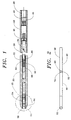
- the coating thickness measurement gauge 20 of the present invention includes an elongated tubular housing 22 which is generally in the shape of a pencil.
- a bore 24 extends completely through the housing 22 so that the housing 22 is open at opposite ends.
- the rearward end of the housing 22 i.e., the end to the right as seen in Fig. 1 includes an internal thread 26.
- the bore 24 that extends through the housing 22 includes a portion towards the rear of the housing 22 that is slightly larger in diameter than a portion of the bore located at the forward end of the housing 22.
- oppositely positioned narrowed portions 28, 29 are formed on the housing 22 adjacent the forward end of the housing 22.
- a measurement scale 30 is provided on one side of the housing 22 in the narrowed portion 28.
- the measurement scale 30 includes numerical markings which represent thicknesses in thousandths of an inch (mils).
- the housing 22 also includes a slot 34 that extends along the length of the narrowed portion 28. The slot 34 communicates with the interior of the housing 22 and the measurement scale 30 extends along the length of the slot 34.
- another measurement scale 32 is positioned on the opposite side of the housing 22 from the measurement scale 30.
- the scale 32 extends along the length of the narrowed portion 29.
- the measurement scale 32 includes numerical markings which represent thicknesses in millimeters.
- a slot 36 extends along the narrowed portion 29 and communicates with the interior of the housing 22.
- the measurement scale 32 extends along the length of the slot 36 and the slots 34, 36 are positioned opposite to one another.
- the gauge 20 further includes an elongated indicator rod 38 positioned within the tubular housing 22.
- a spring mounting member 40 is secured to the rear end of the indicator rod 38 in any suitable manner.
- a tension spring 42 is mounted on one end of the spring mounting member 40. The tension spring 42 exerts a biasing force on the indicator rod 38 in a direction toward the rear end of the housing 22 (i.e., toward the right as seen in Fig. 1).
- An adjustment screw 44 is positioned within the tubular housing 22 adjacent the rear end of the housing 22.
- a bore 45 extends completely through the adjustment screw 44.
- the tension spring 42 is connected to the adjustment screw 44.
- the outer peripheral surface of the adjustment screw 44 is threaded for threadably engaging the internal thread 26 at the rear end of the housing 22.
- the adjustment screw 44 is preferably provided with a suitably configured end face for permitting a screwdriver or the like to rotate the adjustment screw 44 along the rear portion of the housing 22.
- the tension spring 42 is secured to the adjustment screw 44 and the spring mounting member 40 in such a manner that rotation of the adjustment screw 44 results in rotation of and longitudinal movement of the indicator rod 38.
- the indicator rod 38 includes first and second tubular portions 46, 48 that are joined to one another by a tubular joining member 50.
- the first and second portions 46, 48 of the indicator rod may be differently colored in order to clearly identify the joining line 52.
- the joining line 52 serves as an indicating mark for indicating the thickness of the coating being measured during operation of the gauge 20.
- the indicator rod 38 that is utilized in the coating thickness measurement gauge of the present invention is specifically designed to take into account and compensate for the affect that the force of gravity has on the operation of the gauge 20.
- the indicator rod 38 in addition to the first indicating mark 52 defined by the joining line between the first and second tubular portions 46, 48 of the indicator rod 38, the indicator rod 38 also includes a second indicating mark 68 and a third indicating mark 70 located thereon.
- the second indicating mark 68 is positioned on the first portion 46 of the indicator rod 38 and is spaced from the first indicating mark 52 in a direction away from the forward end 51 of the housing 22.
- the third indicating mark 70 is positioned on the second portion 48 of the indicator rod 38 and is spaced from the first indicating mark 52 in a direction toward the forward end 51 of the housing 22.
- the second and third indicating marks 68, 70 are preferably spaced from the first indicating mark 52 by substantially equal distances.
- first and second tubular portions 46, 48 of the indicator rod 38 are preferably differently colored in order to result in a first indicating mark 52 that is clearly visible.
- the second and third indicating marks 68, 70 should also be suitably marked so that they are readily visible to the user.
- the second and third indicating marks 68, 70 can be marked by using differently colored fluorescent paint.
- the second and third indicating marks 68, 70 can be defined by colored grooves.
- the second indicating mark 68 may be colored green to signify that when the forward end 51 of the gauge is pointing downward (i.e., toward the grass) during a coating thickness measurement operation, the green indicating mark should be read.
- the third indicating mark can be colored blue to signify that when the forward end 51 of the gauge is pointing upward (i.e., toward the sky) during a coating thickness measurement operation, the blue indicating mark should be read.
- a probe assembly 54 is mounted at the forward end of the second portion 48 of the indicator rod 38.
- the probe assembly 54 includes a tubular casing 56 and a spherical contact member 58 mounted at the forward end of the casing 56.
- the casing 56 is preferably formed of a relatively non-magnetizable material such as brass.
- the rearward portion of the casing 56 is provided with an internal thread 62.
- the contact member 58 may be a sphere of cemented carbide, possibly tungsten carbide, containing from about 5 to 30 weight percent cobalt (or equivalent metal) binder or a sphere of a particular alloy of aluminum, iron, and silicon commercially known as Alfesil (Low Wear Material).
- the contact member 58 is preferably spherical, primarily for economical reasons. By providing the contact member as a sphere, a desired spherical contact surface is provided so as to permit a point contact for the probe assembly. Moreover, the spherical contact member does not require a costly and complex machining operation.
- the spherical contact member 58 may be readily secured at the forward end of the casing 56 in any suitable manner such as by providing an annular support shoulder 60 on the inner surface of the casing 56 and by inwardly turning the forward end of the casing to press fit the spherical contact member 58 in place.
- suitable arrangements can be provided for properly seating and securing the spherical member 58 at the forward end of the casing 56.
- the set-screw 65 is preferably fabricated of ferrous material such as steel or a steel alloy so as to be releasably attached to the magnet 64 by magnetic attraction. Alternatively, the set-screw 65 can be secured to the magnet 65 in a permanent manner.
- the external thread on the set-screw threadably engages the internal thread 62 on the interior of the casing 56 as well as an internal thread 49 at the forward end of the second tubular portion 48 of the indicator rod 38.
- the set-screw 65 serves to connect the probe assembly 54 to the forward end of the indicator rod 38.
- the end of the set-screw 65 located farthest from the spherical contact member 58 is suitably configured to permit a screwdriver of the like to cooperate therewith in order to rotate and longitudinally adjust the position of the set-screw 65.
- a screwdriver of the like By rotating the set-screw 65, the position of the magnet 64 relative to the spherical contact member 58 can be varied.
- the position of the set-screw 65 and the magnet 64 can be adjusted by inserting the screwdriver or other adjustment instrument through the bore 45 in the adjustment screw 44, through the tension spring 42, and through the tubular indicator rod 38.
- the magnet 64 utilized in the coating thickness measurement gauge of the present invention differs from magnets used in known gauges in that a portion of the light rare earth element or elements is replaced with one or more heavy rare earth elements.
- the magnet of the present invention is fabricated from a combination of one or more light rare earth elements and one or more heavy rare earth elements.
- the magnets are of the (RE)(TM)5 type or the (RE)2(TM)17 where the term (RE) is a combination of light and heavy rare earth elements and the term (TM) is a transition element or elements in the atomic ratios of 1:5 or 2:17.
- the light rare earth elements utilized in fabricating the magnet 64 of the present invention include samarium, praseodymium, neodymium, yttrium, cerium, and lanthanum.
- the heavy rare earth elements preferably include europium, gadolinium, terbium, dysprosium, holmium, erbium, thulium, ytterbium and lutetium.
- the transition element can be manganese, iron, cobalt, nickel, or copper.
- the (RE)(TM)5 can be a composition of (Sm0.5Gd 0.5 )(CO)5.
- variations of that composition can include all compositions between (Sm 0.25 Gd 0.75 )(CO)5 and (Sm 0.75 Gd 0.25 )(CO)5.
- compositions can also be utilized in the 2:17 system mentioned above.
- a composition of (Sm 1.0 Gd 1.0 )(Co)17 may be utilized.
- variations on that composition can include all compositions between (Sm 0.5 Gd 1.5 )(Co)17 and (Sm 1.5 Gd 0.5 )(Co)17, where the (Co)17 is nominally (Co .67 Fe .23 Cu .08 Zr .02 )17.
- compositions have been given by way of example and it is to be understood that the magnet according to the present invention can be fabricated from a composition that includes more than one type of light rare earth element as well as more than one type of heavy rare earth element. Also, compositions other than the 1:5 and 2:17 systems mentioned above may be employed if desired.
- the coating thickness measurement gauge of the present invention is able to accurately measure the thickness of coatings over a wide range of temperatures.
- the magnetic strength of the elements can vary by an amount plus or minus 4% per 100°C change in temperature, thereby resulting in similar variations in the measurements obtained.
- Errors which result from the temperature of the substrate being greater than or less than room temperature can be reduced to less than 1% and, in some cases, less than 1/2% per 100°C when utilizing a magnet in accordance with the present invention.
- the coating thickness measurement gauge of the present invention permits the accurate measurement of coating thicknesses when the temperature of the substrate is from about -100°C up to about +300°C.
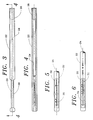
- the coating thickness measurement gauge 20 of the present invention it is first necessary to determine whether the gauge requires calibration. To make that determination, the gauge 20 is held in the horizontal position and the adjustment screw 44 is rotated by way of a screwdriver or other adjustment tool until the first indicating mark 52 comes into alignment with an end line 31 (see Fig. 6) on the measurement scale. The contact member 58 is positioned in engagement with a horizontally oriented calibration surface having a coating of either a known thickness or of no thickness at all. The housing 22 is then slowly pulled away from the calibration surface and at the same time, the first indicating mark 52 is observed through one of the slots 34, 36.
- the position of the first indicating mark 52 at the point when the contact member 58 moves out of engagement with the calibration surface is noted. If the thickness read on the appropriate measurement scale as indicated by the position of the first indicating mark 52 differs from the known thickness of the coating on the calibration surface, the gauge must be calibrated.
- a screwdriver or other adjustment instrument is inserted from the rear end of the gauge 20, through the bore 45 in the adjustment screw 44, through the tension spring 42, and through the tubular indicator rod 38 in order to rotate the set-screw 65 and adjust the position of the magnet 64 relative to the contact member. If the measured thickness of the coating on the calibration surface as determined from the above-described operation is less than the known thickness, the set-screw 65 is rotated in the manner necessary for moving the magnet 64 away from the contact member 58. On the other hand, if the measured thickness of the coating on the calibration surface is greater than the known thickness, the set-screw 65 is rotated to effect movement of the magnet 64 toward the contact member 58. The foregoing calibration procedure is continued until the measured thickness of the coating on the calibration surface corresponds to the known thickness.
- the gauge Upon completion of the calibration procedure, the gauge is ready for measuring the thickness of a coating.
- the gauge 20 To measure the thickness of a non-magnetic coating on a ferromagnetic substrate, the gauge 20 is held in the horizontal position and the first indicating mark 52 is brought into alignment with the end line 31 on the measurement scale 30. The contact member 58 is then positioned on the coating to be measured and the housing is slowly pulled away from the coating. If the coating being measured is located on a vertically oriented member so that the gauge 20 is horizontally positioned, the first indicating mark 52 is observed through one of the slots 34, 36 as the housing is pulled away from the coating.
- the position of the first indicating mark 52 is noted.
- the thickness of the coating can then be read from either measurement scale 30, 32 as indicated by the noted position of the first indicating mark 52.
- the second indicating mark 68 is observed through one of the slots 34, 36 as the housing 22 is being pulled away from the coating.
- the biasing force of the tension spring 42 overcomes the force of magnetic attraction so that the contact member 58 moves out of engagement with the coating, the position of the second indicating mark 68 is noted.
- the thickness of the coating can then be read from either measurement scale 30, 32 as indicated by the noted position of the second indicating mark 68.
- the third indicating mark 70 is observed through one of the slots 34, 36 as the housing 22 is being pulled away from the coating.
- the biasing force of the tension spring 42 overcomes the magnetic attraction force so that the contact member 58 moves out of engagement with the coating, the position of the third indicating mark 70 is noted.
- the thickness of the coating can then be read from either measurement scale 30, 32 as indicated by the noted position of the third indicating mark 70.
- the coating thickness measurement gauge 20 of the present invention is able to compensate for the affect that gravity has on the operation of the gauge when measuring in different positions due to the presence of the first, second, and third indicating marks 52, 68, 70 on the indicator rod 38.
- the force of gravity acts with the magnetic attraction force, thereby requiring a larger force to move the contact member 58 out of engagement with the coating.
- the second indicating mark 68 i.e., if the thickness were measured with the first indicating mark 52
- the measured thickness would be less than the actual thickness of the coating.
- the gauge of the present invention compensates for that inaccuracy by providing a second indicating mark 68 that is spaced from the first indicating mark 52 in a direction away from the probe assembly 54.
- the second indicating mark 68 is spaced from the first indicating mark 52 by a distance that corresponds substantially to the additional amount of force that is necessary to move the contact member out of engagement with the coating as a result of the force of gravity.
- that distance has been determined to be approximately one millimeter. That distance may vary depending upon, for example, the weight of the various parts of the gauge.
- the gauge 20 When the gauge 20 is vertically positioned with the forward end 51 of the gauge directed upward, the force of gravity acts in opposition to the force of magnetic attraction, thereby requiring a smaller force to move the contact member 58 out of engagement with the coating.
- the measured thickness In the absence of the third indicating mark 70 (i.e., if the thickness were measured with the first indicating mark 52), the measured thickness would be greater than the actual thickness of the coating.
- the gauge of the present invention compensates for that inaccuracy by providing a third indicating mark 70 that is spaced from the first indicating mark 52 in a direction toward the probe assembly 54.
- the third indicating mark 70 is spaced from the first indicating mark 52 by a distance that corresponds substantially to the amount by which the force necessary for moving the contact member out of engagement with the coating is reduced due to the force of gravity. In the gauge of the present invention, that distance has been determined to be approximately one millimeter. As noted above, that distance may vary.
- the first indicating mark 52 can be used to indicate the thickness of the coating.
- the coating thickness measurement gauge according to the present invention has been described as including the gravity compensating feature in combination with the magnet fabricated from a combination of heavy and light rare earth elements, it is to be understood that those two features can be used independently of one another.
- the gravity compensating feature can be employed in a magnetic coating thickness measurement gauge without the magnet described above.
- the indicating marks 52, 68, 70 are located on the indicator rod 38 while the measurement scales 30, 32 are located on the housing 22. It should be apparent that that arrangement could be reversed with the measurement scales 30, 32 being located on the indicator rod 38 and the indicating marks 52, 68, 70 being positioned on the housing 22.
- the magnet and gravity compensating feature described above can be used in conjunction with coating thickness measurement gauges other than the one described above.
- the use of the magnet of the present invention in a gauge similar to the one described above which only requires a single point contact with the coating does provide an additional advantage above and beyond those noted above.
- it may not be possible to use known types of gauges which have supports or foot pads that rest on the coating surface during the measurement operation see, for example, U.S. Patent No. 4,733,178) because such supports or foot pads may not be able to withstand the temperature of the substrate.
- the gauge of the present invention as described above only requires one point engagement of the contact member with the coating, those problems do not arise, regardless of the temperature of the substrate.
- the use of a magnet fabricated from a composition of light and heavy rare earth elements in combination with the gauge described above not only produces accurate thickness measurements when the substrate is significantly above room temperature but in addition, permits coating thickness measurements on hot substrates to be obtained without causing damage to the gauge.
Landscapes
- Physics & Mathematics (AREA)
- General Physics & Mathematics (AREA)
- Measurement Of Length, Angles, Or The Like Using Electric Or Magnetic Means (AREA)
- A Measuring Device Byusing Mechanical Method (AREA)
- Testing Or Measuring Of Semiconductors Or The Like (AREA)
- Length Measuring Devices By Optical Means (AREA)
- Length Measuring Devices With Unspecified Measuring Means (AREA)
Claims (9)
- Meßinstrument zum Bestimmen der Dicke einer Beschichtung auf einer ferromagnetischen Unterlage, umfassend:(a) ein rohrförmiges Gehäuse (22), das ein erstes Ende und ein entgegengesetzt positioniertes zweites Ende hat, wobei das Gehäuse (22) ein Inneres (24) hat;(b) einen Stab (38), der beweglich innerhalb des Inneren (24) des Gehäuses (22) positioniert ist, wobei der Stab (38) ein vorderes Ende und ein rückwärtiges Ende hat;(c) ein Magnetmittel (64), das an dem vorderen Ende des Stabs (38) zum Vorsehen einer magnetischen Anziehungskraft angebracht ist, welche den Stab (38) nach der Beschichtung zu aufgrund der darunterliegenden ferromagnetischen Unterlage drängt, um das Magnetmittel (64) in Eingriff mit der Beschichtung zu bringen;(d) ein Federmittel (42) das wirksam mit dem Gehäuse (22) und dem Stab (38) zum Erzeugen einer Vorspannungskraft, die entgegengesetzt zu der Kraft der magnetischen Anziehung ist, verbunden ist;(e) eine die Beschichtungsdicke angebende Dickenmeßskala (30, 32), welche sich längs eines Teils des Gehäuses (22) erstreckt; und(f) ein Anzeigemittel (52, 68, 70) zum Anzeigen der Dicke der Beschichtung im Zusammenwirken mit der Meßskala (30, 32),dadurch gekennzeichnet, daß das Anzeigemittel (52, 68, 70) umfaßt(1) einen ersten Indikator (52), welcher derart vorgesehen ist, daß er im Zusammenwirken mit der Dickenmeßskala (30, 32) die Dicke der Beschichtung anzeigt, wenn die Kraft der magnetischen Anziehung im wesentlichen senkrecht zu der Richtung der Schwerkraft ist;(2) einen zweiten Indikator (68), welcher derart vorgesehen ist, daß er im Zusammenwirken mit der Meßskala (30, 32) die Dicke der Beschichtung anzeigt, wenn die Kraft der magnetischen Anziehung im wesentlichen parallel zu der und in der gleichen Richtung wie die Schwerkraft ist; und(3) einen dritten Indikator (70), welcher derart vorgesehen ist, daß er im Zusammenwirken mit der Meßskala (30, 32) die Dicke der Beschichtung anzeigt, wenn die Kraft der magnetischen Anziehung im wesentlichen parallel zu der und in der Richtung entgegengesetzt zu der Schwerkraft ist.
- Meßinstrument gemäß Anspruch 1, dadurch gekennzeichnet, daß das Gehäuse (22) einen Schlitz (34, 36) hat, der sich längs eines Teils des Gehäuses (22) benachbart dem ersten Ende erstreckt, wobei der Schlitz (34, 36) in Verbindung mit dem Inneren (24) des Gehäuses (22) ist, wobei das Gehäuse (22) die Dickenmeßskala (30, 32) hat, welche sich längs des Schlitzes (34, 36) und benachbart dem Schlitz (34, 36) erstreckt; und der erste, zweite und dritte Indikator (52, 68, 70) auf dem Stab (38) angeordnet und durch den Schlitz (34, 36) sichtbar sind.
- Meßinstrument gemäß Anspruch 2, dadurch gekennzeichnet, daß der erste Indikator eine erste Anzeigemarkierung (52) auf dem Anzeigestab (38) umfaßt, der zweite Indikator eine zweite Anzeigemarkierung (68) auf dem Anzeigestab (38) umfaßt, wobei die zweite Anzeigemarkierung (68) von der ersten Anzeigemarkierung (52) unterscheidbar und von der ersten Anzeigemarkierung (52) in einer Richtung weg von dem Magnetmittel (64) beabstandet ist, der dritte Indikator eine dritte Anzeigemarkierung (70) auf dem Anzeigestab (38) umfaßt, die von der ersten Anzeigemarkierung (52) in einer Richtung nach dem Magnetmittel (64) zu beabstandet ist.
- Meßinstrument gemäß Anspruch 3, dadurch gekennzeichnet, daß das Federmittel eine Spannfeder (42) ist, die ein Ende hat, das auf einem Federanbringungsteil (40) angebracht ist, wobei das Federanbringungsteil (40) mit dem rückwärtigen Ende des Anzeigestabs (38) verbunden ist.
- Meßinstrument gemäß Anspruch 4, dadurch gekennzeichnet, daß ein entgegengesetztes Ende der Spannfeder (42) auf einer Einstellschraube (44) zum Einstellen der Position des Anzeigestabs (38) innerhalb des Gehäuses (22) angebracht ist, wobei die Einstellschraube (44) eine mit Gewinde versehene äußere Umfangsoberfläche hat, die in Eingriff ist mit einem mit Innengewinde versehenen Teil (26) in dem Inneren des Gehäuses (22) benachbart einem zweiten Ende des Gehäuses (22), welches entgegengesetzt dem ersten Ende ist.
- Meßinstrument gemäß Anspruch 5, dadurch gekennzeichnet, daß das Magnetmittel (64) mit einer mit Außengewinde versehenen Anbringungsschraube (65) verbunden ist, wobei das Außengewinde auf der Anbringungsschraube (65) in Schraubeingriff mit einem mit Innengewinde versehenen Teil (49) an dem vorderen Ende des Anzeigestabs (38) ist, und umfassend ein Halteteil (56), das ein sphärisch geformtes ferromagnetisches Kontaktteil (58) hat, welches an einem vorderen Ende desselben angebracht ist, wobei ein rückwärtiges Ende (62) des Halteteils (56) mit Innengewinde versehen ist und in Schraubeingriff mit dem Außengewinde auf der Anbringungsschraube (65) ist, so daß das Halteteil (56) mit dem vorderen Ende des Anzeigestabs (38) verbunden ist und so daß der Magnet (64) innerhalb des Halteteils (56) positioniert ist.
- Meßinstrument gemäß Anspruch 6, dadurch gekennzeichnet, daß die Einstellschraube (44) und der Anzeigestab (38) eine Bohrung (45) haben, die sich dadurch erstreckt, um zur Einstellung der Position des Magneten (64) relativ zu dem sphärischen Kontaktteil (58) Zugang zu der Anbringungsschraube (65) von dem zweiten Ende des Gehäuses (22) her zu ermöglichen.
- Meßinstrument gemäß irgendeinem der Ansprüche 1 bis 7, dadurch gekennzeichnet, daß das Magnetmittel (64) aus einer Kombination von wenigstens einem leichten Seltene-Erde-Element und wenigstens einem schweren Seltene-Erde-Element hergestellt ist, worin das wenigstens eine schwere Seltene-Erde-Element eine Ordnungszahl von wenigstens 63 hat und das wenigsens eine leichte Seltene-Erde-Element eine Ordhungszahl von weniger als 63 hat.
- Verfahren zum Bestimmen der Dicke einer Beschichtung auf einer ferromagnetischen Unterlage durch die Verwendung eines Meßinstruments (20), welches ein Gehäuse (22), das ein Inneres (24) und eine Öffnung hat, einen Stab (38), der bewegbar innerhalb des Inneren (24) des Gehäuses (22) positioniert ist, ein Sondenmittel (54), das auf einem vorderen Ende des Stabs (38) angebracht und dazu geeignet ist, sich durch die Öffnung in dem Gehäuse (22) zum Erzeugen einer magnetischen Anziehungskraft, welche den Stab (38) nach der Beschichtung zu aufgrund des Vorhandenseins der darunterliegenden ferromagnetischen Unterlage drängt, zu erstrecken, und eine Feder (42), die wirksam mit dem Gehäuse (22) und dem Stab (38) zum Vorsehen einer Vorspannungskraft, die entgegengesetzt zu der magnetischen Anziehungskraft ist, umfaßt, wobei das Verfahren die Schritte umfaßt:(a) Ineingriffbringen des Sondenmittels (54) mit der Beschichtung; und(b) Wegziehen des Gehäuses (22) von der Beschichtung, bis sich das Sondenmittel (54) außer Eingriff mit der Beschichtung bewegt,worin das Meßinstrument ein Skalenmittel (30, 32) in der Form von numerischen Indices und ein Anzeigemittel (52, 68, 70) zum Angeben der Beschichtungsdicke basierend auf dem Betrag der Bewegung des Stabs (38) relativ zu dem Gehäuse (22) umfaßt;
dadurch gekennzeichnet, daß das Anzeigemittel (52, 68, 70) einen ersten Indikator (52), einen zweiten Indikator (68) und einen dritten Indikator (70) zum Anzeigen der Dicke der Beschichtung im Zusammenwirken mit dem Skalenmittel (30, 32) umfaßt,
wobei das Verfahren das Bestimmen der Dicke der Beschichtung an dem Punkt, wenn sich das Sondenmittel (54) außer Eingriff mit der Beschichtung bewegt, durch Ablesen der Dicke auf dem Skalenmittel auf dem Skalenmittel (30, 32) umfaßt, die fluchtet mit(1) dem ersten Indikator (52), wenn die Kraft der magnetischen Anziehung im wesentlichen senkrecht zu der Richtung der Schwerkraft ist,(2) dem zweiten Indikator (68), wenn die Kraft der magnetischen Anziehung im wesentlichen parallel zur und in der Richtung der Schwerkraft ist, oder(3) dem dritten Indikator (70), wenn die Kraft der magnetischen Anziehung im wesentlichen parallel zu der und in einer Richtung entgegengesetzt zu der Schwerkraft ist.
Applications Claiming Priority (2)
| Application Number | Priority Date | Filing Date | Title |
|---|---|---|---|
| US599101 | 1990-10-17 | ||
| US07/599,101 US5094009A (en) | 1990-10-17 | 1990-10-17 | Gauge for measuring the thickness of a coating on a substrate |
Publications (2)
| Publication Number | Publication Date |
|---|---|
| EP0481334A1 EP0481334A1 (de) | 1992-04-22 |
| EP0481334B1 true EP0481334B1 (de) | 1995-03-29 |
Family
ID=24398222
Family Applications (1)
| Application Number | Title | Priority Date | Filing Date |
|---|---|---|---|
| EP91117145A Expired - Lifetime EP0481334B1 (de) | 1990-10-17 | 1991-10-08 | Dickenmessgerät zum Messen der auf einem Substrat liegenden Schicht |
Country Status (4)
| Country | Link |
|---|---|
| US (1) | US5094009A (de) |
| EP (1) | EP0481334B1 (de) |
| AT (1) | ATE120541T1 (de) |
| DE (1) | DE69108504T2 (de) |
Families Citing this family (11)
| Publication number | Priority date | Publication date | Assignee | Title |
|---|---|---|---|---|
| US5343146A (en) * | 1992-10-05 | 1994-08-30 | De Felsko Corporation | Combination coating thickness gauge using a magnetic flux density sensor and an eddy current search coil |
| US5327659A (en) * | 1992-12-03 | 1994-07-12 | R. R. Donnelley & Sons Co. | Wet film thickness gauge |
| US6575115B2 (en) * | 1999-02-22 | 2003-06-10 | Ray Keith Lake | Thickness gauge pin |
| DE19918064C2 (de) * | 1999-04-21 | 2003-09-18 | Norbert Nix | Schichtdickenmeßgerät mit automatisierter Nulleinstellung und/oder Kalibrierung |
| US7406773B2 (en) * | 2004-12-23 | 2008-08-05 | Irwin Industrial Tool Company | Magnet assembly |
| US8229523B2 (en) * | 2008-05-27 | 2012-07-24 | Nokia Corporation | Locking mechanism |
| US20100171493A1 (en) * | 2009-01-07 | 2010-07-08 | Robert Standen | Method and device for measuring thickness of a substrate |
| US8448596B2 (en) * | 2010-06-02 | 2013-05-28 | Valentine International Ltd. | Device for sensing gap variation |
| US9304073B2 (en) * | 2013-02-05 | 2016-04-05 | Pilkington Group Limited | Bond strength testing apparatus and method for using same |
| US9518812B2 (en) | 2015-01-16 | 2016-12-13 | Schlage Lock Company Llc | Self-adjusting door thickness indicator |
| CN113959390B (zh) * | 2021-11-05 | 2024-02-09 | 扬州中远海运重工有限公司 | 一种远距离测膜标记用的一体支架 |
Family Cites Families (22)
| Publication number | Priority date | Publication date | Assignee | Title |
|---|---|---|---|---|
| US2625585A (en) * | 1949-12-01 | 1953-01-13 | Glen N Krouse | Magnetic measuring gauge |
| US2749505A (en) * | 1952-11-22 | 1956-06-05 | Mcnary Forrest Cline | Apparatus for gaging |
| GB799768A (en) * | 1954-10-13 | 1958-08-13 | Jaroslav Binko | Apparatus for measuring the thickness of non-magnetic layers on a magnetic base material |
| AT215169B (de) * | 1958-12-09 | 1961-05-25 | Vaclav Ing Bruna | Gerät zur Bestimmung der Dicke nicht magnetisierbarer Schichten auf ferromagnetischen Prüflingen |
| GB907721A (en) * | 1958-12-22 | 1962-10-10 | Vaclav Bruna | Instrument for use in measuring the thickness of a non-metallic layer on a ferro-magnetic base material |
| DE2107076C3 (de) * | 1971-02-15 | 1975-01-30 | Elektro-Physik Hans Nix & Dr.-Ing. E. Steingroever Kg, 5000 Koeln | Magnetischer Schicht-Dickenmesser |
| US3901741A (en) * | 1973-08-23 | 1975-08-26 | Gen Electric | Permanent magnets of cobalt, samarium, gadolinium alloy |
| US4160208A (en) * | 1976-01-27 | 1979-07-03 | Elektro-Physik, Hans Nix & Dr. -Ing E. Steingroever Kg. | Method of calibrating magnetic thickness gauges |
| JPS52109191A (en) * | 1976-03-10 | 1977-09-13 | Toshiba Corp | Permanent magnet |
| DE2630099C2 (de) * | 1976-07-03 | 1985-09-19 | Elektro-Physik Hans Nix & Dr.-Ing. E. Steingroever KG, 5000 Köln | Magnetischer Schichtdickenmesser |
| SU590591A1 (ru) * | 1976-11-18 | 1978-01-30 | Белоярская атомная электростанция им.И.В.Курчатова | Толщиномер |
| DE2855912C2 (de) * | 1978-12-23 | 1988-08-18 | Nix, Norbert, Dr., 5000 Köln | Einrichtung zur Messung der Dicke von festen Überzügen auf einem Grundmaterial |
| US4226620A (en) * | 1979-04-27 | 1980-10-07 | The United States Of America As Represented By The Secretary Of The Army | Magnetic alloys |
| US4392305A (en) * | 1980-07-08 | 1983-07-12 | Elektro-Physik Hans Nix & Dr. Ing. E. Steingroever, K.G. | Pencil shaped magnetic coating thickness gauge |
| US4433290A (en) * | 1981-11-12 | 1984-02-21 | Defelsko Corporation | Magnetic coating thickness comparator having parallel magnetic rods with nonmagnetic slide indicators |
| US4567436A (en) * | 1982-01-21 | 1986-01-28 | Linda Koch | Magnetic thickness gauge with adjustable probe |
| US4733178A (en) * | 1982-01-21 | 1988-03-22 | Linda Koch | Magnetic thickness gauge with third support |
| US4599562A (en) * | 1983-11-07 | 1986-07-08 | Defelsko Corporation | Method and apparatus for magnetically measuring a coating with a plurality of magnets |
| DE3401466A1 (de) * | 1984-01-18 | 1985-07-25 | Elektro-Physik Hans Nix & Dr.-Ing. E. Steingroever KG, 5000 Köln | Sonde fuer die kontinuierliche messung der dicke von schichten oder baendern |
| US4634974A (en) * | 1985-01-31 | 1987-01-06 | Hunter Rudolf A | Device including moveable shaft and magnet for sensing magnetic metal |
| DE3611798A1 (de) * | 1985-12-13 | 1987-06-19 | Max Hacklinger | Dickenmessgeraet |
| US5006799A (en) * | 1988-12-01 | 1991-04-09 | Pfanstiehl John G | Low cost magnetic coating thickness gauge with holding magnet, bias spring and holding force indicator |
-
1990
- 1990-10-17 US US07/599,101 patent/US5094009A/en not_active Expired - Fee Related
-
1991
- 1991-10-08 AT AT91117145T patent/ATE120541T1/de not_active IP Right Cessation
- 1991-10-08 DE DE69108504T patent/DE69108504T2/de not_active Expired - Fee Related
- 1991-10-08 EP EP91117145A patent/EP0481334B1/de not_active Expired - Lifetime
Also Published As
| Publication number | Publication date |
|---|---|
| ATE120541T1 (de) | 1995-04-15 |
| EP0481334A1 (de) | 1992-04-22 |
| DE69108504T2 (de) | 1995-09-21 |
| DE69108504D1 (de) | 1995-05-04 |
| US5094009A (en) | 1992-03-10 |
Similar Documents
| Publication | Publication Date | Title |
|---|---|---|
| US5094009A (en) | Gauge for measuring the thickness of a coating on a substrate | |
| US5006799A (en) | Low cost magnetic coating thickness gauge with holding magnet, bias spring and holding force indicator | |
| US4567436A (en) | Magnetic thickness gauge with adjustable probe | |
| US2625585A (en) | Magnetic measuring gauge | |
| US4327493A (en) | Method and apparatus for measurement of distance between holes with parallel axes | |
| US5109609A (en) | Ball-point surface checking device and method | |
| US5319860A (en) | Measuring instrument | |
| US2364237A (en) | Electrical caliper | |
| US3382582A (en) | Magnetic indicating square | |
| US4433290A (en) | Magnetic coating thickness comparator having parallel magnetic rods with nonmagnetic slide indicators | |
| EP0028487A1 (de) | Dickenmessgerät mit Hall-Effekt | |
| US5286147A (en) | Depth gage adapter | |
| EP0431975A1 (de) | Wandler mit variabler Induktanz | |
| US4738131A (en) | Guarded ring tensioned thickness standard | |
| Frantz et al. | Specifying 3D tracking system accuracy one manufacturer’s views | |
| US4160208A (en) | Method of calibrating magnetic thickness gauges | |
| US3740998A (en) | Method for calibrating instruments designed to gauge the thickness ofnonmagnetic coatings on metal products and attachment for the realization of this method | |
| Brenner | Magnetic Method for Measuring the Thickness of Nonmagnetic Coatings on Iron and Steel | |
| EP0093772A1 (de) | Vergleichsanordnung zwischen der dicke einer beschichtung und der oberflächenrauheit | |
| Wenzler¹ et al. | Measurement of film thickness | |
| Sajdera | Thickness testing | |
| Sajdera | Thickness testing | |
| JPH08152303A (ja) | 膜厚計用プローブ | |
| Sajdera | Thickness testing | |
| SU947633A1 (ru) | Магнитный способ измерени покрытий и устройство дл его осуществлени |
Legal Events
| Date | Code | Title | Description |
|---|---|---|---|
| PUAI | Public reference made under article 153(3) epc to a published international application that has entered the european phase |
Free format text: ORIGINAL CODE: 0009012 |
|
| AK | Designated contracting states |
Kind code of ref document: A1 Designated state(s): AT BE CH DE DK ES FR GB GR IT LI LU NL SE |
|
| 17P | Request for examination filed |
Effective date: 19920924 |
|
| 17Q | First examination report despatched |
Effective date: 19931123 |
|
| GRAA | (expected) grant |
Free format text: ORIGINAL CODE: 0009210 |
|
| AK | Designated contracting states |
Kind code of ref document: B1 Designated state(s): AT BE CH DE DK ES FR GB GR IT LI LU NL SE |
|
| PG25 | Lapsed in a contracting state [announced via postgrant information from national office to epo] |
Ref country code: IT Free format text: LAPSE BECAUSE OF FAILURE TO SUBMIT A TRANSLATION OF THE DESCRIPTION OR TO PAY THE FEE WITHIN THE PRE;WARNING: LAPSES OF ITALIAN PATENTS WITH EFFECTIVE DATE BEFORE 2007 MAY HAVE OCCURRED AT ANY TIME BEFORE 2007. THE CORRECT EFFECTIVE DATE MAY BE DIFFERENT FROM THE ONE RECORDED.SCRIBED TIME-LIMIT Effective date: 19950329 Ref country code: DK Effective date: 19950329 Ref country code: CH Effective date: 19950329 Ref country code: GR Free format text: LAPSE BECAUSE OF FAILURE TO SUBMIT A TRANSLATION OF THE DESCRIPTION OR TO PAY THE FEE WITHIN THE PRESCRIBED TIME-LIMIT Effective date: 19950329 Ref country code: FR Effective date: 19950329 Ref country code: LI Effective date: 19950329 Ref country code: BE Effective date: 19950329 Ref country code: NL Free format text: LAPSE BECAUSE OF NON-PAYMENT OF DUE FEES Effective date: 19950329 Ref country code: ES Free format text: THE PATENT HAS BEEN ANNULLED BY A DECISION OF A NATIONAL AUTHORITY Effective date: 19950329 Ref country code: AT Effective date: 19950329 |
|
| REF | Corresponds to: |
Ref document number: 120541 Country of ref document: AT Date of ref document: 19950415 Kind code of ref document: T |
|
| REF | Corresponds to: |
Ref document number: 69108504 Country of ref document: DE Date of ref document: 19950504 |
|
| PG25 | Lapsed in a contracting state [announced via postgrant information from national office to epo] |
Ref country code: SE Effective date: 19950629 |
|
| REG | Reference to a national code |
Ref country code: CH Ref legal event code: PL |
|
| EN | Fr: translation not filed | ||
| NLV1 | Nl: lapsed or annulled due to failure to fulfill the requirements of art. 29p and 29m of the patents act | ||
| PG25 | Lapsed in a contracting state [announced via postgrant information from national office to epo] |
Ref country code: LU Free format text: LAPSE BECAUSE OF NON-PAYMENT OF DUE FEES Effective date: 19951031 |
|
| PLBE | No opposition filed within time limit |
Free format text: ORIGINAL CODE: 0009261 |
|
| STAA | Information on the status of an ep patent application or granted ep patent |
Free format text: STATUS: NO OPPOSITION FILED WITHIN TIME LIMIT |
|
| 26N | No opposition filed | ||
| PGFP | Annual fee paid to national office [announced via postgrant information from national office to epo] |
Ref country code: GB Payment date: 20011010 Year of fee payment: 11 |
|
| PGFP | Annual fee paid to national office [announced via postgrant information from national office to epo] |
Ref country code: DE Payment date: 20011022 Year of fee payment: 11 |
|
| REG | Reference to a national code |
Ref country code: GB Ref legal event code: IF02 |
|
| PG25 | Lapsed in a contracting state [announced via postgrant information from national office to epo] |
Ref country code: GB Free format text: LAPSE BECAUSE OF NON-PAYMENT OF DUE FEES Effective date: 20021008 |
|
| PG25 | Lapsed in a contracting state [announced via postgrant information from national office to epo] |
Ref country code: DE Free format text: LAPSE BECAUSE OF NON-PAYMENT OF DUE FEES Effective date: 20030501 |
|
| GBPC | Gb: european patent ceased through non-payment of renewal fee |
Effective date: 20021008 |