EP0481393A2 - Système de commande hydraulique pour une transmission automatique de véhicule - Google Patents
Système de commande hydraulique pour une transmission automatique de véhicule Download PDFInfo
- Publication number
- EP0481393A2 EP0481393A2 EP91117467A EP91117467A EP0481393A2 EP 0481393 A2 EP0481393 A2 EP 0481393A2 EP 91117467 A EP91117467 A EP 91117467A EP 91117467 A EP91117467 A EP 91117467A EP 0481393 A2 EP0481393 A2 EP 0481393A2
- Authority
- EP
- European Patent Office
- Prior art keywords
- pressure
- oil
- engagement element
- port
- speed stage
- Prior art date
- Legal status (The legal status is an assumption and is not a legal conclusion. Google has not performed a legal analysis and makes no representation as to the accuracy of the status listed.)
- Granted
Links
- 230000005540 biological transmission Effects 0.000 title claims abstract description 100
- 238000003825 pressing Methods 0.000 claims description 4
- 230000035939 shock Effects 0.000 abstract description 21
- 230000009467 reduction Effects 0.000 abstract description 6
- 230000008859 change Effects 0.000 description 12
- 230000007423 decrease Effects 0.000 description 6
- 238000010586 diagram Methods 0.000 description 5
- 230000004913 activation Effects 0.000 description 4
- 230000000994 depressogenic effect Effects 0.000 description 4
- XDDAORKBJWWYJS-UHFFFAOYSA-N glyphosate Chemical compound OC(=O)CNCP(O)(O)=O XDDAORKBJWWYJS-UHFFFAOYSA-N 0.000 description 4
- 230000001133 acceleration Effects 0.000 description 3
- 230000009471 action Effects 0.000 description 2
- 230000004075 alteration Effects 0.000 description 1
- 238000002485 combustion reaction Methods 0.000 description 1
- 239000000498 cooling water Substances 0.000 description 1
- 230000000881 depressing effect Effects 0.000 description 1
- 238000006073 displacement reaction Methods 0.000 description 1
- 230000002349 favourable effect Effects 0.000 description 1
- 230000000116 mitigating effect Effects 0.000 description 1
- 230000004048 modification Effects 0.000 description 1
- 238000012986 modification Methods 0.000 description 1
- 230000000630 rising effect Effects 0.000 description 1
- 238000011144 upstream manufacturing Methods 0.000 description 1
Images



Classifications
-
- F—MECHANICAL ENGINEERING; LIGHTING; HEATING; WEAPONS; BLASTING
- F16—ENGINEERING ELEMENTS AND UNITS; GENERAL MEASURES FOR PRODUCING AND MAINTAINING EFFECTIVE FUNCTIONING OF MACHINES OR INSTALLATIONS; THERMAL INSULATION IN GENERAL
- F16H—GEARING
- F16H61/00—Control functions within control units of change-speed- or reversing-gearings for conveying rotary motion ; Control of exclusively fluid gearing, friction gearing, gearings with endless flexible members or other particular types of gearing
- F16H61/04—Smoothing ratio shift
- F16H61/06—Smoothing ratio shift by controlling rate of change of fluid pressure
- F16H61/065—Smoothing ratio shift by controlling rate of change of fluid pressure using fluid control means
Definitions
- the present invention relates to a hydraulic control device for an automatic automotive transmission system which automatically and hydraulically controls the shifting of the speed stages of an automatic transmission system suitable for use in motor vehicles in general.
- automatic transmission systems are widely used in automotive vehicles so that the shifting operation of the transmission may be hydraulically controlled, and there are those which carry out an transmission operation according to the vehicle speed and the throttle opening serving as a parameter representing the engine load according to prescribed transmission characteristics.
- the shock due to the abrupt change in the transmitted torque can be mitigated by appropriately increasing the rotational speed of the engine according to the gear ratio of the low speed stage and synchronizing the gears that are about to be meshed with each other.
- 61-84450 teaches a similar ejection valve which is placed in an oil ejection passage for an hydraulic engagement element for a high speed stage and is provided with a valve member which is displaced so as to open the oil ejection passage either by the supply pressure of a hydraulic engagement element for a low speed stage or the supply pressure of a hydraulic engagement element for an intermediate speed stage so that the reduction of the transmission shock may be effected even when the transmission gear unit is downshifted by two speed stages at a time, for instance from a fourth speed stage to a second speed stage.
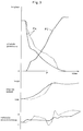
- the engagement pressure P4 of the fourth speed clutch serving as the hydraulic engagement element for the high speed stage changes as indicated by the imaginary line in the upper part of Figure 3.
- the initial decrease in the engagement pressure P4 is brought about by a narrowed passage such as a fixed orifice provided in an oil ejection passage of the fourth speed clutch, and progresses in a relatively gradual manner.
- the subsequent reduction in the engagement pressure is also carried out in a gradual manner because the ejection of the pressure of an accumulator associated with the fourth speed clutch for mitigating the shock of clutch engagement proceeds at the same time.
- the valve member which has been biased by a spring in the direction to close the oil ejection passage is displaced with the increase in the engagement pressure P2 of the second speed clutch which acts upon a land of the valve member against this spring force, the oil ejection control valve opens up (as indicated by P in the drawing).
- the engagement pressures P2 and P4 of the two clutches are supplied and ejected as described above, and the rotational speed of the engine also changes accordingly as indicated by the imaginary line in the middle part of Figure 3.
- the increase in the rotational speed of the engine is gradual in the initial part of the transmission operation, and this is due to the fact that the ejection of pressure from the fourth speed clutch occurs in a gradual manner and the engagement condition of the fourth speed stage allows torque to be transmitted to a certain extent. Thereafter, since the engagement force declines as pressure is removed from the fourth speed clutch, and the engagement pressure of the fourth speed clutch sharply declines by the opening of the oil ejection control valve, the rotational speed of the engine rises sharply.
- the acceleration of the vehicle body G also changes from a negative value to a positive value as indicated by the imaginary line in the lower part of the drawing and the resulting transmission shock is transmitted to the vehicle occupant because the decline in the engagement pressure of the fourth speed clutch and the rise in the engagement pressure of the second speed clutch are both sharp or abrupt.
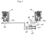
- FIG. 7 shows an exemplary oil ejection control valve 49' which is employed at the time of upshifting from a second speed stage to a third speed stage.
- This upshift operation is carried out by supplying oil pressure from a conduit 59 to a third speed clutch 17 via a port 17a leading to an oil chamber of this clutch, and ejecting oil from an oil chamber of a second speed clutch 16 via a port 16a.
- the port 16a communicates with a fixed orifice 60 via a conduit 52 when a 2-3 shift valve 58 is opened as a result of the upshift operation.
- the oil ejection control valve 49' is provided with a spool valve member 50' which is normally biased by a spring 57' to a position to close the communication between an inlet port 55' connected to the conduit 52 and an outlet port 56' connected to a pressure sink or an oil reservoir.
- the pressure supplied to the conduit 59 acts upon the spool valve member 50' and urges it to a position to establish a communication between the inlet port 55' and the outlet port 56'.
- the disengagement of the second speed clutch 16 is initially gradual, and is then accelerated in a later stage of the upshift operation so that a substantially transmission shock was inevitable.
- the oil ejection control valve is so designed to minimize the transmission shock under a relatively heavy load condition as is usually the case, a significant transmission shock occurs when an upshift operation is made under a light load condition.
- a primary object of the present invention is to provide an improved hydraulic control device for an automatic automotive transmission system which can reduce the transmission shock in all conditions.
- a second object of the present invention is to provide an improved hydraulic control device for an automatic automotive transmission system which can reduce the transmission shock in the downshift operation with the accelerator pedal depressed.
- a third object of the present invention is to provide an improved hydraulic control device for an automatic automotive transmission system which can reduce the transmission shock in the upshift operation under a light load condition such as an engine brake situation produced by the release of the accelerator pedal.
- a fourth object of the present invention is to provide an improved hydraulic control device for an automatic automotive transmission system which can reduce undesirable impulsive striking of gear teeth of two gears which are caused to mesh with each other during a transmission operation.
- a hydraulic control device for an automatic automotive transmission system in which a speed stage is selected from a plurality of speed stages by ejecting pressure from a first hydraulic engagement element provided in a path of power transmission and supplying pressure to a second hydraulic engagement element provided in another path of power transmission, comprising: an oil ejection passage connected to a port of an oil chamber of the first hydraulic engagement element; an oil ejection control valve having an inlet port connected to the oil ejection passage, an outlet port connected to an oil reservoir, a valve member, spring means urging the valve member to a position to substantially close a communication between the inlet port and the outlet port, a first pressure input port for applying pressure to a first pressure receiving surface of the valve member to move the valve member in a direction to open a communication between the inlet port and the outlet port against a biasing force of the spring means, and a second pressure input port for applying pressure to a second pressure receiving surface of the valve member to move the valve member in a direction to open a
- the valve member of the oil ejection control valve for adjusting the flow resistance of the oil ejection passage of the hydraulic engagement element for the high speed stage is controlled by both the pressure ejected from the hydraulic engagement element for the high speed stage and the pressure supplied to the hydraulic engagement element for the low speed stage during the downshift operation with the accelerator pedal depressed, the valve member can be moved with the high ejection pressure from the hydraulic engagement element for the high speed stage in an initial part of the transmission operation, and with the rising pressure supplied to the hydraulic engagement element for the low speed stage in a later part of the transmission operation to make up for the reduction in the pressure ejected from the hydraulic engagement element for the high speed stage. Therefore, it is possible to promptly reduce pressure from the hydraulic engagement element for the high speed stage in an initial part of the transmission operation, and the subsequent reduction of the engagement pressure can be carried out without involving any abruptness.
- the present invention when the present invention is applied to the case of an upshift operation, since the movement of the valve member of the oil ejection control valve for adjusting the flow resistance of the oil ejection passage of the hydraulic engagement element for the low speed stage is controlled by both the pressure supplied to the hydraulic engagement element for the high speed stage and the pressure ejected from the hydraulic engagement element for the low speed stage during the upshift operation from the low speed stage to the high speed stage, the oil pressure for the low speed stage is reduced in proportion to the increase in the engagement pressure for the high speed stage, and the opening movement of the valve member can be controlled by a relatively smoothly changing force which combines the contributions from these two pressures.
- an automatic transmission system 2 is attached to an internal combustion engine 1, and this automatic transmission system 2 comprises a torque converter 3 having a lock-up clutch and a gear transmission unit 4 with four forward speed stages and one reverse speed stage equipped with a hold clutch.
- a ring gear of a differential gear unit 6 coupled to driven wheels 5 meshes with a final drive gear 4a of the gear transmission unit 4 so that the output torque of the engine 1 may be transmitted to the driven wheels 5 via the torque converter 3 and the gear transmission unit 4.
- the speed stages of the automatic transmission system 2 are controlled by a control unit 7 serving as a means for controlling the automatic transmission operation according to a vehicle speed signal and a throttle opening signal representing the load condition of the engine.
- the control unit 7 operates electronically, and comprises a CPU, ROM, RAM and input and output interface circuits 7a and 7b.
- the input interface circuit 7a receives a pulse signal from a vehicle speed sensor 8 associated with the final drive gear 4a as a vehicle speed signal, and a voltage signal from a throttle opening sensor 9 mounted on a throttle body not shown in the drawing as a throttle opening signal.
- the input interface circuit 7a may further receive signals from other sensors 10 which, for instance, detect the condition of an air conditioner, and the temperature of the engine cooling water.
- the CPU of the control unit 7 carries out a map control for the operation of the automatic transmission system 2 by using the CPU, the ROM and the RAM according to the signals supplied to the input interface circuit 7a.
- the output interface circuit 7b of the control unit 7 supplies a shift control signal and a lock-up control signal to various solenoid valves SV for shift control and lock-up control of an hydraulic control circuit 11 of the automatic transmission system 2.
- the hydraulic control circuit 11 automatically shifts the gears of the gear transmission unit 4 of the automatic transmission system 2 as required.
- This gear transmission unit 4 consists of, for instance, a constant-mesh type transmission gear unit having an input shaft 12, an output shaft 13 and a counter shaft 14 disposed in a mutually parallel relationship.
- the counter shaft 14 which is engaged with the input shaft 12 by means of gears including idle gears is provided with a first speed clutch 15 for establishing the first speed stage, and a second speed clutch 16 for establishing the second speed stage, and the input shaft 12 is provided with a third speed clutch 17 for establishing the third speed stage, and a fourth speed clutch 18 for establishing the fourth speed stage.
- the output shaft 13 is provided with a one-way clutch 19 coupled to a first speed gear for permitting the overrunning of the output shaft 13, and the transmission of torque via the first speed gear is avoided.
- a hold clutch LH is provided in parallel with the one-way clutch 19 so that torque may be transmitted by the hold clutch LH by overriding the one-way clutch 19 when the hold clutch LH is engaged.
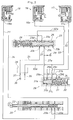
- Figure 2 is a schematic hydraulic circuit diagram of an essential part of the hydraulic control circuit 11 to which the present invention is applied.
- a port 18a leading to an oil chamber of the fourth speed clutch 18 is communicated with a first port 20a of a manual valve 20 via a first oil passage 21.
- This manual valve 20 has a spool valve member 22 which can move laterally as seen in the drawing, and, in this illustrated condition in which a D range is selected, any one of the first through the fourth speed stages may be automatically established by suitable shifting operations.
- a second port 20b of the manual valve 20 communicating with the first port 20a via an annular groove formed in the spool valve member 22 is communicated with a first port 23a of a 3-4 shift valve 23 via a second oil passage 24.
- a spool valve member 25 of this 3-4 shift valve 23 is elastically biased to the right in the drawing by a spring 26.
- a low speed stage or the second speed stage is achieved after the vehicle has been travelling in a high speed stage or the fourth speed stage, and, when the second speed stage is achieved, an oil chamber remote from the spring 26 does not receive any oil pressure from a control valve not shown in the drawing via a second port 23b, and the spool valve member 25 is elastically biased to the right under the biasing force of the spring 26 as shown in the drawing.
- the 3-4 shift valve 23 is provided with a third port 23c which communicates with the first port 23a via an outer circumferential groove formed in the spool valve member 25 when the second speed stage is achieved, and the third port 23c is connected to a first oil ejection passage 27 which communicates with the atmosphere via a fixed orifice 28.
- a branch passage 27a branching out from an intermediate part of the first oil ejection passage 27 upstream of the fixed orifice 28 is connected to a first input port 29a of an oil ejection control valve 29.
- the ejection oil pressure supplied to the first input port 29a is applied to a first annular land 31a of a spool valve member 31 of the oil ejection control valve 29 so that the spool valve member 31 which is biased to the left in the drawing by a spring 30 may be displaced to the right against the spring biasing force by the ejection pressure supplied to the first input port 29a.
- the oil ejection control valve 29 is provided with second through fourth input ports 29b through 29d, and the second input port 29b is connected to a port 17a leading to an oil chamber of the third speed clutch 17, via a third oil passage 32, while the third input port 29c is connected to a port 16a leading to an oil chamber of the second speed clutch 16, via a fourth oil passage 33, in such a manner that the ejection pressures may be applied to second and third annular lands 31b and 31c of the spool valve member 31, and the ejection pressures selectively supplied to the two ports 29b and 29c may displace the spool valve member 31 against the spring biasing force.
- a secondary branch passage 27b branching further out from the branch passage 27a is connected to the fourth input port 29d of the oil ejection control valve 29, and the oil ejection control valve 29 is provided with an oil ejection port 34 which communicates with the fourth input port 29d via an outer circumferential groove of the spool valve member 31 when the spool valve member 31 is displaced to the right in the drawing against the spring biasing force.
- a fourth port 23d of the 3-4 shift valve 23 is connected to a branch passage 32a which branches out from a third oil passage 32 connected to the port 17a of the third speed clutch 17.
- the 3-4 shift valve 23 is provided with a fifth port 23e which communicates with the fourth port 23d via an outer circumferential groove of the spool valve member 31 when the spool valve member 31 is in the illustrated position, and a fifth oil passage 35 connected to this fifth port 23e is selectively communicated with a second oil ejection passage 37 communicating with the atmosphere via a fixed orifice 36.
- a branch passage 33a branching out from the fourth oil passage 33a is selectively connected to an oil supply passage 39 connected to an oil supply pump not shown in the drawing by way of a 2-3 shift valve 38.
- the engagement pressure in the oil chamber of the fourth speed clutch 18 is removed, and the clutch is disengaged from its engaged condition.
- the removal of the engagement pressure is made via the first oil ejection passage 27 according to the condition of communication between the first and the third ports 23a and 23c of the 3-4 shift valve 23.
- the engagement pressure is removed via the fixed orifice 28 alone, and, since the ejection oil pressure is applied to the first land 31a via the first input port 29a of the oil ejection control valve 29 and the branch passage 27a, the spool valve member 31 is displaced to the right in the drawing against the elastic biasing force of the spring 30.
- the decrease in the pressure of the fourth speed clutch 18 takes place in association with the increase in the pressure of the second speed clutch 16 according to the ratio between the areas Sa and Sb of the first land 29a and the second land 29b, and the drive force F can be kept substantially constant by suitably determining the area ratio.
- the oil ejection control valve 29 opens up more speedily by the ejection pressure from the fourth speed clutch 18, and, even when the ejection pressure has declined, the opening of the valve is maintained by the rise in the engagement pressure of the third speed clutch 17 so that a smooth transmission operation is ensured in a similar manner as in the previously described embodiment.
- the removal of pressure from the hydraulic engagement element for the high speed stage is carried out while controlling the opening operation of the oil ejection control valve with a relatively smoothly changing drive force for moving the valve member in the direction to open the valve by combining the rise and fall of the supply pressure to the hydraulic engagement element for the low speed stage and the ejection pressure from the hydraulic engagement element for the low speed stage during a transmission operation from the high speed stage to the low speed stage, the change in the ejection pressure can be mitigated, and the quality of the transmission operation can be improved by reducing the transmission shock during a downshift operation such as a kick-down operation.
- the port 16a of the oil chamber of the second speed clutch 16 is communicated with a first input port 51 of an oil ejection control valve 49 via a first oil passage 52, and a second input port 53 of the oil ejection control valve 49 is communicated with the port 17a of an oil chamber of the third speed clutch 17 via a second oil passage 54.
- the first oil passage 52 is also communicated with a third input port 55 of the oil ejection control valve 49.
- This oil ejection control valve 49 is provided with a spool valve member 50 which can move back and forth so as to selectively communicate the input port 55 to an oil ejection port 56 of the oil ejection control valve 49, and is elastically urged by a spring 57 in the direction to close the oil ejection port 56.
- the valve member 50 is provided with a first annular pressure receiving surface 50a to which the oil pressure supplied to the first input port 51 is applied, and a second annular pressure receiving surface 50a to which the pressure supplied to the second input port 53 is applied.
- first annular pressure receiving surface 50a to which the oil pressure supplied to the first input port 51 is applied
- second annular pressure receiving surface 50a to which the pressure supplied to the second input port 53 is applied.
- the first oil passage 52 is provided with a 2-3 shift valve 58 in an intermediate part thereof, and the activation of the 2-3 shift valve 58 causes the port 16a of the second speed clutch 16 to be communicated with the first and third input ports 51 and 55 of the oil ejection control valve 49.
- a branch passage 59 provided in an intermediate part of the second oil passage 54 is provided with a 3-4 shift valve not shown in the drawing, and the activation of this 3-4 shift valve causes oil pressure to be supplied to and ejected from the oil chamber of the third speed clutch 17 in a similar manner as described above.
- the third input port 55 communicates with the oil ejection port 56.
- the engagement pressure of the clutch 17 for the higher speed stage or the third speed stage is low, and the displacement of the valve member 50 is caused primarily by the high ejection oil pressure from the clutch 16 for the lower speed stage or the second speed stage so as to rapidly reduce the engagement oil pressure of the second speed clutch 16.
- the engagement oil pressure of the second speed clutch 16 is reduced more gradually than the prior art which is indicated in the imaginary line in the upper part of Figure 5 according to the rise in the engagement oil pressure of the third speed clutch 17 and the ratio of the areas of the pressure receiving surfaces 50a and 50b.
- the engagement force of the second speed clutch 16 is reduced with the result that the change-over in the role of torque transmission between the two clutches takes place in a smooth manner without any sudden change in the transmitted torque, and the transmission shock can be substantially reduced.
- a particularly significant reduction in the transmission torque can be effected.
- the driven gear for the third speed stage is freely rotating if the drive gear for the third speed stage is fixed to the input shaft 12 or the drive gear for the third speed stage is freely rotating if the driven gear for the third speed stage is fixed to the output shaft 13.
- the engagement force of the second speed clutch 16 is abruptly lost, the play in the meshing engagement of the gears in the third speed stage causes an impulsive sound.
- the slip ratio of the third speed clutch 17 rapidly changes as indicated by the imaginary line in the lower part of Figure 5, and a substantial impulsive sound is produced.
- the second speed clutch 16 since the second speed clutch 16 is disengaged with the engagement pressure thereof removed via the oil ejection port 56 of the oil ejection control valve 49 in a controlled fashion, the pressure is gradually removed as indicated by the oil ejection line A, and the change in the slip ratio likewise takes place in a gradual manner as indicated by the solid line so that the relative movement of the teeth of the two gears for the third speed stage is subjected to a braking action due to the engagement pressure of the second speed clutch 16 remaining until the completion of the upshift transmission operation, and a favorable transmission operation can be accomplished without involving undesirable impulsive noises.
- FIG. 6 is a view similar to Figure 4 showing yet another embodiment of the present invention, and like parts are denoted with like numerals without repeating description of such parts.
- the oil ejection control valve 61 for controlling the removal of oil pressure in this embodiment is provided with an ejection oil inlet port 71 connected to the first oil passage 52, and first and second ports 64 and 65 for moving a valve member 62 against the elastic biasing force of a spring 63.
- the first port 64 is connected, via a third oil passage 73, to an output port 67 of a switch valve 66 which switches over according to the throttle opening of the throttle valve determined by the amount of accelerator pedal depression relative to a prescribed value, and the second port 65 is connected to the port 17a of the third speed clutch 17 via the second oil passage 54.
- the switch valve 66 is provided with a supply pressure input port 74 and an ejection pressure input port 75.
- the supply pressure input port 74 is connected to a branch passage 54a branching out from the second oil passage 54, and the ejection pressure input port 75 is connected to a branch passage 52a of the first oil passage 52.
- valve member 62 of the oil ejection control valve 61 when the valve member 62 of the oil ejection control valve 61 is biased by the spring 63, the ejection oil inlet port 71 connected to the port 16a of the second speed clutch 16 is shut off from an oil ejection port 72.
- the valve member 62 is provided with first and second pressure receiving surfaces 62a and 62b in a similar manner as in the previous embodiment, and, when the valve member 62 is moved to the right in the drawing against the elastic biasing force by the pressures applied to the pressure receiving surfaces, the ejection oil inlet port 71 is communicated with the ejection oil port 72.
- the switch valve 66 consisted of a hydraulic valve which switches over according to the throttle pressure determined by the throttle opening of the throttle valve, but may also be a solenoid valve which switches over according to an electric signal related to the throttle opening.
- an upshift transmission operation from the low speed stage to the high speed stage is made by controlling the movement of a valve member of an ejection oil control valve in the direction to open an oil ejection passage with a valve member driving force which changes relatively smoothly by combining the rise and fall of the supply pressure to a hydraulic engagement element for the high speed stage and the ejection pressure from a hydraulic engagement element for the low speed stage, the change in the ejection oil pressure can be mitigated, and the transmission shock at the time of an upshift transmission operation under a light engine load condition can be reduced.
Landscapes
- Engineering & Computer Science (AREA)
- General Engineering & Computer Science (AREA)
- Physics & Mathematics (AREA)
- Fluid Mechanics (AREA)
- Mechanical Engineering (AREA)
- Control Of Transmission Device (AREA)
Applications Claiming Priority (4)
| Application Number | Priority Date | Filing Date | Title |
|---|---|---|---|
| JP275753/90 | 1990-10-15 | ||
| JP2275753A JP2781065B2 (ja) | 1990-10-15 | 1990-10-15 | 車両用自動変速機の油圧制御装置 |
| JP1398291A JP2912033B2 (ja) | 1991-01-11 | 1991-01-11 | 車両用自動変速機の油圧制御装置 |
| JP13982/91 | 1991-01-11 |
Publications (3)
| Publication Number | Publication Date |
|---|---|
| EP0481393A2 true EP0481393A2 (fr) | 1992-04-22 |
| EP0481393A3 EP0481393A3 (en) | 1993-10-20 |
| EP0481393B1 EP0481393B1 (fr) | 1998-02-11 |
Family
ID=26349845
Family Applications (1)
| Application Number | Title | Priority Date | Filing Date |
|---|---|---|---|
| EP91117467A Expired - Lifetime EP0481393B1 (fr) | 1990-10-15 | 1991-10-14 | Système de commande hydraulique pour une transmission automatique de véhicule |
Country Status (3)
| Country | Link |
|---|---|
| US (1) | US5154099A (fr) |
| EP (1) | EP0481393B1 (fr) |
| DE (1) | DE69128907T2 (fr) |
Cited By (1)
| Publication number | Priority date | Publication date | Assignee | Title |
|---|---|---|---|---|
| EP0583954A1 (fr) * | 1992-08-14 | 1994-02-23 | Mitsubishi Jidosha Kogyo Kabushiki Kaisha | Dispositif et méthode pour le réglage du changement de vitesse sur une transmission automatique de véhicule |
Families Citing this family (8)
| Publication number | Priority date | Publication date | Assignee | Title |
|---|---|---|---|---|
| JP2881175B2 (ja) * | 1991-12-03 | 1999-04-12 | アイシン・エィ・ダブリュ株式会社 | 自動変速機のサーボ油圧制御装置 |
| KR960000631B1 (ko) * | 1991-12-30 | 1996-01-10 | 현대자동차주식회사 | 자동 변속기 유압제어장치의 방향절환밸브 |
| US5551930A (en) * | 1995-04-13 | 1996-09-03 | Caterpillar Inc. | Adaptive control method for an automatic transmission |
| US5580332A (en) * | 1995-04-13 | 1996-12-03 | Caterpillar Inc. | Method for determining the fill time of a transmission clutch |
| US6115661A (en) * | 1998-04-09 | 2000-09-05 | Caterpillar Inc. | End-of-fill detector for a fluid actuated clutch |
| US5950789A (en) * | 1998-04-27 | 1999-09-14 | Caterpillar Inc. | End of fill detector for a fluid actuated clutch |
| JP3838422B2 (ja) * | 2000-12-06 | 2006-10-25 | 現代自動車株式会社 | 車両用自動変速機の変速制御装置およびその方法 |
| US7933708B2 (en) * | 2007-08-10 | 2011-04-26 | Toyota Motor Engineering & Manufacturing North America, Inc. | Systems and methods for assisting in acceleration of a vehicle during vehicle re-acceleration |
Family Cites Families (17)
| Publication number | Priority date | Publication date | Assignee | Title |
|---|---|---|---|---|
| JPS4820655B1 (fr) * | 1970-02-12 | 1973-06-22 | ||
| JPS4838579B1 (fr) * | 1970-12-18 | 1973-11-19 | ||
| JPS4940585A (fr) * | 1972-08-18 | 1974-04-16 | ||
| US4265346A (en) * | 1979-01-04 | 1981-05-05 | Ford Motor Company | Control valve mechanism for hydraulic clutch in a power transmission mechanism |
| JPH0625594B2 (ja) * | 1982-08-20 | 1994-04-06 | 日産自動車株式会社 | 自動変速機の油圧制御装置 |
| JPS6182054A (ja) * | 1984-09-28 | 1986-04-25 | Aisin Warner Ltd | 自動変速機の油圧制御装置 |
| JPS6184450A (ja) * | 1984-10-02 | 1986-04-30 | Honda Motor Co Ltd | 車両用油圧作動式変速機の制御装置 |
| JP2543527B2 (ja) * | 1987-06-15 | 1996-10-16 | 日産自動車株式会社 | 自動変速機のシフトバルブ |
| JPH0820008B2 (ja) * | 1987-10-30 | 1996-03-04 | 日産自動車株式会社 | 自動変速機のライン圧制御装置 |
| JPH0820013B2 (ja) * | 1987-10-30 | 1996-03-04 | 日産自動車株式会社 | 自動変速機の変速制御装置 |
| JPH0231073A (ja) * | 1988-07-19 | 1990-02-01 | Aisin Aw Co Ltd | 自動変速機における油圧制御装置 |
| US4858501A (en) * | 1988-08-11 | 1989-08-22 | General Motors Corporation | Shift inhibit valve for a transmission control |
| JP2605840B2 (ja) * | 1988-11-16 | 1997-04-30 | 日産自動車株式会社 | 無段変速機の変速制御装置 |
| JPH02134456A (ja) * | 1988-11-16 | 1990-05-23 | Honda Motor Co Ltd | 車両用油圧作動式変速機の制御装置 |
| JP2813681B2 (ja) * | 1989-03-31 | 1998-10-22 | アイシン精機株式会社 | 自動変速機の油圧制御装置 |
| JP2830174B2 (ja) * | 1989-09-30 | 1998-12-02 | アイシン精機株式会社 | 自動変速機の変速制御装置 |
| JPH06184450A (ja) * | 1992-12-16 | 1994-07-05 | Ricoh Co Ltd | 新規なアゾ化合物、ジアゾニウム塩およびそれらの製造方法 |
-
1991
- 1991-10-11 US US07/774,093 patent/US5154099A/en not_active Expired - Lifetime
- 1991-10-14 EP EP91117467A patent/EP0481393B1/fr not_active Expired - Lifetime
- 1991-10-14 DE DE69128907T patent/DE69128907T2/de not_active Expired - Lifetime
Cited By (2)
| Publication number | Priority date | Publication date | Assignee | Title |
|---|---|---|---|---|
| EP0583954A1 (fr) * | 1992-08-14 | 1994-02-23 | Mitsubishi Jidosha Kogyo Kabushiki Kaisha | Dispositif et méthode pour le réglage du changement de vitesse sur une transmission automatique de véhicule |
| US5445579A (en) * | 1992-08-14 | 1995-08-29 | Mitsubishi Jidosha Kogyo Kabushiki Kaisha | Speed change control apparatus and method for an automatic transmission in a vehicle |
Also Published As
| Publication number | Publication date |
|---|---|
| EP0481393B1 (fr) | 1998-02-11 |
| DE69128907T2 (de) | 1998-05-28 |
| US5154099A (en) | 1992-10-13 |
| EP0481393A3 (en) | 1993-10-20 |
| DE69128907D1 (de) | 1998-03-19 |
Similar Documents
| Publication | Publication Date | Title |
|---|---|---|
| US4513639A (en) | Creeping preventing apparatus in automatic transmission for vehicle | |
| US4516671A (en) | Control apparatus for a torque convertor clutch | |
| US4485695A (en) | Control apparatus for automatic transmissions | |
| EP0213852B1 (fr) | Commande de la pression d'huile d'une transmission variable d'une manière continue | |
| US4561328A (en) | Creeping preventing apparatus in automatic transmission for vehicle | |
| CA1121182A (fr) | Systeme hydraulique de commande pour train d'engrenages planetaires, particulierement pour vehicules automobiles | |
| EP0297727A2 (fr) | Système à commande d'une transmission à variation de vitesses infinies avec un convertisseur de couple | |
| EP0640780B1 (fr) | Système de commande à changement de vitesses pour une transmission automatique | |
| US4909103A (en) | System for controlling a continuously variable transmission having a torque converter | |
| US5211082A (en) | Control apparatus for automatic transmission | |
| EP0118003A2 (fr) | Dispositif de commande d'une transmission avec suppression du choc de changement de vitesse | |
| US5154099A (en) | Hydraulic control device for an automatic automotive transmission system | |
| US4573375A (en) | Control system and method for automatic transmission for automotive vehicle | |
| JPS6346302B2 (fr) | ||
| JPH0121379B2 (fr) | ||
| JPS6346303B2 (fr) | ||
| JPS628662B2 (fr) | ||
| US5010788A (en) | Automatic automotive transmission having 4-2 downshift sequence valve | |
| JPH08121592A (ja) | 自動変速機のロックアップ制御装置 | |
| GB1191388A (en) | Automatic Control Valve System for a Multiple Ratio Power Transmission Mechanism. | |
| US5095775A (en) | Hydraulic pressure control system for automatic transmission | |
| JP2979448B2 (ja) | 車両用自動変速機の制御装置 | |
| JPH07113408B2 (ja) | 自動変速機の液圧制御装置 | |
| JPS61278651A (ja) | 車輌用自動変速機のアイドル運転時制御方法 | |
| JP2798252B2 (ja) | 自動変速機におけるシフト制御装置 |
Legal Events
| Date | Code | Title | Description |
|---|---|---|---|
| PUAI | Public reference made under article 153(3) epc to a published international application that has entered the european phase |
Free format text: ORIGINAL CODE: 0009012 |
|
| AK | Designated contracting states |
Kind code of ref document: A2 Designated state(s): DE FR GB |
|
| PUAL | Search report despatched |
Free format text: ORIGINAL CODE: 0009013 |
|
| AK | Designated contracting states |
Kind code of ref document: A3 Designated state(s): DE FR GB |
|
| 17P | Request for examination filed |
Effective date: 19940315 |
|
| 17Q | First examination report despatched |
Effective date: 19951129 |
|
| GRAG | Despatch of communication of intention to grant |
Free format text: ORIGINAL CODE: EPIDOS AGRA |
|
| GRAG | Despatch of communication of intention to grant |
Free format text: ORIGINAL CODE: EPIDOS AGRA |
|
| GRAH | Despatch of communication of intention to grant a patent |
Free format text: ORIGINAL CODE: EPIDOS IGRA |
|
| GRAH | Despatch of communication of intention to grant a patent |
Free format text: ORIGINAL CODE: EPIDOS IGRA |
|
| GRAA | (expected) grant |
Free format text: ORIGINAL CODE: 0009210 |
|
| AK | Designated contracting states |
Kind code of ref document: B1 Designated state(s): DE FR GB |
|
| REF | Corresponds to: |
Ref document number: 69128907 Country of ref document: DE Date of ref document: 19980319 |
|
| ET | Fr: translation filed | ||
| PLBE | No opposition filed within time limit |
Free format text: ORIGINAL CODE: 0009261 |
|
| STAA | Information on the status of an ep patent application or granted ep patent |
Free format text: STATUS: NO OPPOSITION FILED WITHIN TIME LIMIT |
|
| 26N | No opposition filed | ||
| REG | Reference to a national code |
Ref country code: GB Ref legal event code: IF02 |
|
| PGFP | Annual fee paid to national office [announced via postgrant information from national office to epo] |
Ref country code: FR Payment date: 20031003 Year of fee payment: 13 |
|
| PG25 | Lapsed in a contracting state [announced via postgrant information from national office to epo] |
Ref country code: FR Free format text: LAPSE BECAUSE OF NON-PAYMENT OF DUE FEES Effective date: 20050630 |
|
| REG | Reference to a national code |
Ref country code: FR Ref legal event code: ST |
|
| PGFP | Annual fee paid to national office [announced via postgrant information from national office to epo] |
Ref country code: GB Payment date: 20061011 Year of fee payment: 16 |
|
| GBPC | Gb: european patent ceased through non-payment of renewal fee |
Effective date: 20071014 |
|
| PG25 | Lapsed in a contracting state [announced via postgrant information from national office to epo] |
Ref country code: GB Free format text: LAPSE BECAUSE OF NON-PAYMENT OF DUE FEES Effective date: 20071014 |
|
| PGFP | Annual fee paid to national office [announced via postgrant information from national office to epo] |
Ref country code: DE Payment date: 20101006 Year of fee payment: 20 |
|
| REG | Reference to a national code |
Ref country code: DE Ref legal event code: R071 Ref document number: 69128907 Country of ref document: DE |
|
| REG | Reference to a national code |
Ref country code: DE Ref legal event code: R071 Ref document number: 69128907 Country of ref document: DE |
|
| PG25 | Lapsed in a contracting state [announced via postgrant information from national office to epo] |
Ref country code: DE Free format text: LAPSE BECAUSE OF EXPIRATION OF PROTECTION Effective date: 20111015 |