EP0481423B1 - Assemblage d'une pompe électrique - Google Patents
Assemblage d'une pompe électrique Download PDFInfo
- Publication number
- EP0481423B1 EP0481423B1 EP91117572A EP91117572A EP0481423B1 EP 0481423 B1 EP0481423 B1 EP 0481423B1 EP 91117572 A EP91117572 A EP 91117572A EP 91117572 A EP91117572 A EP 91117572A EP 0481423 B1 EP0481423 B1 EP 0481423B1
- Authority
- EP
- European Patent Office
- Prior art keywords
- rotor
- pump
- rotation
- pump assembly
- cup
- Prior art date
- Legal status (The legal status is an assumption and is not a legal conclusion. Google has not performed a legal analysis and makes no representation as to the accuracy of the status listed.)
- Expired - Lifetime
Links
- 238000004804 winding Methods 0.000 claims abstract description 29
- 239000012530 fluid Substances 0.000 claims abstract description 10
- 230000005355 Hall effect Effects 0.000 claims description 4
- 230000006378 damage Effects 0.000 claims description 3
- 238000010276 construction Methods 0.000 description 3
- 230000007423 decrease Effects 0.000 description 2
- 230000003247 decreasing effect Effects 0.000 description 2
- 230000005284 excitation Effects 0.000 description 2
- 229920013632 Ryton Polymers 0.000 description 1
- 239000004736 Ryton® Substances 0.000 description 1
- 239000004809 Teflon Substances 0.000 description 1
- 229920006362 Teflon® Polymers 0.000 description 1
- 230000000712 assembly Effects 0.000 description 1
- 238000000429 assembly Methods 0.000 description 1
- 239000000919 ceramic Substances 0.000 description 1
- 239000002131 composite material Substances 0.000 description 1
- 238000011109 contamination Methods 0.000 description 1
- 238000010586 diagram Methods 0.000 description 1
- 239000000463 material Substances 0.000 description 1
- AJCDFVKYMIUXCR-UHFFFAOYSA-N oxobarium;oxo(oxoferriooxy)iron Chemical compound [Ba]=O.O=[Fe]O[Fe]=O.O=[Fe]O[Fe]=O.O=[Fe]O[Fe]=O.O=[Fe]O[Fe]=O.O=[Fe]O[Fe]=O.O=[Fe]O[Fe]=O AJCDFVKYMIUXCR-UHFFFAOYSA-N 0.000 description 1
- 230000035939 shock Effects 0.000 description 1
- 229910001220 stainless steel Inorganic materials 0.000 description 1
- 239000010935 stainless steel Substances 0.000 description 1
- 230000003685 thermal hair damage Effects 0.000 description 1
Images


Classifications
-
- H—ELECTRICITY
- H02—GENERATION; CONVERSION OR DISTRIBUTION OF ELECTRIC POWER
- H02K—DYNAMO-ELECTRIC MACHINES
- H02K29/00—Motors or generators having non-mechanical commutating devices, e.g. discharge tubes or semiconductor devices
- H02K29/06—Motors or generators having non-mechanical commutating devices, e.g. discharge tubes or semiconductor devices with position sensing devices
- H02K29/08—Motors or generators having non-mechanical commutating devices, e.g. discharge tubes or semiconductor devices with position sensing devices using magnetic effect devices, e.g. Hall-plates, magneto-resistors
-
- F—MECHANICAL ENGINEERING; LIGHTING; HEATING; WEAPONS; BLASTING
- F04—POSITIVE - DISPLACEMENT MACHINES FOR LIQUIDS; PUMPS FOR LIQUIDS OR ELASTIC FLUIDS
- F04C—ROTARY-PISTON, OR OSCILLATING-PISTON, POSITIVE-DISPLACEMENT MACHINES FOR LIQUIDS; ROTARY-PISTON, OR OSCILLATING-PISTON, POSITIVE-DISPLACEMENT PUMPS
- F04C15/00—Component parts, details or accessories of machines, pumps or pumping installations, not provided for in groups F04C2/00 - F04C14/00
- F04C15/0057—Driving elements, brakes, couplings, transmission specially adapted for machines or pumps
- F04C15/008—Prime movers
-
- H—ELECTRICITY
- H02—GENERATION; CONVERSION OR DISTRIBUTION OF ELECTRIC POWER
- H02K—DYNAMO-ELECTRIC MACHINES
- H02K5/00—Casings; Enclosures; Supports
- H02K5/04—Casings or enclosures characterised by the shape, form or construction thereof
- H02K5/12—Casings or enclosures characterised by the shape, form or construction thereof specially adapted for operating in liquid or gas
- H02K5/128—Casings or enclosures characterised by the shape, form or construction thereof specially adapted for operating in liquid or gas using air-gap sleeves or air-gap discs
Definitions
- the present invention relates to a pump assembly, and more particularly relates to a pump assembly in which the torque used to power the pump is transmitted magnetically across a statically sealed interface.
- Gear pumps are conventionally housed in sealed enclosures from which the pump drive shaft extends. A drive motor is then coupled to the shaft to drive the pump head.
- US-A-3 238 883 and US-A-4 111 614 teach the use of a magnet drive system wherein a drive shaft needn't extend through the pump housing.
- the drive shaft 10 has mounted thereon a magnet 12 that is enclosed within a fluid-tight cylindrical extension 14 of the pump housing 16. Outside this portion of the housing is disposed a cylindrical driving magnet 18 that is magnetically coupled to the magnet inside the housing. By rotating the external cylindrical magnet 18, the magnet 12 on the drive shaft inside the housing, and thus the drive shaft 10, are caused to rotate.
- a second problem common to both direct and magnet drive systems is the use of brushed motors.
- electrically conductive "brushes” are spring biased against the rotor shaft to make electrical connections with windings mounted thereon. Due to their reliance on an electromechanical contact against a moving element, motor brushes are prone to intermittent contacts and ultimately failure.
- a third problem common to both the direct and magnet drive systems is the space that the motor requires. Pump assemblies are often the largest components in the apparatuses in which they are used. Of this size, the pump drive motor generally contributes more than half. If the size of the composite pump head/motor/controller assembly could be reduced, significant economies of space, and consequently of money, could be achieved in the apparatuses in which pumps are employed.
- DE-A-38 22 897 discloses a pump assembly provided with a magnet drive system.
- the rotor of the drive system is mounted on a stationary shaft which extends through the rotor and upon which is also rotatably mounted a pump head.
- Two bearings, one at either end of the stationary shaft, are provided.
- the pre-characterising features of Claim 1 are based upon the disclosure of DE-A-38 22 897.
- the foregoing need is fulfilled by integrally incorporating a motor as part of the pump assembly.
- the motor shaft bearings and seals can be eliminated, and a compact pump assembly can be provided.
- the present invention provides a pump assembly having a pump and a drive motor integrally associated therewith, the assembly including: a pump head; a permanent magnet rotor having an axis of rotation and first and second ends, the rotor being coupled to a drive component of the pump head and providing rotary motion thereto, the pump head being connected to the first end of the rotor for rotation about the axis of rotation, the second end of the rotor defining an axial bore extending at least partially through the rotor; a fluid-tight cup: having a cylindrical side wall and a closed end, the cup defining an enclosure having an open first end and a closed second end, said cup enclosure defining a cavity within which the rotor is disposed, said cavity being in fluid connection with the pump head through its open first end; a plurality of electrical stator windings disposed about the outside of the cup enclosure, adjacent thereto; a housing within which the cup enclosure and the stator windings are disposed, the fluid-tight cup having a uniform wall thickness
- a pump in more detail, includes a rotary drive shaft which, at one end, is connected to the pump head and, at the other end, is connected to a permanent magnet rotor.
- This shaft and rotor are enclosed in a cavity defined by a fluid-tight cup that has an open first end and a closed second end.
- the cavity in which the rotor rotates is in fluid connection with the pump head through its open first end.
- Outside the cup enclosure are disposed a plurality of electrical stator windings.
- a housing encloses all of the foregoing elements and may further enclose a circuit board that includes controller/driver circuitry for controlling operation of the motor and driving the stator windings.
- the circuit board also desirably includes circuitry for sensing the speed at which the motor is operating, and for adjusting the drive currents applied to the stator windings in response thereto. This feedback provides a "stiff" motor, highly immune to changing load conditions.
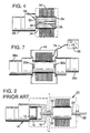
- Figure 1 is a fragmentary isometric view of a prior art magnet drive system for a gear pump or the like.
- Figure 2 is a side view of the prior art gear pump and drive system of Figure 1.
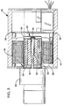
- Figure 3 is a sectional view of a drive system according to one embodiment of the present invention.
- Figure 4 is a simplified sectional view of a drive system according to a second embodiment of the present invention.
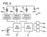
- Figure 5 is a schematic diagram of circuitry used to control the drive system of Figure 3.
- Figure 6 is a family of curves illustrating performance of a pump employing the drive system of Figure 3.
- Figure 7 illustrates an alternative form of the invention in which a single rotor and a single controller are used to drive a pair of pump heads.
- a pump assembly 26 includes a pump head 28, a rotary drive shaft 30, a permanent magnet rotor 32, a cup enclosure 34, a plurality of electrical stator windings 36, a control circuit board 38, and a housing 40.
- the pump head 28 is conventional and may comprise, for example, a gear pump.
- the gears 42 ( Figure 1) are caused to rotate and pump fluid from an inlet port to an outlet port.
- the permanent magnet rotor 32 is attached to the opposite end of the drive shaft 30.
- the rotor may be of the type illustrated in US-A-3 238 883 and US-A-4 111 614 and includes a plurality of permanent magnetic dipoles, such a barium ferrite magnets 44 ( Figure 1), radially spaced therearound.
- the magnet is desirably encapsulated in Ryton or Teflon (Trade Marks acknowledged) 46, and then sheathed in stainless steel 48. This jacketing arrangement not only ensures contamination-free operation, but also protects the ceramic magnet from damage caused by thermal shock.
- the rotor and stator are each about 38mm (1.5 inches) in length (this length is related to the torque that must be generated).
- the drive shaft 30 and rotor 32 are disposed within a cylindrical cavity 50 formed by the cup enclosures 34.
- This enclosure is open at a first end 52, where it adjoins the pump head 28, and is closed at its second end 54.
- the open first end provides free fluid communication between the pump head 28, the shaft 30, and the rotor 32.
- the cup enclosure 34 is otherwise fluid-tight.
- the clearance between the rotor 32 and the inside of the cup is quite small - on the order of 0.38mm (0.015 inch).
- a fixed post 56 Extending a short distance into the cavity 50 from the second end 54 of the cup enclosure 34 is a fixed post 56 oriented collinearly with the pump drive shaft 30.
- the rotor 32 has a bore 58 extending partially therethrough by which the rotor can be constrained to rotate on the post 56.
- a plurality of electrical coils 36 Disposed about the outside of the cup enclosure 34 are a plurality of electrical coils 36 that serve as stator windings. Pulses of current are controllably applied to these windings to produce a rotating magnetic field. The field, in turn, causes the permanent magnet rotor 32 to rotate within the cup enclosure 34, thereby driving the gear pump 28.
- stator windings 36 there are desirably an even number of stator windings 36, such as six. This arrangement prevents asymmetrical side loading of the rotor 32.
- the windings also preferably number more than two in order to provide unambiguous control of the rotor's direction of rotation.
- the rotor is desirably provided with a number of poles different than that of the stator.
- the rotor has four poles. This asymmetry insures that the rotor and stator poles cannot all be in alignment.
- the circuitry 60 that controls excitation of the stator windings 36 is disposed on a circuit board 38 positioned adjacent the closed, second end 54 of the cup enclosure 34. All of the foregoing components are encased in the exterior housing 40, thereby providing a compact unit - about half the size of prior art pump/motor combinations. (In other embodiments, of course, the controller/driver circuitry need not be positioned within the exterior housing but can be at a location remote from the pump head/motor assembly and connected thereto by appropriate wiring.
- the control circuitry 60 that controls excitation of the stator windings 36 is illustrated in Fig. 5 and is built around a Motorola MC33035 brushless DC motor controller integrated circuit 62 and a Motorola MC33039 tachometer integrated circuit 64.
- the speed of rotor rotation is set by a potentiometer 66 that controls the rate at which output signal pulses are applied to output terminals of the controller circuit 62. These pulses drive three drive circuits 68a, 68b, 68c that in turn apply current pulses to opposing pairs of stator windings.
- the circuitry can be configured so that it is responsive to an externally applied speed control signal.
- This control signal may take several forms, including variable amplitude voltage or current signals, pulse width modulated signals, digital control signals, etc.
- Rotation of the rotor 32 is sensed by three Hall effect sensors 70a, 70b, 70c that each produce a logic "0" output signal when a south magnetic pole passes thereby.
- the sensors 70 are connected to the circuit board 38 (Fig. 3) adjacent the second end 54 of the cup enclosure 34, thereby permitting them to sense the magnetic field of the stator windings.
- the signals from these sensors are applied to the tachometer circuit 64, which produces an output signal related to the rotor's rate of rotation. This output signal is applied to an error input of the controller circuit 62 and compared against a signal corresponding to the desired rate of rotation (set by potentiometer 66). Any difference between these signals represents an undesired slowing of the rotor.
- the circuit 62 responds to this condition by lengthening the duration of the each of the stator drive pulses, thereby more quickly pulling the rotor towards each of the stator poles.
- the current through the stator windings 36 is monitored. If this current reaches a predetermined value (as detected by the voltage drop across a sense resistor 72), the circuit 62 prevents further increases in stator current. By this arrangement, the gears and bearings of pump 28 are protected from damage from unexpected load conditions.
- the currents provided to the stator windings are normally relatively high.
- the circuit board is desirably coupled to the exterior housing 40 by a thermally conductive gel or the like. Such a material can fill the cavity in which the printed circuit board is mounted.
- Fig. 7 shows an alternative embodiment of the present invention in which two pump heads 28a, 28b are driven by two rotors 32a and 32b through a single, common stator.
- the circuit board 38 in this embodiment is positioned externally of the enclosure 40 and is connected to the common stator by a wiring harness 74. If it is not necessary to isolate fluid in one pump head from that in another, a single rotor 32 can be used.
Landscapes
- Engineering & Computer Science (AREA)
- Power Engineering (AREA)
- Mechanical Engineering (AREA)
- General Engineering & Computer Science (AREA)
- Details And Applications Of Rotary Liquid Pumps (AREA)
- Rotary Pumps (AREA)
- Electrical Discharge Machining, Electrochemical Machining, And Combined Machining (AREA)
- Structures Of Non-Positive Displacement Pumps (AREA)
- Massaging Devices (AREA)
- Connection Of Motors, Electrical Generators, Mechanical Devices, And The Like (AREA)
- Brushless Motors (AREA)
- Motor Or Generator Frames (AREA)
- Reciprocating Pumps (AREA)
Claims (10)
- Un ensemble de pompe ayant une pompe et un moteur d'entraînement intégralement associé à celle-ci, l'ensemble incluant : une tête de pompe (28) ; un rotor à aimant permanent (32) ayant un axe de rotation et des première et seconde extrémités, le rotor (32) étant couplé à un élément d'entraînement (30) de la tête de pompe (28) et fournissant un mouvement de rotation à celui-ci, la tête de pompe (28) étant connectée à la première extrémité du rotor (32) pour rotation autour de l'axe de rotation, la seconde extrémité du rotor (32) définissant un perçage axial (58) s'étendant au moins partiellement à travers le rotor (32) ; une cloche étanche au fluide (34) ayant une paroi latérale cylindrique et une extrémité fermée (54), la cloche définissant une enceinte ayant une première extrémité ouverte (52) et une seconde extrémité fermée (54), ladite enceinte de coupe (34) définissant une cavité (50) dans laquelle le rotor (32) est disposé, ladite cavité (50) étant en liaison de fluide avec la tête de pompe (28) à travers sa première extrémité ouverte (52) ; une pluralité d'enroulements de stator électrique (36) disposés autour de l'extérieur de l'enceinte de cloche (34), adjacents à celle-ci ; un boîtier (40) dans lequel l'enceinte de cloche (34) et les enroulements de stator (36) sont disposés, la cloche étanche au fluide (34) ayant une épaisseur de paroi uniforme le long à la fois de sa paroi latérale cylindrique et de sa paroi d'extrémité fermée ; une carte de circuit imprimé (38) ayant un circuit qui est électriquement couplé à une pluralité de câbles pour connexion externe et aux enroulements de stator électrique (36), ledit circuit incluant une pluralité de transistors de commutation de courant pour commander et entraîner les enroulements électriques (36), la carte de circuit (38) étant disposée dans le boîtier (40) dans un plan perpendiculaire audit axe de rotation et dans un espace défini entre la seconde extrémité (54) de l'enceinte de cloche (34) et le boîtier (40), lequel ensemble de pompe est caractérisé en ce que : l'enceinte de cloche (34) définit un arbre (56) s'étendant sur une courte distance dans la cavité (50) depuis la seconde extrémité de celle-ci : et l'arbre (56) et le perçage (58) définissent un palier à la seconde extrémité du rotor (32) sur lequel le rotor (32) peut tourner afin de faire tourner l'élément d'entraînement (30) de la tête de pompe (28), le palier comprenant un palier simple qui supporte le rotor (32).
- L'ensemble de pompe de la revendication 1, dans lequel l'élément d'entraînement (30) est un arbre d'entraînement qui est relié à la première extrémité du rotor (32) à l'axe de rotation.
- L'ensemble de pompe de la revendication 1 ou 2, dans lequel le circuit inclut des moyens pour limiter le courant conduit par les enroulements de stator (36) pour empêcher un dommage à la tête de pompe (28) dans des conditions de forte charge.
- L'ensemble de pompe d'une quelconque revendication précédente, dans lequel des moyens (70a, 70b, 70c) sont prévus pour capter la vitesse à laquelle le rotor (32) tourne et des moyens (64, 62) sont prévus pour régler les courants d'entraînement appliqués aux enroulements de stator (36) en réponse à celle-ci.
- L'ensemble de pompe d'une quelconque revendication précédente, dans lequel le rotor a un pôle magnétique et la rotation du rotor (32) est captée par des capteurs à effet Hall (70a, 70b, 70c) qui produisent chacun un signal quand un pôle du rotor (32) passe par ceux-ci.
- L'ensemble de pompe de la revendication 5, dans lequel les capteurs à effet Hall (70a, 70b, 70c) captent le champ magnétique des enroulements de stator (36) et les signaux produits par les capteurs à effet Hall (70a, 70b, 70c) sont appliqués à un circuit tachymètre (64) pour produire un signal relatif à la vitesse de rotation rotor (32).
- L'ensemble de pompe de la revendication 6, dans lequel le signal relatif à la vitesse de rotation du rotor (32) est appliqué à une entrée d'erreur d'un circuit de commande (62) et est comparé à un signal relatif à la vitesse souhaitée de rotation du rotor (32) pour commander la vitesse de rotation du rotor (32) en réponse aux différences entre ces deux signaux en commandant la durée des impulsions d'entraînement aux enroulements de stator (36).
- L'ensemble de pompe de la revendication 7, dans lequel la vitesse souhaitée de rotation du rotor (32) est réglée par un potentiomètre (66).
- L'ensemble de pompe d'une quelconque revendication précédente, dans lequel le boîtier (40) est couplé thermiquement à la carte de circuit (38) par un gel conducteur thermiquement ou similaire.
- L'ensemble de pompe d'une quelconque revendication précédente, dans lequel la carte de circuit imprimé (38) est disposée dans le boîtier fermé (40).
Applications Claiming Priority (2)
| Application Number | Priority Date | Filing Date | Title |
|---|---|---|---|
| US07/598,217 US5096390A (en) | 1990-10-16 | 1990-10-16 | Pump assembly with integral electronically commutated drive system |
| US598217 | 1990-10-16 |
Publications (2)
| Publication Number | Publication Date |
|---|---|
| EP0481423A1 EP0481423A1 (fr) | 1992-04-22 |
| EP0481423B1 true EP0481423B1 (fr) | 1994-12-07 |
Family
ID=24394696
Family Applications (1)
| Application Number | Title | Priority Date | Filing Date |
|---|---|---|---|
| EP91117572A Expired - Lifetime EP0481423B1 (fr) | 1990-10-16 | 1991-10-15 | Assemblage d'une pompe électrique |
Country Status (8)
| Country | Link |
|---|---|
| US (1) | US5096390A (fr) |
| EP (1) | EP0481423B1 (fr) |
| JP (1) | JPH04229042A (fr) |
| AT (1) | ATE115243T1 (fr) |
| DE (1) | DE69105695T2 (fr) |
| DK (1) | DK0481423T3 (fr) |
| ES (1) | ES2065597T3 (fr) |
| GR (1) | GR3015287T3 (fr) |
Families Citing this family (45)
| Publication number | Priority date | Publication date | Assignee | Title |
|---|---|---|---|---|
| US5197865A (en) * | 1990-10-16 | 1993-03-30 | Micropump Corporation | Integral electronically commutated drive system |
| DE4237971B4 (de) † | 1992-11-11 | 2004-05-06 | Unaxis Deutschland Holding Gmbh | Vakuumpumpe mit Wandler |
| US5235821A (en) * | 1992-12-31 | 1993-08-17 | Micropump Corporation | Method and apparatus for refrigerant recovery |
| US5670852A (en) * | 1994-01-18 | 1997-09-23 | Micropump, Inc. | Pump motor and motor control |
| US5496159A (en) * | 1994-03-22 | 1996-03-05 | Xerox Corporation | Rotary displacement pump having a separable member that controls the fluid flowpath |
| DE69503301T2 (de) * | 1994-04-21 | 1999-03-11 | Ebara Corp., Tokio/Tokyo | Mehrachsen-Elektromotor und mit einem solchen Motor kombinierte Verdrängungspumpe |
| DE69533291T2 (de) * | 1994-11-07 | 2005-08-25 | Dana Automotive Ltd. | Einheit mit Drehkolbenpumpe und Motor |
| WO1996018817A1 (fr) * | 1994-12-14 | 1996-06-20 | The Ingersoll-Dresser Pump Company | Roue |
| EP0722044B1 (fr) * | 1995-01-11 | 2002-05-15 | Micropump Incorporated | Dispositif avec pompe et débitmètre intégrés |
| US5725362A (en) * | 1995-05-09 | 1998-03-10 | Xolox Corporation | Pump assembly |
| US5943211A (en) * | 1997-04-18 | 1999-08-24 | Raytheon Company | Heat spreader system for cooling heat generating components |
| JPH10201168A (ja) * | 1997-01-13 | 1998-07-31 | Toshiba Corp | 水中ポンプ用制御装置内蔵形モータ |
| US5907473A (en) * | 1997-04-04 | 1999-05-25 | Raytheon Company | Environmentally isolated enclosure for electronic components |
| US6065946A (en) * | 1997-07-03 | 2000-05-23 | Servo Magnetics, Inc. | Integrated controller pump |
| US6241486B1 (en) | 1998-03-18 | 2001-06-05 | Flowserve Management Company | Compact sealless screw pump |
| EP1088164B1 (fr) * | 1998-05-15 | 2003-03-19 | Rolland Versini | Motopompe a ecoulement axial traversant avec debitmetre incorpore et pressostat |
| US6447270B1 (en) | 1998-09-17 | 2002-09-10 | Walbro Corporation | Brushless coolant pump and cooling system |
| US6416215B1 (en) | 1999-12-14 | 2002-07-09 | University Of Kentucky Research Foundation | Pumping or mixing system using a levitating magnetic element |
| DE19903817A1 (de) | 1999-02-02 | 2000-08-10 | Bosch Gmbh Robert | Kühlwasserpumpe |
| US6758593B1 (en) | 2000-10-09 | 2004-07-06 | Levtech, Inc. | Pumping or mixing system using a levitating magnetic element, related system components, and related methods |
| US6659737B2 (en) * | 2001-02-05 | 2003-12-09 | Engineered Machined Products, Inc. | Electronic fluid pump with an encapsulated stator assembly |
| GB0105641D0 (en) * | 2001-03-08 | 2001-04-25 | Lucas Industries Ltd | Improvements in electric motor driven hydraulic pumps |
| JP3856661B2 (ja) * | 2001-06-06 | 2006-12-13 | 株式会社荏原製作所 | 真空ポンプ |
| US6712585B2 (en) | 2001-09-19 | 2004-03-30 | Viking Pump, Inc. | Magnetic pump |
| JP2003269345A (ja) * | 2002-03-13 | 2003-09-25 | Aisin Seiki Co Ltd | 電動オイルポンプ |
| US6702555B2 (en) | 2002-07-17 | 2004-03-09 | Engineered Machined Products, Inc. | Fluid pump having an isolated stator assembly |
| DE10322463A1 (de) * | 2003-05-16 | 2004-12-16 | Ksb Aktiengesellschaft | Spaltrohrmotorpumpe mit einem permanentmagnetisch erregten Synchronmotor |
| US7131825B2 (en) * | 2004-01-30 | 2006-11-07 | Isothermal Systems Research, Inc. | Spindle-motor driven pump system |
| US7162887B2 (en) * | 2004-07-09 | 2007-01-16 | Symons Robert S | Integrated liquid cooling device for electronic components |
| US7165413B2 (en) * | 2004-07-09 | 2007-01-23 | Symons Robert S | Integrated liquid cooling device with immersed electronic components |
| US20070071616A1 (en) * | 2005-09-27 | 2007-03-29 | Micropump, Inc., A Unit Of Idex Corporation | Segmented driven-magnet assemblies for pumps, and pumps comprising same |
| US20070201989A1 (en) * | 2005-10-14 | 2007-08-30 | Parker-Hannifin | Low ripple gear pump/motor |
| DE102006027001A1 (de) * | 2006-06-08 | 2007-12-13 | Oase Gmbh | Wasserpumpe für insbesondere Teiche, Aquarien, Springbrunnen und dergleichen |
| US20080008604A1 (en) * | 2006-07-06 | 2008-01-10 | Bristol Compressors, Inc. | High-frequency control of devices internal to a hermetic compressor |
| US8287245B2 (en) * | 2006-07-06 | 2012-10-16 | Bristol Compressors International, Inc. | System and method for control of devices internal to a hermetic compressor |
| US7931448B2 (en) * | 2006-08-01 | 2011-04-26 | Federal Mogul World Wide, Inc. | System and method for manufacturing a brushless DC motor fluid pump |
| DE102006041310A1 (de) | 2006-09-01 | 2008-03-20 | Oase Gmbh | Wasserpumpe sowie Wasserspielanlage mit Pumpe |
| US7847457B2 (en) | 2007-05-09 | 2010-12-07 | Federal-Mogul World Wide, Inc | BLDC motor assembly |
| DE102009018759A1 (de) * | 2009-04-27 | 2010-10-28 | Continental Automotive Gmbh | Pumpen-Motor-Einrichtung |
| US20110293450A1 (en) * | 2010-06-01 | 2011-12-01 | Micropump, Inc. | Pump magnet housing with integrated sensor element |
| KR101461596B1 (ko) * | 2012-12-17 | 2014-11-20 | 엘지이노텍 주식회사 | 모터의 회전자 |
| CN110624717A (zh) | 2015-06-01 | 2019-12-31 | 深圳市大疆创新科技有限公司 | 具有液体流量和转速的反馈的喷洒系统 |
| WO2016192023A1 (fr) * | 2015-06-01 | 2016-12-08 | SZ DJI Technology Co., Ltd. | Système de moteur de pompe sans balais |
| CN109385642B (zh) | 2017-08-04 | 2021-04-13 | 林信涌 | 气体产生器 |
| DE102019102073A1 (de) | 2019-01-28 | 2020-07-30 | Fresenius Medical Care Deutschland Gmbh | Zahnradpumpe |
Family Cites Families (13)
| Publication number | Priority date | Publication date | Assignee | Title |
|---|---|---|---|---|
| US1983262A (en) * | 1931-03-07 | 1934-12-04 | Zorzi Cario | Combined motor and compressor |
| US2246777A (en) * | 1938-09-17 | 1941-06-24 | Claude G Bordeaux | Electric motor |
| US2603162A (en) * | 1949-12-31 | 1952-07-15 | Robbins & Myers | Wet armature motor and pump combination |
| US2752857A (en) * | 1950-06-08 | 1956-07-03 | Howard T White | Motor pump unit with axial gap motor |
| US2709965A (en) * | 1952-10-08 | 1955-06-07 | David P Litzenberg | Motor driven pump |
| DE1638272B2 (de) * | 1968-03-02 | 1975-05-28 | Siemens Ag, 1000 Berlin Und 8000 Muenchen | Pumpe mit Spaltrohrmotor |
| US4204810A (en) * | 1976-11-03 | 1980-05-27 | Tokheim Corporation | Bi-directional pump |
| JPS6111483A (ja) * | 1984-06-27 | 1986-01-18 | Honda Motor Co Ltd | ポンプ装置 |
| JPS6184683U (fr) * | 1984-11-07 | 1986-06-04 | ||
| DE3520596A1 (de) * | 1985-06-08 | 1986-12-11 | Standard Magnet GmbH & Co, 7148 Remseck | Loetlos befestigte lagersaeule fuer sphaerische pumpen |
| DE3700774C2 (de) * | 1986-01-13 | 1998-11-12 | Papst Motoren Gmbh & Co Kg | Kollektorlose Gleichstrommaschine |
| DE3807462A1 (de) * | 1988-03-08 | 1989-09-28 | Leistritz Ag | Pumpenkombination |
| DE3822897A1 (de) * | 1988-07-06 | 1990-01-11 | Webasto Ag Fahrzeugtechnik | Umwaelzpumpe |
-
1990
- 1990-10-16 US US07/598,217 patent/US5096390A/en not_active Expired - Lifetime
-
1991
- 1991-02-26 JP JP3053233A patent/JPH04229042A/ja active Pending
- 1991-10-15 DK DK91117572.7T patent/DK0481423T3/da active
- 1991-10-15 ES ES91117572T patent/ES2065597T3/es not_active Expired - Lifetime
- 1991-10-15 DE DE69105695T patent/DE69105695T2/de not_active Expired - Fee Related
- 1991-10-15 EP EP91117572A patent/EP0481423B1/fr not_active Expired - Lifetime
- 1991-10-15 AT AT91117572T patent/ATE115243T1/de not_active IP Right Cessation
-
1995
- 1995-03-03 GR GR950400465T patent/GR3015287T3/el unknown
Also Published As
| Publication number | Publication date |
|---|---|
| ES2065597T3 (es) | 1995-02-16 |
| JPH04229042A (ja) | 1992-08-18 |
| GR3015287T3 (en) | 1995-06-30 |
| ATE115243T1 (de) | 1994-12-15 |
| DE69105695T2 (de) | 1995-04-13 |
| DE69105695D1 (de) | 1995-01-19 |
| DK0481423T3 (da) | 1995-02-13 |
| EP0481423A1 (fr) | 1992-04-22 |
| US5096390A (en) | 1992-03-17 |
Similar Documents
| Publication | Publication Date | Title |
|---|---|---|
| EP0481423B1 (fr) | Assemblage d'une pompe électrique | |
| US5197865A (en) | Integral electronically commutated drive system | |
| US4554491A (en) | Brushless DC motor having a laminated stator with a single stator winding | |
| US5045741A (en) | Dual-motion apparatus | |
| US5394043A (en) | High speed brushless motor | |
| RU2198459C2 (ru) | Электронно-коммутируемый синхронный реактивный электродвигатель | |
| EP0148347B1 (fr) | Moteurs à courant continu sans balais | |
| KR100437058B1 (ko) | 단상 모터 | |
| US6712585B2 (en) | Magnetic pump | |
| JP4479188B2 (ja) | Dcキャンドポンプ | |
| US5744894A (en) | Brushless motor having a field magnet, a portion of which is used for detecting the rotor's position | |
| US7304446B2 (en) | Sensorless and brushless DC motor | |
| US4651041A (en) | Electric motor | |
| US6042349A (en) | Fuel supply device | |
| KR100874043B1 (ko) | 일체형 구동부를 구비한 편심 스크류 펌프 | |
| US5168201A (en) | Shifting-field type permanent-magnet motor | |
| US20030201677A1 (en) | Step motor with multiple stators | |
| JP3333538B2 (ja) | 無刷子電動機 | |
| JP2006280088A (ja) | ブラシレスモータ | |
| JPH10341590A (ja) | 保持ブレーキ機能を備えたブラシレスdcモータ装置 | |
| KR100455306B1 (ko) | 이중 권선형 2상 브러시리스 직류 모터 | |
| KR102812185B1 (ko) | 차동속도를 가진 양방향 펌프 | |
| KR100300361B1 (ko) | 제한된각을가지는직접구동서보밸브 | |
| KR890005916Y1 (ko) | 브러시리스 모우터 | |
| KR890000905Y1 (ko) | 브러시리스 모우터 |
Legal Events
| Date | Code | Title | Description |
|---|---|---|---|
| PUAI | Public reference made under article 153(3) epc to a published international application that has entered the european phase |
Free format text: ORIGINAL CODE: 0009012 |
|
| AK | Designated contracting states |
Kind code of ref document: A1 Designated state(s): AT BE CH DE DK ES FR GB GR IT LI LU NL SE |
|
| 17P | Request for examination filed |
Effective date: 19920601 |
|
| 17Q | First examination report despatched |
Effective date: 19930706 |
|
| GRAA | (expected) grant |
Free format text: ORIGINAL CODE: 0009210 |
|
| AK | Designated contracting states |
Kind code of ref document: B1 Designated state(s): AT BE CH DE DK ES FR GB GR IT LI LU NL SE |
|
| REF | Corresponds to: |
Ref document number: 115243 Country of ref document: AT Date of ref document: 19941215 Kind code of ref document: T |
|
| BECA | Be: change of holder's address |
Free format text: 941207 *MICROPUMP CORP.:P.O. BOX 8975, VANCOUVER WASHINGTON 98668-8975 |
|
| ITF | It: translation for a ep patent filed | ||
| REF | Corresponds to: |
Ref document number: 69105695 Country of ref document: DE Date of ref document: 19950119 |
|
| ET | Fr: translation filed | ||
| REG | Reference to a national code |
Ref country code: DK Ref legal event code: T3 |
|
| REG | Reference to a national code |
Ref country code: ES Ref legal event code: FG2A Ref document number: 2065597 Country of ref document: ES Kind code of ref document: T3 |
|
| RAP2 | Party data changed (patent owner data changed or rights of a patent transferred) |
Owner name: MICROPUMP CORPORATION |
|
| REG | Reference to a national code |
Ref country code: GR Ref legal event code: FG4A Free format text: 3015287 |
|
| REG | Reference to a national code |
Ref country code: FR Ref legal event code: CA |
|
| NLT2 | Nl: modifications (of names), taken from the european patent patent bulletin |
Owner name: MICROPUMP CORPORATION TE VANCOUVER, WASHINGTON, VE |
|
| REG | Reference to a national code |
Ref country code: GB Ref legal event code: 732E |
|
| REG | Reference to a national code |
Ref country code: FR Ref legal event code: TP |
|
| PLBE | No opposition filed within time limit |
Free format text: ORIGINAL CODE: 0009261 |
|
| STAA | Information on the status of an ep patent application or granted ep patent |
Free format text: STATUS: NO OPPOSITION FILED WITHIN TIME LIMIT |
|
| 26N | No opposition filed | ||
| REG | Reference to a national code |
Ref country code: FR Ref legal event code: CD |
|
| BECN | Be: change of holder's name |
Effective date: 19950831 |
|
| NLS | Nl: assignments of ep-patents |
Owner name: MC ACQUISITION CORP. |
|
| NLT1 | Nl: modifications of names registered in virtue of documents presented to the patent office pursuant to art. 16 a, paragraph 1 |
Owner name: MICROPUMP, INC. |
|
| REG | Reference to a national code |
Ref country code: CH Ref legal event code: PFA Free format text: MC ACQUISITION CORP. TRANSFER- MICROPUMP, INC. Ref country code: CH Ref legal event code: PUE Owner name: MICROPUMP CORPORATION TRANSFER- MC ACQUISITION COR |
|
| REG | Reference to a national code |
Ref country code: ES Ref legal event code: PC2A Owner name: MICROPUMP,INC. |
|
| PGFP | Annual fee paid to national office [announced via postgrant information from national office to epo] |
Ref country code: LU Payment date: 19971015 Year of fee payment: 7 |
|
| PGFP | Annual fee paid to national office [announced via postgrant information from national office to epo] |
Ref country code: DK Payment date: 19971016 Year of fee payment: 7 |
|
| PGFP | Annual fee paid to national office [announced via postgrant information from national office to epo] |
Ref country code: GR Payment date: 19971021 Year of fee payment: 7 |
|
| PGFP | Annual fee paid to national office [announced via postgrant information from national office to epo] |
Ref country code: BE Payment date: 19971211 Year of fee payment: 7 |
|
| PG25 | Lapsed in a contracting state [announced via postgrant information from national office to epo] |
Ref country code: DK Free format text: LAPSE BECAUSE OF NON-PAYMENT OF DUE FEES Effective date: 19981015 Ref country code: LU Free format text: LAPSE BECAUSE OF NON-PAYMENT OF DUE FEES Effective date: 19981015 |
|
| PG25 | Lapsed in a contracting state [announced via postgrant information from national office to epo] |
Ref country code: GR Free format text: LAPSE BECAUSE OF NON-PAYMENT OF DUE FEES Effective date: 19981031 Ref country code: BE Free format text: LAPSE BECAUSE OF NON-PAYMENT OF DUE FEES Effective date: 19981031 |
|
| BERE | Be: lapsed |
Owner name: MICROPUMP INC. Effective date: 19981031 |
|
| REG | Reference to a national code |
Ref country code: DK Ref legal event code: EBP |
|
| PG25 | Lapsed in a contracting state [announced via postgrant information from national office to epo] |
Ref country code: SE Free format text: THE PATENT HAS BEEN ANNULLED BY A DECISION OF A NATIONAL AUTHORITY Effective date: 20001030 |
|
| EUG | Se: european patent has lapsed |
Ref document number: 91117572.7 |
|
| PGFP | Annual fee paid to national office [announced via postgrant information from national office to epo] |
Ref country code: AT Payment date: 20011011 Year of fee payment: 11 |
|
| PGFP | Annual fee paid to national office [announced via postgrant information from national office to epo] |
Ref country code: ES Payment date: 20011026 Year of fee payment: 11 |
|
| REG | Reference to a national code |
Ref country code: GB Ref legal event code: IF02 |
|
| PG25 | Lapsed in a contracting state [announced via postgrant information from national office to epo] |
Ref country code: AT Free format text: LAPSE BECAUSE OF NON-PAYMENT OF DUE FEES Effective date: 20021015 |
|
| PG25 | Lapsed in a contracting state [announced via postgrant information from national office to epo] |
Ref country code: ES Free format text: LAPSE BECAUSE OF NON-PAYMENT OF DUE FEES Effective date: 20021016 |
|
| REG | Reference to a national code |
Ref country code: ES Ref legal event code: FD2A Effective date: 20031112 |
|
| PGFP | Annual fee paid to national office [announced via postgrant information from national office to epo] |
Ref country code: NL Payment date: 20061003 Year of fee payment: 16 |
|
| PGFP | Annual fee paid to national office [announced via postgrant information from national office to epo] |
Ref country code: GB Payment date: 20061011 Year of fee payment: 16 |
|
| PGFP | Annual fee paid to national office [announced via postgrant information from national office to epo] |
Ref country code: DE Payment date: 20061012 Year of fee payment: 16 |
|
| PGFP | Annual fee paid to national office [announced via postgrant information from national office to epo] |
Ref country code: CH Payment date: 20061013 Year of fee payment: 16 |
|
| GBPC | Gb: european patent ceased through non-payment of renewal fee |
Effective date: 20071015 |
|
| REG | Reference to a national code |
Ref country code: CH Ref legal event code: PL |
|
| NLV4 | Nl: lapsed or anulled due to non-payment of the annual fee |
Effective date: 20080501 |
|
| PG25 | Lapsed in a contracting state [announced via postgrant information from national office to epo] |
Ref country code: CH Free format text: LAPSE BECAUSE OF NON-PAYMENT OF DUE FEES Effective date: 20071031 Ref country code: LI Free format text: LAPSE BECAUSE OF NON-PAYMENT OF DUE FEES Effective date: 20071031 Ref country code: DE Free format text: LAPSE BECAUSE OF NON-PAYMENT OF DUE FEES Effective date: 20080501 |
|
| REG | Reference to a national code |
Ref country code: FR Ref legal event code: ST Effective date: 20080630 |
|
| PG25 | Lapsed in a contracting state [announced via postgrant information from national office to epo] |
Ref country code: NL Free format text: LAPSE BECAUSE OF NON-PAYMENT OF DUE FEES Effective date: 20080501 |
|
| PG25 | Lapsed in a contracting state [announced via postgrant information from national office to epo] |
Ref country code: GB Free format text: LAPSE BECAUSE OF NON-PAYMENT OF DUE FEES Effective date: 20071015 |
|
| PG25 | Lapsed in a contracting state [announced via postgrant information from national office to epo] |
Ref country code: FR Free format text: LAPSE BECAUSE OF NON-PAYMENT OF DUE FEES Effective date: 20071031 |
|
| PGFP | Annual fee paid to national office [announced via postgrant information from national office to epo] |
Ref country code: FR Payment date: 20081018 Year of fee payment: 18 |
|
| PG25 | Lapsed in a contracting state [announced via postgrant information from national office to epo] |
Ref country code: IT Free format text: LAPSE BECAUSE OF NON-PAYMENT OF DUE FEES Effective date: 20071015 |
|
| PGRI | Patent reinstated in contracting state [announced from national office to epo] |
Ref country code: IT Effective date: 20100701 |
|
| PGFP | Annual fee paid to national office [announced via postgrant information from national office to epo] |
Ref country code: SE Payment date: 20100329 Year of fee payment: 19 |
|
| PGFP | Annual fee paid to national office [announced via postgrant information from national office to epo] |
Ref country code: IT Payment date: 20100330 Year of fee payment: 19 |
|
| PG25 | Lapsed in a contracting state [announced via postgrant information from national office to epo] |
Ref country code: IT Free format text: LAPSE BECAUSE OF NON-PAYMENT OF DUE FEES Effective date: 20101015 |