EP0481561B1 - Procédé et dispositif pour contrôler la phase de séchage dans un sèche-linge, une machine à laver ou similaire - Google Patents
Procédé et dispositif pour contrôler la phase de séchage dans un sèche-linge, une machine à laver ou similaire Download PDFInfo
- Publication number
- EP0481561B1 EP0481561B1 EP91202645A EP91202645A EP0481561B1 EP 0481561 B1 EP0481561 B1 EP 0481561B1 EP 91202645 A EP91202645 A EP 91202645A EP 91202645 A EP91202645 A EP 91202645A EP 0481561 B1 EP0481561 B1 EP 0481561B1
- Authority
- EP
- European Patent Office
- Prior art keywords
- water
- machine
- pump
- clothes
- vessel
- Prior art date
- Legal status (The legal status is an assumption and is not a legal conclusion. Google has not performed a legal analysis and makes no representation as to the accuracy of the status listed.)
- Expired - Lifetime
Links
- 238000001035 drying Methods 0.000 title claims description 66
- 238000000034 method Methods 0.000 title claims description 34
- 238000005406 washing Methods 0.000 title description 2
- XLYOFNOQVPJJNP-UHFFFAOYSA-N water Substances O XLYOFNOQVPJJNP-UHFFFAOYSA-N 0.000 claims description 140
- 238000005259 measurement Methods 0.000 claims description 30
- 238000012986 modification Methods 0.000 claims description 9
- 230000004048 modification Effects 0.000 claims description 9
- 239000003990 capacitor Substances 0.000 claims description 7
- 238000010438 heat treatment Methods 0.000 claims description 7
- 238000012544 monitoring process Methods 0.000 claims description 6
- 238000001816 cooling Methods 0.000 claims 5
- 230000000284 resting effect Effects 0.000 claims 2
- 125000004122 cyclic group Chemical group 0.000 description 4
- 238000010586 diagram Methods 0.000 description 4
- 238000010981 drying operation Methods 0.000 description 3
- 239000012530 fluid Substances 0.000 description 3
- 238000005057 refrigeration Methods 0.000 description 3
- 239000000284 extract Substances 0.000 description 2
- 239000004744 fabric Substances 0.000 description 2
- 239000007788 liquid Substances 0.000 description 2
- 238000012546 transfer Methods 0.000 description 2
- 238000010521 absorption reaction Methods 0.000 description 1
- 238000004140 cleaning Methods 0.000 description 1
- 230000006835 compression Effects 0.000 description 1
- 238000007906 compression Methods 0.000 description 1
- 239000000470 constituent Substances 0.000 description 1
- 238000010276 construction Methods 0.000 description 1
- 230000007423 decrease Effects 0.000 description 1
- 238000005265 energy consumption Methods 0.000 description 1
- 230000005484 gravity Effects 0.000 description 1
- 238000004519 manufacturing process Methods 0.000 description 1
- 239000008239 natural water Substances 0.000 description 1
- 230000002035 prolonged effect Effects 0.000 description 1
- 238000011144 upstream manufacturing Methods 0.000 description 1
Images


Classifications
-
- D—TEXTILES; PAPER
- D06—TREATMENT OF TEXTILES OR THE LIKE; LAUNDERING; FLEXIBLE MATERIALS NOT OTHERWISE PROVIDED FOR
- D06F—LAUNDERING, DRYING, IRONING, PRESSING OR FOLDING TEXTILE ARTICLES
- D06F58/00—Domestic laundry dryers
- D06F58/30—Drying processes
-
- D—TEXTILES; PAPER
- D06—TREATMENT OF TEXTILES OR THE LIKE; LAUNDERING; FLEXIBLE MATERIALS NOT OTHERWISE PROVIDED FOR
- D06F—LAUNDERING, DRYING, IRONING, PRESSING OR FOLDING TEXTILE ARTICLES
- D06F2103/00—Parameters monitored or detected for the control of domestic laundry washing machines, washer-dryers or laundry dryers
- D06F2103/02—Characteristics of laundry or load
- D06F2103/08—Humidity
-
- D—TEXTILES; PAPER
- D06—TREATMENT OF TEXTILES OR THE LIKE; LAUNDERING; FLEXIBLE MATERIALS NOT OTHERWISE PROVIDED FOR
- D06F—LAUNDERING, DRYING, IRONING, PRESSING OR FOLDING TEXTILE ARTICLES
- D06F34/00—Details of control systems for washing machines, washer-dryers or laundry dryers
- D06F34/08—Control circuits or arrangements thereof
Definitions
- This invention relates to a method and apparatus for controlling the drying stage in a clothes dryer, washing-drying machine or the like of the type comprising a drum, usual means for generating hot air circulation through the drum to dry the clothes contained therein, at least one tank or vessel for collecting the water removed from said clothes by the air and condensed at one or more of said means during said circulation, and a pump for removing said water from said vessel, advantageously cyclically.
- the clothes dryer or the like is of the closed circuit type, ie comprising a heat exchanger for recovering the water removed from the clothes during the drying process. This water condenses at said heat exchanger and is collected in said vessel.
- One of these methods and apparatus measures the load (clothes) resistivity, which is inversely proportional to its water content.
- said apparatus comprises positive and negative electrodes arranged along the drum wall.
- the document US.A. 3 186 106 discloses the utilization of the variable heat transfert provided by the variable rate of flow of cleaning liquid through the sensor chamber to control a thermoresponsive switch
- the document GB.A. 2 090 435 discloses the determination of the slope of the curve of evolution of the conductivity of the clothes in order to determine the time still required to obtain the desired final rate of humidity
- the document DE.B. 2 256 404 discloses the measure of the weight of the condensated liquid.
- An object of the present invention is to provide a method and apparatus for controlling the drying stage in a clothes dryer or washing-drying machine which are reliable, are of simple implementation and construction, and cannot damage the clothes contained in the machine.
- a further object of the invention is to provide a method and apparatus which enable the drying stage of a machine of the stated type to be controlled in an optimum manner independently of the type of fabric and the weight of the clothes contained in the machine drum.
- a further object is to provide an apparatus for implementing the aforesaid method which requires no modification to the normal drums of known clothes dryers (or the like).
- a clothes dryer or the like of the stated type comprising measurement means to measure the quantity of water released from the clothes during their drying and to generate signals based on this measurement, said signals being fed to a control unit which is connected to at least one of the means for generating the air circulation through the drum and for heating said air, said unit monitoring the variation in said measured water quantity and acting on said means when said variation has a negative gradient and when the signals originating from the measurement means correspond to a measured water quantity which is constant with time.
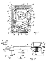
- a clothes dryer is indicated overall by 1 and comprises a cabinet 2 with an aperture 3, to coincide with which there is positioned a door 4 provided with usual seal gaskets 5 and in which a filter element 24A is disposed.
- the aperture 3 provides access to a usual drum 6 through which hot air circulation is generated to dry the clothes (not shown).
- Means are provided to produce this circulation and heating, said means being (in the example shown in Figure 1 and in Figures 2 to 5) a fan 7, a resistance element 8, a heat exchanger 9 and relative ducts 10A for feeding dry hot air C into the drum 6, 10B for removing the wet hot air U therefrom (provided partly within the door 4) and 10C for feeding cold air F to said fan 7.
- This air F originates from the heat exchanger 9 which in the example is of the countercurrent type.
- Cold air E originating from the outside of the cabinet 2 passes through it by being fed through a duct 12 by a second fan 13.
- the duct 12 opens again to the outside of the cabinet 2 via an aperture from which hot air G emerges.
- the water H contained in the moist hot air U condenses as this latter passes through the heat exchanger 9 and falls into a first collection vessel 15. This is connected via a pipe 16 to a pump 17 from which a further pipe 18 extends to terminate in a second collection vessel 19.
- the pipe 18 can be closed by a deflector or deviator (not shown) which connects the pump 17 to an aperture 20 opening into the cabinet 2 and which can be connected to a usual water discharge pipe.
- the vessel 19 (or upper vessel) is advantageously removable to allow the demineralized water contained in it to be used for known purposes.
- the machine 1 is a closed-circuit clothes dryer having for example four different drying levels selectable by the user from a usual control panel (not shown) connected to a known drying level selector 25.
- the machine 1 comprises means for monitoring and controlling the drying operation in accordance with the quantity of water present in at least one of said two vessels 15 and 19.
- drying selector 25 is connected via a connection 26 to a control unit 27 advantageously of microprocessor type.
- This latter is connected to means which measure the water variation in at least one of said two vessels 15 or 19 and is able to act on at least one of the means (for example the fans 7 and 13 and the resistance element 8) which circulate and heat the drying air.
- control unit 27 is connected to a contact 28 normally open during the drying stage and arranged to cooperate with a contact 29 connected to a plate 30 flexibly connected to an element 31 connected to earth.
- the plate 30 supports the vessel 15 and rests on an elastic element or compression spring 32 which rests on, and is rigid at its end 32 with, a fixed part 2A of the cabinet 2.
- the vessel 15 is also operationally connected (in any known manner) to a usual dynamometer 40.
- the control unit 27 is connected to said dynamometer 40 and is also operationally connected to a contactor 34 provided in the power feed line 35 to the motors 7A and 13A of the fans 7 and 13 and normally closed during machine operation.
- FIG. 2 also shows the power feed lines A for the various components shown in this figure.
- the pump 17 operates cyclically for a determined time period, to pump the water H removed form the clothes from the (lower) vessel 15 to the (higher) vessel 19 or to empty the lower vessel 15.
- each cyclic operation of the pump 17 provides corresponding (at least partial) emptying of the vessel 15.
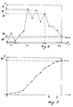
- the unit 27 measures the variation in the weight of said vessel by the dynamometer 40 (or equivalent means).
- this unit measures the variation in the water quantity Q present in said vessel and hence the variation in the water quantity removed from the clothes in the drum 6 during their drying.
- the unit 27 determines when the water quantity in the vessel 15 has reached a value substantially constant with time. Thus it determines when the drying of the clothes can be considered complete by virtue of the fact that no more water is discharged from them or that the water discharge corresponds only to the usual moisture naturally present in the clothes. Consequently the unit 27 operates the contactor 34 so that this opens. This interrupts power feed to the motors 7A and 13A and clothes drying is therefore halted.
- a further contact, not shown, also cuts off power feed to the resistance element 8 and pump 17.
- the described method for halting drying can also be applied, with obvious modifications, to evaluating the water quantity in the upper vessel 19 (if provided).
- the dynamometer 40 measures an increase in the water in this collection vessel and feeds data to the unit 27, these data lying substantially on a curve such as that shown in Figure 7.
- the value Q8 in Figure 7 corresponds to the value Q5 in Figure 6. With this modification when the unit 27 determines that the water quantity in the vessel 19 reaches and is maintained at said value Q8, it interrupts drying in the aforedescribed manner.
- the values Q5 and Q8 can also not correspond to complete water removal from the clothes present in the drum 6. In this respect, it is not important to determine this complete removal condition (ie it is not important to determine when there is no further production of water H from the heat exchanger 9), because this signifies that the clothes no longer possess the natural moisture which they normally retain and which is equal to about 7-8% of their total weight.
- a garment is considered dry when after washing and drying it returns to its original weight, which also comprises the natural moisture contained in it.
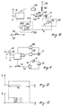
- FIGS 3 and 4 show further embodiments of the apparatus according to the invention using electrical components as measurement means for the water quantity in the vessel.
- the means enabling the unit 27 to determine the variation in the water quantity removed from the clothes and present in the vessel 15 (or in the vessel 19) consist of a capacitor 50 comprising two flat parallel plates 51 and 52, one of which (51) is connected to the unit 27 and the other (52) is connected to earth at 53.
- the capacitor is powered by the unit 27.
- the apparatus uses the variation in the capacitance of the capacitor 50 deriving from the variation in its dielectric constant.
- control unit 27 determines data lying on curves similar to those of the already described Figures 6 or 7, depending on whether the capacitor 50 is positioned in the lower collection vessel 15 or upper vessel 19.
- the means which determine the water quantity in the collection vessel 15 or 19 are a wire resistor 60 the ends 61 and 62 of which are connected to the unit 27 and to an earth point 63 respectively. This resistor is powered for example by said unit.
- the unit 27 determines water quantity in the vessel by the variation in the characteristics of the resistor 60.
- the ohmic value of this component varies according to the water level in the vessel.
- the extent of short-circuiting differs according to the water level reached, giving rise to corresponding different resistance values.
- the unit 27 evaluates (by means of known preset algorithms) the water quantity in the vessel (and hence the water quantity removed from the clothes during their drying), to operate the mobile contact 34 and halt the drying process in a manner similar to that already described.
- the measured data processed by the unit 27 and corresponding to the water quantity in the vessel lie on curves substantially similar to those of Figures 6 and 7, already described.
- FIG. 5 shows a further modification of the apparatus according to the invention in which parts corresponding to those of the already described figures are indicated by the same reference numerals.
- This apparatus uses electrical and mechanical components for measuring the water quantity in the vessel 15 or 19 and hence the water quantity removed from the clothes during their drying.
- the circuit for producing hot air is a usual refrigeration circuit comprising substantially a compressor 70, a condenser 71 and an evaporator 72, the compressor 70 being connected to a power feed line 73 which includes a contactor 74 normally closed during machine operation.
- the unit 27 is connected to one end 75 of a variable resistor 76, the other end 77 of which is connected to earth.
- the resistor is fed for example by said unit 27.
- the characteristics of the resistor 76 are varied by a lever 78 pivoted at 79 (this point can be rigid with a fixed part of the cabinet 2 of the machine 1 or with the structure of the vessel 15) and carrying at its free end a float 80 which rests on the surface 5 of the water present in the collection vessel (for example the lower vessel 15).
- the unit 27 converts this variation in the resistor characteristics into data (matching the curves 6 and 7) relative to the water quantity in the vessel and hence to the water quantity removed from the clothes during their drying.
- the unit 27 therefore opens the contactor 74 when the ohmic value of the resistor 76 remains constant with time. In this manner the operation of the compressor 70 stops, as does the drying process (the unit 27 also halts the motors of the usual air circulation fans).
- FIGS. 8 to 13 show other embodiments of the invention. In these figures, parts corresponding to those of the previously described figures are indicated by the same reference numerals.
- this determination is done by measuring the variation of at least one characteristic quantity of the pump during drying, as described hereinafter.
- the machine 1 comprises means for measuring the current absorbed by the pump 17 during evacuation of the water from the vessel 15 and means for measuring the gradient of the current absorbed by this pump during its operation. As described hereinafter, on the basis of this measurement the water quantity removed from the clothes during drying can be determined.
- the drying selector 25 is connected via the connection 26 to a control unit 27 analogous to that of Figures 2 to 5. This unit is connected to a usual timer 128 which provides for cyclic operation of the pump 17.
- this latter is usually set to operate for a time period (eg. 20-25 seconds) during which the pump 17 evacuates water from the vessel 15. This period is followed by a longer period (eg. 120-150 seconds) during which said pump is not in operation.
- the timer 128 therefore cyclically defines these periods of operation (or non-operation) of the pump 17.
- the pump 17 absorbs current from the mains, this absorption being proportional (as is well known) to the torque generated by the pump motor. This torque is proportional to the resistant couple offered by the water being evacuated from the vessel 15.
- the pump 17 is connected to means 129 which evaluate the mains current absorbed by the pump, said means being connected to another timer 130 which evaluates (in analog or digital form) the time for which the pump 17 actually operates on the water of the vessel 15 (ie evacuates it).
- the timer 130 can be either separate from the unit 27 or incorporated into it.
- control unit 27 also controls the contactor 34 which is connected into the line 35 powering the motors 7A and 13A of the fans 7 and 13, and is normally closed during operation of the machine 1.
- the unit 27 also operates in known manner (not shown) on the resistor 8.
- Figure 10 shows a schematic example of part of the circuit of Figure 9.
- This latter is connected to a comparator 141 arranged to compare a signal V corresponding to the drive torque generated by the pump motor with a threshold signal V S .
- the comparator 141 is connected to one input 142 of a logic operator (for example an AND gate) 142, the other input 144 of which is connected to an output of a further comparator 145.
- a logic operator for example an AND gate
- This latter has one input 146 connected to a point 147 between the contactor 140 and the pump 17, and the other input 148 connected to earth.
- the output of the AND gate 143 is connected to the unit 27.
- the pump 17 operates cyclically for a determined time period (T10 in Figure 5), to pump the water for example from the lower vessel 15 to the higher vessel 19 (or to empty the lower vessel 15).
- the unit 27 causes the timer 128 to close the contactor 140 in the line 17A so as to power said pump.
- the comparator 145 receives a signal from the input 146 which corresponds to the "operation enabled” state of the pump. At the output of this comparator there is a logic signal V A ( Figure 12) corresponding to said "enabling", this signal being fed to the input of the AND gate 143.
- the input 142 of this latter receives a further signal V C obtained from the comparator 141 by comparing the signal V with the threshold signal V S .
- V C is greater than zero (see Figure 13).
- V C is other than zero
- the AND gate 143 emits a logic signal 0.
- V C falls to zero
- this gate also emits a logic signal 0.
- the unit 27 detects that the pump 17 is operating on a (possibly variable) water quantity always greater than a minimum value (head) or zero. In the second case the unit 27 detects a negative variation of the pump drive torque and consequently that it is operating under no load (or on a water quantity less than said head).
- the unit 27 detects a negative variation in the water quantity removed from the clothes in the drum 6 during their drying.
- the unit 27 calculates (in accordance with a suitable known algorithm) that there is no further water in the clothes and that the drying stage has ended.
- the unit acts directly or indirectly on the contactors 140 and 34 to thus halt the pump 17 and the fans 7 and 13, and also cuts off power feed to the resistor 8.
- circuit of Figure 2 can operate on analog signals.
- the means 129 which calculate the absorbed current can be a usual ammeter while the timer 130 can be a usual threshold circuit arranged to sense when the analog signal originating from the ammeter falls below a threshold value.
- FIG 11 shows a modification of the apparatus according to the invention.
- parts corresponding to those of Figures 8 to 10 are indicated by the same reference numerals.
- the circuit for producing the hot air is the refrigeration circuit of Figure 5, comprising substantially a compressor 70, a condenser 71 and an evaporator 72, the compressor 70 being connected to a power feed line 73 which includes a contactor 74 normally closed during machine operation.
- the unit 27 is connected to the timer 128 operating on the pump 17. This latter is connected to a known tachometer dynamo 160 connected to the unit 27.
- the r.p.m. of the pump motor is continuously monitored by the unit 27.
- the unit 27 is able to calculate the variation in the water quantity drawn in by the pump from the collection vessel 15 and consequently the variation in the water quantity released by the clothes during their drying.
- the unit 27 allows the timer 128 to power the pump 17 (in the same manner as heretofore described in relation to Figures 8, 9 and 10), so causing it to operate.
- This variation is measured by the tachometer dynamo, which feeds its data to the control unit 27.
- this latter calculates the mains current absorbed by the pump 17 on the basis of said r.p.m., this current being inversely proportional to said r.p.m. and thus directly proportional to the water quantity released from the clothes during their drying.
- the unit 27 thus detects a negative variation with time in the current absorbed by the pump and halts drying (by acting for example on the compressor 70 and on the timer 128) when this current remains substantially constant with time or falls below an appropriate threshold valve corresponding to a pump r.p.m. able to remove from the vessel 15 the usual water head always present in said vessel.
- the water quantity removed from the clothes during their drying is calculated from the energy transferred to mobile means disposed in a pipe upstream or downstream of the pump 17.
- the machine 1 comprises means for measuring the energy transferred by the water evacuated by the pump 17 from the vessel 15, to a mobile member disposed (in the example under examination) in the pipe 18 and means for measuring the gradient of the variation in this transferred energy during the operation of the clothes dryer 1.
- the drying selector 25 is connected to a control unit 27 similar to that described in the preceding figures. This unit is connected to the timer 128 to determine cyclic operation of the pump 17, as heretofore described.
- the timer 128 therefore defines cyclic periods of operation (or non-operation) of the pump 17, one of which is shown in the previously described Figure 12.
- the pump 17 is connected to a comparator 229 (or similar member or circuit), one input of which is connected to a tachometer dynamo 230 (or another similar member).
- the other input of the comparator 229 receives a suitably chosen reference signal V K .
- the tachometer dynamo measures the rotational speed of an idle shaft 231 on which there is fixed an impeller 232 positioned in the pipe 18 (which can be the discharge pipe or the pipe carrying the water from the vessel 15 to the vessel 19).
- the shaft 231 at least partly projects into this pipe. This is achieved for example by forming a hole (not shown) in this latter and providing usual seal means about said shaft.
- the control unit 27 is also operationally connected to the contactor 34 which is incorporated in the line 35 powering the motors 7A and 13A of the fans 7 and 13 and is normally closed during operation of the machine 1.
- the unit 27 also operates in known manner (not shown) as already stated on the power supply to the pump 17 and to the resistor 8.
- the pump 17 operates cyclically for a determined time period (T10 in Figure 12), to pump the water for example from the lower vessel 15 to the higher vessel 19 (or to empty the lower vessel 15).
- the unit 27 causes the timer 128 to close a contactor (not shown) in the line powering said pump. This pump therefore rotates.
- the rotational speed of the shaft 231 of the impeller 232 is measured in known manner by the dynamo 230, which generates electrical signals V R based on this measurement.
- the signals V R are compared in the comparator 229 with the reference or threshold signals V K . As a result of this comparison the comparator generates signals V O (logic signals in the example of Figure 15), which are fed to the control unit 27.
- the water flow rate to the pipe 18 is therefore high.
- the water at this flow rate strikes the impeller to rotate it.
- the rotational speed of the shaft 231 of the impeller 232 is measured by the tachometer dynamo 230 which generates the signals V R as stated. These signals are compared with the signals V K to generate an output from the comparator 229 which is "high" (equal to 1). This high output or level 1 remains for the entire stage F1,
- the water quantity in the clothes begins to fall. Consequently the water flow rate through the pipe 18 also falls. Specifically, during some periods T20 the flow rate is still sufficient for the signal V R generated by the dynamo 230 to exceed the signal V K . Consequently during these periods the output V O is equal to 1. During other periods T30, the flow rate is insufficient and the impeller does not rotate. During these periods the signal V R is less than V K and therefore V O is zero.
- the unit 27 calculates (again on the basis of suitable known comparison algorithms) that there is no more water in the clothes contained in the drum 6, or rather that they contain only a minimum quantity equivalent to their natural water content.
- the unit 27 ascertains that the pump 17 is operating on a (possibly variable) water quantity in the vessel 15 which always exceeds a minimum value (head) or zero, this corresponding to a large water quantity removed from the clothes during their drying.
- the unit 27 detects a negative variation in the flow rate of the water fed by the pump 17 into the pipe 18, ie a negative gradient for the energy transferred by the fluid to the impeller 232. In this case the unit 27 ascertains a reduction in the discharge of water from the clothes.
- control unit 27 calculates (on the basis of suitable known comparison algorithms) that there is no more water in the clothes and that the drying stage has thus terminated.
- the unit operates the contactor 34 to open it and thus halt the fans 7 and 13.
- the unit 27 also switches off the power feed to the resistor 8 and to the pump 17, which stops.
- circuit of Figure 15 can operate on analog signals.
- a usual threshold circuit can be used able to determine when the analog signal from the dynamo 230 falls below a threshold value.
- FIG 16 schematically illustrates a modification of the apparatus according to the invention.
- parts corresponding to those of the already described figures are indicated by the same reference numerals.
- the unit 27 is again connected to a variable resistor 225 on which there operates a mobile element 256 connected by an arm 257 to a mobile flap 258 which intercepts the pipe 18. This resistor is fed by the unit 27.
- the water passing through the pipe 18 transfers energy to the flap 258, which then moves to a greater or lesser extent from a rest position in which it lies on an element 29 and completely closes the pipe 18.
- the energy transferred to the flap 258 varies according to the water flow through the pipe 18, and is determined by a variation in the ohmic value of the resistor 55. This variation is monitored by the unit 27.
- the flap 258 only minimally closes the pipe 18 (flap in a substantially vertical position in Figure 16). Under these conditions the ohmic value of the resistor 255 is high.
- the unit 27 detects this negative variation in the characteristics of the resistor 255 and halts drying (acting for example on the compressor 70 and timer 128) when this resistance remains substantially constant with time or when it falls below a suitable threshold value corresponding to practically zero energy transferred by the water to the flap 258.
- a by-pass 280 provided with its own flap 281 mobile in opposition to the flap 258 is installed on the pipe 18. This by-pass allows natural gravity return of the water lying downstream of the flap 258 when drying has terminated, this water providing the usual head present in the vessel 15.
- the apparatus of this embodiment of the invention can take a different form from those described herein.
- One of these modified forms consists for example of using a normal flowmeter inserted into the pipe 18. This meter measures the water flow rate through the pipe on the basis of the transfer by the water of at least part of the energy transferred to the water by the pump. On the basis of said flow variation the unit 27 determines the variation in the water discharged by the clothes present in the drum 6.
- the method and apparatus of the invention determine when the drying process is complete and when the means which implement it have to be halted.
- This method can be implemented in a clothes dryer of any type without having to modify its drum, provided the machine comprises a closed-cycle circuit incorporating a heat exchanger for recovering the water removed from the clothes during the drying process.
- the determination of the water quantity discharged by the clothes can by implemented discontinuously or continuously during the operation of the clothes dryer or the like.
Landscapes
- Engineering & Computer Science (AREA)
- Textile Engineering (AREA)
- Detail Structures Of Washing Machines And Dryers (AREA)
- Control Of Washing Machine And Dryer (AREA)
Claims (43)
- Procédé pour commander le processus de séchage dans un sèche-linge, une machine lave-linge/sèche-linge-linge ou similaires, du type qui comprend un tambour, des moyens habituels pour produire une circulation d'air chaud à travers le tambour afin de sécher les vêtements qui sont contenus dans celui-ci, des moyens pour refroidir ledit air, au moins un réservoir ou récipient pour recueillir l'eau enlevée desdits vêtements par l'air et condensée sur l'un ou plusieurs desdits moyens pendant ladite circulation, et une pompe pour enlever l'eau dudit récipient, avantageusement de façon cyclique, caractérisé en ce que l'on mesure, dans le but de commander le processus de séchage des vêtements (5), la quantité d'eau libérée par les vêtements pendant une période prédéterminée (T₁, T₁₀) pendant leur séchage, et on fournit un signal pour arrêter la machine si la mesure obtenue est inférieure à une valeur prédéterminée.
- Procédé selon la revendication 1, caractérisé en ce que la quantité d'eau libérée par les vêtements est mesurée directement en mesurant la quantité d'eau condensée qui est recueillie dans le récipient de collecte (15, 19).
- Procédé selon la revendication 1, caractérisé en ce que la quantité d'eau relâchée par les vêtements est mesurée indirectement.
- Procédé selon la revendication 2, caractérisé en ce que l'eau présente dans le récipient de collecte (15, 19) est mesurée de façon discontinue pendant le fonctionnement de la machine (1).
- Procédé selon la revendication 2, caractérisé en ce que l'eau présente dans le récipient de collecte (15, 19) est mesurée en continu pendant le fonctionnement de la machine (1).
- Procédé selon la revendication 2, caractérisé en ce que l'on coupe l'alimentation puissance vers les moyens (7, 8, 70) pour assurer la circulation d'air chaud à travers le tambour, les moyens de refroidissement d'air (13) et la pompe (17) en se basant sur les données mesurées relatives à la quantité d'eau présente dans le récipient de collecte (15, 19) et en relation directe avec la quantité d'eau libérée par les vêtements.
- Procédé selon la revendication 2, caractérisé en ce que la quantité d'eau dans le récipient de collecte (15, 19) est évaluée sur la base du poids d'eau.
- Procédé selon la revendication 2, caractérisé en ce que la quantité d'eau dans le récipient de collecte (15, 19) est évaluée sur la base de la détermination de modifications des caractéristiques d'éléments électriques fonctionnellement en relation avec l'eau présente dans le récipient (15, 19).
- Procédé selon la revendication 3, caractérisé en ce que pour évaluer indirectement d'eau déchargée par les vêtements, on surveille le courant absorbé par la pompe (17) pendant l'évacuation de l'eau hors du récipient de collecte (15), on détermine sa variation pendant le séchage des vêtements, et en se basant sur cette détermination, on agit sur les moyens (16, 13, 8 ; 70) pour assurer une circulation d'air chaud à travers le tambour (6) et pour assurer le refroidissement de l'air afin d'arrêter le processus de séchage lorsque le gradient de cette variation est négatif et que ledit courant reste sensiblement constant dans le temps.
- Procédé selon la revendication 9, caractérisé en ce que la variation du courant absorbé par la pompe (17) est déterminée de façon numérique.
- Procédé selon la revendication 9, caractérisé en ce que la variation du courant absorbé par la pompe (17) est déterminée de façon analogique.
- Procédé selon la revendication 9, caractérisé en ce que la variation du courant absorbé par la pompe (17) est déterminée en mesurant la variation d'une quantité qui est fonctionnellement associée audit courant.
- Procédé selon la revendication 12, caractérisé en ce que la quantité associée au courant absorbé par la pompe (17) est le couple produit par son moteur.
- Procédé selon la revendication 12, caractérisé en ce que la quantité associée au courant absorbé par la pompe (17) est la vitesse de rotation de son moteur.
- Procédé selon la revendication 3, caractérisé en ce que pour évaluer indirectement la quantité d'eau déchargée par les vêtements, on utilise au moins une partie de l'énergie transférée par la pompe (17) à l'eau pendant son évacuation hors du récipient de collecte pour déplacer un organe (232, 258) disposé dans un tube (18) raccordé à ladite pompe (17), ladite énergie variant pendant le processus de séchage et tendant sensiblement vers zéro vers la fin de ce processus, la variation de ladite énergie étant représentative de la décharge d'eau hors des vêtements pendant leur séchage et par conséquent de leur état de sécheresse, le séchage étant arrêté lorsque le gradient de ladite variation est négatif et que l'énergie transférée reste sensiblement constante dans le temps.
- Procédé selon la revendication 15, caractérisé en ce que la variation de l'énergie transférée à l'élément mobile (232 ; 258) est déterminée de façon numérique.
- Procédé selon la revendication 15, caractérisé en ce que la variation de l'énergie transférée à l'organe mobile (232 ; 258) est déterminée de façon analogique.
- Procédé selon la revendication 15, caractérisé en ce que la variation de l'énergie transférée à l'organe mobile (232 ; 258) est déterminée en mesurant la situation de repos dudit organe.
- Procédé selon l'une quelconque des revendications 15 à 18, caractérisé en ce que la variation de l'énergie transférée à l'organe mobile (232 ; 258) est évaluée sur la base de la variation du débit d'eau à travers le tube dans lequel est disposé ledit organe.
- Sèche-linge, machine lave-linge/sèche-linge ou similaire, comprenant un tambour, des moyens habituels pour produire une circulation d'air chaud à travers le tambour afin de sécher les vêtements qui y sont contenus, ledit air étant ensuite refroidi, au moins un réservoir ou récipient pour recueillir l'eau enlevée desdits vêtements par ledit air et condensée sur l'un desdits moyens pendant ladite circulation, et une pompe pour enlever ladite eau hors du récipient, avantageusement de façon cyclique, le procédé revendiqué dans les revendications précédentes étant mis en oeuvre dans ladite machine, cette machine étant caractérisée en ce qu'elle comprend des moyens de mesure (40, 50, 60, 76, 80 ; 129, 130, 160 ; 230, 235) pour mesurer la quantité d'eau libérée depuis les vêtements pendant leur séchage et pour produire des signaux basés sur cette mesure, lesdits signaux étant alimentés à une unité de commande (27) qui est connectée à l'un au moins des moyens (7, 8 ; 13 ; 70) pour chauffer l'air de séchage et pour produire la circulation d'air à travers le tambour, et pour réchauffer ledit air, ladite unité (27) surveillant la variation de ladite quantité d'eau mesurée et agissant sur ledit moyen lorsque ladite variation a un gradient négatif et lorsque les signaux provenant des moyens de mesure (40, 50, 60, 76, 80 ; 129, 130, 160 ; 230, 235) correspondent à une quantité d'eau mesurée qui est constante dans le temps.
- Machine selon la revendication 20, caractérisée en ce que les moyens de mesure (40, 50... ; 230, 255) sont du type électrique et/ou mécanique.
- Machine selon la revendication 21, caractérisée en ce que les moyens de mesure sont un dynamomètre (40) connecté de toute manière connue au récipient de collecte (15, 19) pour l'eau condensée, qui est supporté par une plaque (30) reposant sur un organe élastique (32) fixé sur une partie fixe de la machine (1).
- Machine selon la revendication 22, caractérisée en ce que la plaque (30) est associée à un point de mise à la terre (31) au moyen d'une connexion flexible, ladite plaque comprenant un contact (29) agencé de manière à se fermer sur un contact fixe (28) associé à l'unité de commande (27).
- Machine selon la revendication 21, caractérisée en ce que les moyens de mesure sont une capacité introduite dans le récipient (15, 19).
- Machine selon la revendication 24, caractérisée en ce que la capacité (50) est formée à partir de plaques planes parallèles (51, 52), dont l'une (51) est connectée à l'unité de commande (27) et d'autre à un point de mise à la terre (53).
- Machine selon la revendication 21, caractérisée en ce que les moyens de mesure sont une résistance (60), avantageusement du type à fil, introduite dans le récipient de collecte (15, 19), ladite résistance (60) ayant une extrémité (61) connectée à l'unité de commande (27) et l'autre extrémité (62) à un point de mise à la terre (63).
- Machine selon la revendication 21, caractérisée en ce que les moyens de mesure sont une résistance variable (76) connectée à une extrémité (75) à l'unité de commande (27) et à son autre extrémité à un point de mise à la terre (77), ladite résistance étant connectée à un levier (78) qui porte à une extrémité un flotteur (80) reposant sur la surface (5) de l'eau dans le récipient (15, 19), ledit levier (78) agissant sur ladite résistance (76) d'une manière telle que sa valeur ohmique varie tandis que la quantité d'eau dans le récipient varie.
- Machine selon les revendications 20 et 21, caractérisée en ce que les moyens de mesure (129, 139, 60) sont agencés pour mesurer le courant absorbé par la pompe (17) pendant l'évacuation de l'eau hors du récipient de collecte (15) et pour produire des signaux sur la base de cette mesure.
- Machine selon la revendication 28, caractérisée en ce que les moyens de mesure (129) sont un ampèremètre.
- Machine selon la revendication 29, caractérisé en ce que l'ampèremètre (129) est raccordé à un circuit de seuil (130) raccordé à l'unité de commande (27).
- Machine selon la revendication 28, caractérisée en ce que les moyens de mesure (129) sont un circuit de surveillance et de comparaison qui traite un signal (Vc) proportionnel au couple moteur et pris aux bornes du moteur de la pompe (17), et un signal (VA) représentatif de la durée de l'alimentation en puissance à ladite pompe, ledit circuit définissant la variation du signal représentatif du couple moteur (Vc) et ainsi du courant absorbé par la pompe (17) dans le temps, pour fournir alors un signal correspondant à cette variation à l'unité de commande (27), laquelle agit sur la base de ce signal sur l'un au moins des moyens (7, 8, 13, 70) produisant la circulation d'air à travers le tambour (6) et réchauffant l'air, et sur la pompe (17).
- Machine selon la revendication 28, caractérisée en ce que les moyens de mesure (129) sont un comparateur (141) qui reçoit depuis le moteur habituel de la pompe (17) un signal (V) correspondant au couple qu'il produit, et qui compare ce signal (V) avec un signal de seuil (VS), ledit comparateur (141) produisant sur la base de cette comparaison un signal (Vc) qui est fourni à une entrée (142) d'un circuit logique (143) agencé de façon à comparer ce signal (Vc) sensiblement correspondant au couple du moteur de la pompe (17) produit en présence d'au moins une charge convenable d'eau dans le récipient de collecte (15), à un signal (VA) indiquant la présence de l'alimentation en puissance de la pompe (17), ledit circuit logique produisant une valeur 1 ou 0 selon que cette comparaison indique une évacuation d'eau valide hors dudit récipient, ou une évacuation d'eau qui est nulle ou qui est inférieure à la charge habituelle toujours présente dans le récipient, ladite valeur 1 ou 0 étant fournie à l'unité de commande (27).
- Machine selon la revendication 28, caractérisée en ce que les moyens de mesure sont une dynamo tachométrique (60) connectée au moteur habituel de la pompe (17).
- Machine selon les revendications 20 et 21, caractérisée en ce qu'elle comprend au moins un organe mobile (232, 258) disposé dans un tube (18) raccordé à la pompe (17), et des moyens de mesure (230, 255) pour mesurer l'énergie transférée par l'eau condensée pendant son passage à travers ledit tube à l'organe mobile (232, 258) et pour produire des signaux électriques en se basant sur cette mesure, lesdits signaux étant fournis à l'unité de commande (27).
- Machine selon la revendication 34, caractérisée en ce que les moyens de mesure (230) sont une dynamo tachométrique, ou un dispositif semblable.
- Machine selon la revendication 35, caractérisée en ce que la dynamo tachométrique (230) est connectée à un circuit de seuil (229) connecté à l'unité de commande (27).
- Machine selon la revendication 35, caractérisée en ce que la dynamo tachométrique (230) est raccordée à un élément comparateur ou similaire (229) connecté à l'unité de commande (27).
- Machine selon les revendications 34 et 35, caractérisée en ce que l'élément mobile (232) est une hélice disposée à l'intérieure du tube (18) raccordé à la pompe (7), ladite hélice étant associée à un arbre fou qui émerge au moins en partie dudit tube et qui est fonctionnellement relié à la dynamo tachométrique (230).
- Machine selon la revendication 34, caractérisée en ce que l'élément mobile est un élément (258) agencé de façon à recouper le tube (18) raccordé à la pompe (17), ledit élément (258) étant raccordé à un organe (256) qui régule une résistance variable (255), dont les extrémités sont connectées à l'unité de commande (27).
- Machine selon la revendication 34, caractérisée en ce que les moyens de mesure sont un débitmètre disposé dans le tube (18) raccordé à la pompe (17).
- Machine selon la revendication 20, caractérisée en ce que l'unité de commande (27) est un circuit à microprocesseur.
- Machine selon la revendication 20, caractérisée en ce que l'unité de commande (27) agit sur l'alimentation en puissance (35, 73) des moyens (7, 8, 13,70) destinés à faire circuler, à chauffer et à refroidir l'air utilisé pour sécher les vêtements dans le tambour (6) de la machine (1), et sur l'alimentation en puissance de la pompe (17).
- Machine selon la revendication 42, caractérisée en ce que l'unité de commande (27) commande un contacteur (34, 74) agencé pour ouvrir ou fermer une ligne d'alimentation en puissance (35, 73) vers les moyens (7, 8, 13, 70) destinés à faire circuler, à réchauffer et à refroidir l'air utilisé pour sécher les vêtements dans le tambour (6) de la machine (1), ladite unité (27) commandant le fonctionnement d'un temporisateur (128) qui permet l'alimentation en puissance de la pompe (17).
Applications Claiming Priority (2)
| Application Number | Priority Date | Filing Date | Title |
|---|---|---|---|
| IT2178990 | 1990-10-18 | ||
| IT02178990A IT1246211B (it) | 1990-10-18 | 1990-10-18 | Metodo ed apparecchiatura per controllare la fase di asciugatura in una macchina asciugabiancheria, lavabiancheria o similare. |
Publications (3)
| Publication Number | Publication Date |
|---|---|
| EP0481561A2 EP0481561A2 (fr) | 1992-04-22 |
| EP0481561A3 EP0481561A3 (en) | 1992-09-02 |
| EP0481561B1 true EP0481561B1 (fr) | 1995-03-22 |
Family
ID=11186874
Family Applications (1)
| Application Number | Title | Priority Date | Filing Date |
|---|---|---|---|
| EP91202645A Expired - Lifetime EP0481561B1 (fr) | 1990-10-18 | 1991-10-11 | Procédé et dispositif pour contrôler la phase de séchage dans un sèche-linge, une machine à laver ou similaire |
Country Status (6)
| Country | Link |
|---|---|
| US (1) | US5228212A (fr) |
| EP (1) | EP0481561B1 (fr) |
| JP (1) | JPH04270000A (fr) |
| DE (1) | DE69108342T2 (fr) |
| ES (1) | ES2072532T3 (fr) |
| IT (1) | IT1246211B (fr) |
Families Citing this family (39)
| Publication number | Priority date | Publication date | Assignee | Title |
|---|---|---|---|---|
| JP3022150B2 (ja) * | 1994-04-27 | 2000-03-15 | 三洋電機株式会社 | 衣類乾燥機 |
| FR2729470A1 (fr) * | 1995-01-17 | 1996-07-19 | Ciapem | Dispositif de mesure du degre de sechage dans un seche-linge |
| US6127663A (en) * | 1998-10-09 | 2000-10-03 | Ericsson Inc. | Electronics cabinet cooling system |
| IT1305556B1 (it) * | 1998-12-03 | 2001-05-09 | Electrolux Zanussi Elettrodome | Metodo per controllare l'asciugatura del carico inun'asciugabiancheria o simile |
| DE19960217C2 (de) * | 1999-12-14 | 2003-04-10 | Whirlpool Co | Kondensations-Wäschetrockner mit Wärmetauscher und Kondensat-Auffangeinrichtung |
| US6199300B1 (en) | 2000-03-01 | 2001-03-13 | Whirlpool Corporation | Method for energy efficient control of a dryer of clothes |
| DE10260149A1 (de) | 2002-12-20 | 2004-07-01 | BSH Bosch und Siemens Hausgeräte GmbH | Vorrichtung zur Bestimmung des Leitwertes von Wäsche, Wäschetrockner und Verfahren zur Verhinderung von Schichtbildung auf Elektroden |
| US8567091B2 (en) * | 2002-12-24 | 2013-10-29 | Lg Electronics Inc | Automatic dryer control based on load information |
| KR100955484B1 (ko) * | 2003-04-30 | 2010-04-30 | 삼성전자주식회사 | 세탁기 및 그 건조 제어방법 |
| KR100595188B1 (ko) * | 2003-09-24 | 2006-07-03 | 엘지전자 주식회사 | 응축식 의류건조기의 응축기 |
| US7020985B2 (en) * | 2004-03-26 | 2006-04-04 | Whirlpool Corporation | Multiple outlet air path for a clothes dryer |
| KR101093886B1 (ko) | 2004-05-20 | 2011-12-13 | 엘지전자 주식회사 | 건조기의 응축수 이동구조 |
| KR101084121B1 (ko) * | 2004-07-28 | 2011-11-16 | 엘지전자 주식회사 | 건조기 일체형 세탁기의 메뉴 구성방법 |
| EP2290144A1 (fr) * | 2005-01-14 | 2011-03-02 | Electrolux Home Products Corporation N.V. | Appareil de traitement d'un article textile avec un dispositif de nettoyage par ultrason |
| DE102005013051A1 (de) * | 2005-03-18 | 2006-09-21 | BSH Bosch und Siemens Hausgeräte GmbH | Kondensations-Wäschetrockner |
| ES2281239B1 (es) * | 2005-03-23 | 2008-08-16 | Ibai, S. Coop. | Armario de desarrugado y secado de ropa. |
| KR101235193B1 (ko) * | 2005-06-13 | 2013-02-20 | 삼성전자주식회사 | 세탁기 및 그 제어방법 |
| AU2007203890B2 (en) * | 2006-01-03 | 2010-07-15 | Lg Electronics Inc. | Dryer |
| DE102006029960A1 (de) * | 2006-06-29 | 2008-01-03 | BSH Bosch und Siemens Hausgeräte GmbH | Trockner mit verringerter Geräuschentwicklung, hierfür geeignetes Gebläse und Läuferrad sowie Verfahren zur Herstellung des Läuferrades |
| KR101203840B1 (ko) * | 2006-12-14 | 2012-11-21 | 엘지전자 주식회사 | 세탁장치 및 그 제어방법 |
| ITTO20080153A1 (it) * | 2008-02-29 | 2009-09-01 | Indesit Co Spa | Metodo per il controllo di parametri operativi in una macchina asciugatrice o lava-asciugatrice e macchina utilizzante detto metodo |
| KR101072023B1 (ko) | 2008-09-26 | 2011-10-10 | 엘지전자 주식회사 | 액체 저장 용기 및 그를 포함하는 의류 건조기 |
| NL2003076C2 (nl) * | 2009-06-23 | 2010-12-27 | Andries Koops | Wasdroger. |
| EP2284310B1 (fr) * | 2009-08-12 | 2014-07-09 | Electrolux Home Products Corporation N.V. | Sèche-linge à tambour avec pompe à chaleur et procédé pour faire fonctionner une pompe à chaleur pour un sèche-linge |
| EP2386678B1 (fr) * | 2010-05-10 | 2016-11-30 | Whirlpool Corporation | Sèche-linge à cycle fermé et procédé de séchage de vêtements utilisant un tel sèche-linge |
| KR20110132151A (ko) * | 2010-06-01 | 2011-12-07 | 삼성전자주식회사 | 건조기 및 건조도 측정 방법 |
| US8387274B2 (en) * | 2010-07-16 | 2013-03-05 | Whirlpool Corporation | Variable airflow in laundry dryer having variable air inlet |
| KR20120088034A (ko) * | 2010-10-19 | 2012-08-08 | 엘지전자 주식회사 | 건조겸용 세탁장치 및 건조완료 판단방법 |
| US20130032298A1 (en) * | 2011-08-01 | 2013-02-07 | Putt Michael D | Automated method for waste dehydration rate assessment through condensate monitoring |
| KR101980900B1 (ko) * | 2012-07-13 | 2019-05-22 | 삼성전자주식회사 | 수위감지장치 및 이를 가지는 의류건조기 |
| DE102012216397A1 (de) * | 2012-09-14 | 2014-03-20 | BSH Bosch und Siemens Hausgeräte GmbH | Kondensationstrockner mit Ermittlung der Beladung sowie Verfahren zu seinem Betrieb |
| KR102057859B1 (ko) | 2013-01-25 | 2019-12-20 | 엘지전자 주식회사 | 의류처리장치 |
| EP3039182B1 (fr) * | 2013-08-29 | 2017-09-27 | Arçelik Anonim Sirketi | Sèche-linge à pompe à chaleur muni d'un système de surveillance du degré de séchage |
| DE102015201831A1 (de) * | 2015-02-03 | 2016-08-04 | BSH Hausgeräte GmbH | Verfahren zur Ermittlung von Wäscheeigenschaften und hierfür geeigneter Kondensationstrockner |
| DE102016210265A1 (de) * | 2016-06-10 | 2017-12-14 | BSH Hausgeräte GmbH | Verfahren zur Ermittlung der Endrestfeuchte in einem Kondensationstrockner sowie hierfür geeigneter Kondensationstrockner |
| CN110226004B (zh) * | 2016-12-28 | 2021-11-12 | 伊莱克斯家用电器股份公司 | 具有可靠的干燥周期信息的器具 |
| US10669668B2 (en) | 2017-11-28 | 2020-06-02 | Mark Goodson | Clothes dryer fire reduction system |
| CN111434842A (zh) * | 2018-12-26 | 2020-07-21 | 青岛海尔滚筒洗衣机有限公司 | 一种干衣/护理设备的储水盒、设备及控制方法 |
| CN116815482A (zh) * | 2022-03-21 | 2023-09-29 | 青岛海尔洗衣机有限公司 | 一种具有判干装置的干衣机及其判干方法 |
Family Cites Families (8)
| Publication number | Priority date | Publication date | Assignee | Title |
|---|---|---|---|---|
| US3186106A (en) * | 1961-02-06 | 1965-06-01 | Whirlpool Co | Drier having flow rate-responsive control means |
| DE2232911B1 (de) * | 1972-07-05 | 1973-09-27 | Licentia Patent-Verwaltungs-Gmbh, 6000 Frankfurt | Waschetrockner mit im Trockenluft strom angeordneter Kondensations einrichtung |
| DE2256404C2 (de) * | 1972-11-17 | 1974-01-31 | Licentia Patent-Verwaltungs-Gmbh, 6000 Frankfurt | Wäschetrockner mit im Trockenluftstrom angeordneter Kondensationseinrichtung |
| DE3015428C2 (de) * | 1980-04-22 | 1982-04-22 | Ranco Inc., 43201 Columbus, Ohio | Trommeltrockner zum Trocknen von Wäsche |
| FR2497243A1 (fr) * | 1980-12-30 | 1982-07-02 | Carpano & Pons | Dispositif de commande d'un sechoir a linge |
| US4546554A (en) * | 1982-11-30 | 1985-10-15 | Cissell Manufacturing Company | Clothes dryer having variable position motor and moisture sensor |
| US4738034A (en) * | 1985-12-16 | 1988-04-19 | Kabushiki Kaisha Toshiba | Drying machine |
| US4827627A (en) * | 1988-02-22 | 1989-05-09 | American Dryer Corporation | Apparatus and method for controlling a drying cycle of a clothes dryer |
-
1990
- 1990-10-18 IT IT02178990A patent/IT1246211B/it active IP Right Grant
-
1991
- 1991-10-11 ES ES91202645T patent/ES2072532T3/es not_active Expired - Lifetime
- 1991-10-11 EP EP91202645A patent/EP0481561B1/fr not_active Expired - Lifetime
- 1991-10-11 DE DE69108342T patent/DE69108342T2/de not_active Expired - Fee Related
- 1991-10-15 US US07/776,157 patent/US5228212A/en not_active Expired - Lifetime
- 1991-10-18 JP JP3270888A patent/JPH04270000A/ja active Pending
Also Published As
| Publication number | Publication date |
|---|---|
| IT9021789A1 (it) | 1992-04-18 |
| EP0481561A3 (en) | 1992-09-02 |
| IT1246211B (it) | 1994-11-16 |
| DE69108342T2 (de) | 1995-09-28 |
| IT9021789A0 (it) | 1990-10-18 |
| DE69108342D1 (de) | 1995-04-27 |
| JPH04270000A (ja) | 1992-09-25 |
| EP0481561A2 (fr) | 1992-04-22 |
| ES2072532T3 (es) | 1995-07-16 |
| US5228212A (en) | 1993-07-20 |
Similar Documents
| Publication | Publication Date | Title |
|---|---|---|
| EP0481561B1 (fr) | Procédé et dispositif pour contrôler la phase de séchage dans un sèche-linge, une machine à laver ou similaire | |
| US7971371B2 (en) | Apparatus and method for controlling a clothes dryer | |
| TWI900355B (zh) | 衣物處理裝置的控制方法、裝置、衣物處理裝置及儲存介質 | |
| RU2459020C2 (ru) | Способ управления барабанной сушилкой для белья | |
| US5564831A (en) | Method and apparatus for detecting the temperature of an environment | |
| US5560124A (en) | Automatic cycle terminator for dryers | |
| US5006778A (en) | Motor diagnostics and electronic control for a clothers dryer | |
| US5408716A (en) | Fluid-handling machine incorporating a closed loop system for controlling liquid load | |
| US6158148A (en) | Method for detecting impermissible operating states in a hot-air clothes dryer, and a dryer with such a detection method | |
| EP1818441B1 (fr) | Mode de séchage pour sèche-linge automatique | |
| CA1238390A (fr) | Regulateur thermostatique pour seche-linge | |
| US4112589A (en) | Control system for drier | |
| US5166592A (en) | Motor diagnostics and electronic control for a clothes dryer | |
| EP1473403A1 (fr) | Machine à laver | |
| US5454171A (en) | Clothes dryer automatically determining a period of crease-preventing, intermittent operation | |
| US3028680A (en) | Method and apparatus for controlling laundry dryers | |
| US20120084997A1 (en) | Method to detect an end of cycle in a clothes dryer | |
| CN115323738A (zh) | 确定运行参数的方法、衣物处理设备及存储介质 | |
| CN214300909U (zh) | 一种回风道装置及具有其的衣物处理设备 | |
| EP1014845B1 (fr) | Lave-vaisselle a sonde thermique assurant la regulation de l'humidite | |
| CA2032857A1 (fr) | Diagnostique et controle electronique d'elements chauffant de seche-linge | |
| CN111235848A (zh) | 一种衣物烘干设备的控制方法及衣物烘干设备 | |
| US3186106A (en) | Drier having flow rate-responsive control means | |
| EP0573703A1 (fr) | Procédé pour optimiser le séchage dans un sèche linge ou similaire et machine utilisant ce procédé | |
| US11846064B2 (en) | Lint filter clogging detection in a dryer appliance using compressor temperature and referigerant mass flow |
Legal Events
| Date | Code | Title | Description |
|---|---|---|---|
| PUAI | Public reference made under article 153(3) epc to a published international application that has entered the european phase |
Free format text: ORIGINAL CODE: 0009012 |
|
| AK | Designated contracting states |
Kind code of ref document: A2 Designated state(s): DE ES FR GB |
|
| PUAL | Search report despatched |
Free format text: ORIGINAL CODE: 0009013 |
|
| AK | Designated contracting states |
Kind code of ref document: A3 Designated state(s): DE ES FR GB |
|
| RAP1 | Party data changed (applicant data changed or rights of an application transferred) |
Owner name: WHIRLPOOL EUROPE B.V. |
|
| 17P | Request for examination filed |
Effective date: 19930301 |
|
| 17Q | First examination report despatched |
Effective date: 19940707 |
|
| GRAA | (expected) grant |
Free format text: ORIGINAL CODE: 0009210 |
|
| AK | Designated contracting states |
Kind code of ref document: B1 Designated state(s): DE ES FR GB |
|
| REF | Corresponds to: |
Ref document number: 69108342 Country of ref document: DE Date of ref document: 19950427 |
|
| ET | Fr: translation filed | ||
| REG | Reference to a national code |
Ref country code: ES Ref legal event code: FG2A Ref document number: 2072532 Country of ref document: ES Kind code of ref document: T3 |
|
| PLBE | No opposition filed within time limit |
Free format text: ORIGINAL CODE: 0009261 |
|
| STAA | Information on the status of an ep patent application or granted ep patent |
Free format text: STATUS: NO OPPOSITION FILED WITHIN TIME LIMIT |
|
| 26N | No opposition filed | ||
| PGFP | Annual fee paid to national office [announced via postgrant information from national office to epo] |
Ref country code: GB Payment date: 19961002 Year of fee payment: 6 |
|
| PGFP | Annual fee paid to national office [announced via postgrant information from national office to epo] |
Ref country code: FR Payment date: 19961009 Year of fee payment: 6 |
|
| PGFP | Annual fee paid to national office [announced via postgrant information from national office to epo] |
Ref country code: ES Payment date: 19961030 Year of fee payment: 6 |
|
| PGFP | Annual fee paid to national office [announced via postgrant information from national office to epo] |
Ref country code: DE Payment date: 19961221 Year of fee payment: 6 |
|
| PG25 | Lapsed in a contracting state [announced via postgrant information from national office to epo] |
Ref country code: GB Free format text: LAPSE BECAUSE OF NON-PAYMENT OF DUE FEES Effective date: 19971011 |
|
| PG25 | Lapsed in a contracting state [announced via postgrant information from national office to epo] |
Ref country code: ES Free format text: LAPSE BECAUSE OF THE APPLICANT RENOUNCES Effective date: 19971013 |
|
| PG25 | Lapsed in a contracting state [announced via postgrant information from national office to epo] |
Ref country code: FR Free format text: THE PATENT HAS BEEN ANNULLED BY A DECISION OF A NATIONAL AUTHORITY Effective date: 19971031 |
|
| GBPC | Gb: european patent ceased through non-payment of renewal fee |
Effective date: 19971011 |
|
| PG25 | Lapsed in a contracting state [announced via postgrant information from national office to epo] |
Ref country code: DE Free format text: LAPSE BECAUSE OF NON-PAYMENT OF DUE FEES Effective date: 19980701 |
|
| REG | Reference to a national code |
Ref country code: FR Ref legal event code: ST |
|
| REG | Reference to a national code |
Ref country code: ES Ref legal event code: FD2A Effective date: 20001102 |