EP0481577A1 - Dispositif pour prélever des échantillons d'un milieu en écoulement chargé en particules - Google Patents
Dispositif pour prélever des échantillons d'un milieu en écoulement chargé en particules Download PDFInfo
- Publication number
- EP0481577A1 EP0481577A1 EP91250281A EP91250281A EP0481577A1 EP 0481577 A1 EP0481577 A1 EP 0481577A1 EP 91250281 A EP91250281 A EP 91250281A EP 91250281 A EP91250281 A EP 91250281A EP 0481577 A1 EP0481577 A1 EP 0481577A1
- Authority
- EP
- European Patent Office
- Prior art keywords
- flow
- tube
- probe
- particle
- diameter
- Prior art date
- Legal status (The legal status is an assumption and is not a legal conclusion. Google has not performed a legal analysis and makes no representation as to the accuracy of the status listed.)
- Granted
Links
- 239000002245 particle Substances 0.000 title claims abstract description 28
- 239000000523 sample Substances 0.000 claims abstract description 53
- 239000007788 liquid Substances 0.000 claims abstract description 22
- 239000002351 wastewater Substances 0.000 claims abstract description 8
- 239000000463 material Substances 0.000 claims description 5
- 239000004809 Teflon Substances 0.000 claims description 3
- 229920006362 Teflon® Polymers 0.000 claims description 3
- XLYOFNOQVPJJNP-UHFFFAOYSA-N water Substances O XLYOFNOQVPJJNP-UHFFFAOYSA-N 0.000 description 18
- 230000000694 effects Effects 0.000 description 14
- 238000005070 sampling Methods 0.000 description 14
- 238000000926 separation method Methods 0.000 description 10
- 239000000243 solution Substances 0.000 description 9
- 238000004140 cleaning Methods 0.000 description 7
- 239000012530 fluid Substances 0.000 description 7
- 238000000034 method Methods 0.000 description 7
- 239000007787 solid Substances 0.000 description 5
- 238000012360 testing method Methods 0.000 description 5
- 238000011161 development Methods 0.000 description 4
- 230000018109 developmental process Effects 0.000 description 4
- 244000089486 Phragmites australis subsp australis Species 0.000 description 3
- 230000002349 favourable effect Effects 0.000 description 3
- 239000000725 suspension Substances 0.000 description 3
- 238000010276 construction Methods 0.000 description 2
- 238000013461 design Methods 0.000 description 2
- 239000000706 filtrate Substances 0.000 description 2
- 239000013067 intermediate product Substances 0.000 description 2
- 238000012423 maintenance Methods 0.000 description 2
- 230000007257 malfunction Effects 0.000 description 2
- 238000005259 measurement Methods 0.000 description 2
- 239000010865 sewage Substances 0.000 description 2
- 239000007864 aqueous solution Substances 0.000 description 1
- 238000005452 bending Methods 0.000 description 1
- 239000000470 constituent Substances 0.000 description 1
- 230000008021 deposition Effects 0.000 description 1
- 238000009826 distribution Methods 0.000 description 1
- 239000013013 elastic material Substances 0.000 description 1
- 238000000605 extraction Methods 0.000 description 1
- 239000012065 filter cake Substances 0.000 description 1
- 238000001914 filtration Methods 0.000 description 1
- 238000009434 installation Methods 0.000 description 1
- 239000011344 liquid material Substances 0.000 description 1
- 238000004519 manufacturing process Methods 0.000 description 1
- 239000012528 membrane Substances 0.000 description 1
- 230000000813 microbial effect Effects 0.000 description 1
- 239000000203 mixture Substances 0.000 description 1
- 238000012544 monitoring process Methods 0.000 description 1
- 230000000737 periodic effect Effects 0.000 description 1
- 230000000704 physical effect Effects 0.000 description 1
- 238000001179 sorption measurement Methods 0.000 description 1
- 239000000126 substance Substances 0.000 description 1
- 239000012085 test solution Substances 0.000 description 1
- 238000002604 ultrasonography Methods 0.000 description 1
- 238000011144 upstream manufacturing Methods 0.000 description 1
- 238000004804 winding Methods 0.000 description 1
Images



Classifications
-
- G—PHYSICS
- G01—MEASURING; TESTING
- G01N—INVESTIGATING OR ANALYSING MATERIALS BY DETERMINING THEIR CHEMICAL OR PHYSICAL PROPERTIES
- G01N1/00—Sampling; Preparing specimens for investigation
- G01N1/02—Devices for withdrawing samples
- G01N1/10—Devices for withdrawing samples in the liquid or fluent state
- G01N1/14—Suction devices, e.g. pumps; Ejector devices
-
- G—PHYSICS
- G01—MEASURING; TESTING
- G01N—INVESTIGATING OR ANALYSING MATERIALS BY DETERMINING THEIR CHEMICAL OR PHYSICAL PROPERTIES
- G01N1/00—Sampling; Preparing specimens for investigation
- G01N1/02—Devices for withdrawing samples
- G01N1/10—Devices for withdrawing samples in the liquid or fluent state
- G01N1/20—Devices for withdrawing samples in the liquid or fluent state for flowing or falling materials
-
- G—PHYSICS
- G01—MEASURING; TESTING
- G01N—INVESTIGATING OR ANALYSING MATERIALS BY DETERMINING THEIR CHEMICAL OR PHYSICAL PROPERTIES
- G01N1/00—Sampling; Preparing specimens for investigation
- G01N1/02—Devices for withdrawing samples
- G01N1/10—Devices for withdrawing samples in the liquid or fluent state
- G01N1/20—Devices for withdrawing samples in the liquid or fluent state for flowing or falling materials
- G01N1/2035—Devices for withdrawing samples in the liquid or fluent state for flowing or falling materials by deviating part of a fluid stream, e.g. by drawing-off or tapping
-
- G—PHYSICS
- G01—MEASURING; TESTING
- G01N—INVESTIGATING OR ANALYSING MATERIALS BY DETERMINING THEIR CHEMICAL OR PHYSICAL PROPERTIES
- G01N1/00—Sampling; Preparing specimens for investigation
- G01N1/02—Devices for withdrawing samples
- G01N1/10—Devices for withdrawing samples in the liquid or fluent state
- G01N1/14—Suction devices, e.g. pumps; Ejector devices
- G01N2001/1418—Depression, aspiration
Definitions
- the invention relates to a sampling device for samples from a particle-laden flow medium, in particular waste water, according to the preamble of claim 1.
- Continuously operating measuring devices for the protection of water protection or the control of work processes in sewage treatment plants require a constantly flowing stream of the test water to be examined or a test solution into the corresponding device.
- the simplest form of pre-cleaning of the test water for continuously operating measuring devices is known to be through surface or membrane filters through which the test water has to flow before it can enter the measuring device. To ensure safe operation of the measuring system, the corresponding filters are replaced at certain time intervals.
- DE-OS 3 724 286 describes a sampling device with which representative samples can be taken from a liquid in which fibrous or filamentous particles are suspended. Such samples are examined, among other things, in the manufacture of paper.
- the nozzle is connected to a hydraulic fluid supply.
- the inlet funnel is connected to a sample feed tube.
- the outlet opening of the nozzle is directed towards the inlet funnel.
- a jet of hydraulic fluid is directed towards the inlet funnel from the nozzle.
- particles from the suspension are entrained into the liquid jet and conveyed with the jet into the inlet funnel and then into the sample feed tube.
- the corresponding pressure or flow conditions should ensure that no bridging or blockage occurs.
- a device is described in DD-A-12 863 with which a sample can be taken of liquid intermediate products arising in a smoldering plant and in which the discharge lines should not be blocked by solids contained in the liquid intermediate products.
- the sample of the liquid contaminated with solids is removed via a hollow shaft, the liquid being conveyed into the hollow shaft by means of so-called scooping elements.
- scooping elements There is a needle inside the hollow shaft which rotates and at the same time moves up and down, thereby preventing the hollow shaft from becoming blocked.
- US-A-4,481,833 proposes a probe for taking samples from particle-laden flowing media. According to this solution, the probe is installed transversely to the direction of flow in the conduit carrying the fluid.
- the sampling probe has an inflow opening in its flow shadow.
- V-shaped flow guide elements are basically arranged in the area of the inflow opening.
- a disadvantage of the construction described above is that due to the spatial expansion of the sampling probe, in particular in the area of the inflow opening, larger swirling effects certainly occur. This increases the risk that a certain amount of particles with the sample liquid can get into the sensitive measuring devices and thus prevent reliable and correct measurement results during continuous measurements due to blockages.
- the proposed probe is structurally complex and can only be cleaned with great effort if blockages occur.
- GB-A-21 54 547 mentions a flexible probe for use in an open channel, which adapts to the average flow rate in the channel due to its inclination and, depending on the flow rate, takes samples from different depths of the liquid cross section in the channel. There is no connection with a possible particle load. This sampling system also does not take the water sample against the direction of the main flow. In addition, the angle to the main flow is reduced, especially at low flow velocities, so that adequate separation cannot be brought about, especially at low flow velocities.
- the invention specified in the characterizing part of the valid claim 1 is based on the object of creating a device, in addition to a corresponding method for taking a continuous sample stream from particle-laden water or aqueous solutions, in particular waste water, for measuring purposes, in which there is a possibility of the extraction device being blocked during the continuous measuring operation is largely prevented.
- a further solution described in AT-A-118 200 does not pursue the goal of achieving a particle-separating effect. Rather, the aim is to carry out sampling at a great distance from the wall of the main pipe, so that no microbial deposits which may be formed there get into the sample.
- the flow rate of the sample is reduced by installing pressure reduction chambers. However, this requires a high relative speed between the main stream and the sample stream for particle separation, which in turn worsens the possibility of this.
- the invention is based on the knowledge that constructive precautions must be taken to ensure that, in principle, no particles causing a possible blockage can get directly into the receiving opening of the removal device or can accumulate in its vicinity.
- the tubular probe is designed or held so flexibly that the Aligning the end of the probe in the direction of flow in the area of greatest flow velocity, the probe "searches" the area of maximum flow velocity - which experience has shown to be located in the middle of the pipe - in a particularly advantageous manner and orients itself accordingly.
- the flow rate is preferably more than 10 m / sec and is optionally adjustable in order to optimize the negative selection of the particles.
- the substantially straight part of the probe in the vicinity of the inlet opening not only ensures alignment of the probe, but also causes the flow to be laminarized, which has a positive influence on the separation of the particle stream.
- the removal device for a continuous test stream consists of a tubular unit which can be divided into two sections. Both sections are preferably straight and are connected to one another at an angle.
- the bending of the tubular probe results from the fact that the first section of the tubular unit is guided at an angle of less than / equal to 45 through the wall of the tube carrying the particle-laden liquid and the free end is held approximately in the middle of the tube against the flow direction.
- the required degree of separation on the removal device can be varied by the choice of the flow velocity in the tube which carries the particle-laden flow medium.
- a high flow rate is required to achieve a good separation effect.
- tubular probe used for taking samples is made of solid or rigid material and the sampling device is permanently installed, larger particles can collect by jamming between the sampling device and the tube wall of the tube carrying the medium and lead to blockages and thus to disturbances in the analysis process to lead.
- tubular probe is elastically held in the tube carrying the particle-laden fluid for taking a sample stream. This ensures that the tubular probe can be "folded away” by larger particles for taking samples and then returns to its original position.
- the last-mentioned solution also has particular advantages because, on the one hand, it is very easy to implement and, on the other hand, because of its elasticity, the hose is pulled through the flow into the center of the tube carrying the particle-laden medium. As is known, the greatest flow velocity is present there and thus the best possible degree of separation can be achieved.
- the removal device continues to vibrate slightly due to the influence of the flow, which counteracts the deposition of particles on the tube wall.
- the removal device according to the invention is used for the continuous provision of particle-free samples from particle-laden liquid flows, for example waste water.
- the samples taken are required to carry out analyzes in order to be able to control processes in sewage treatment plants or measures for water protection.
- a special step also consists in that the sample flow is taken from the flow medium to be analyzed by 180 opposite to the direction of the particle-laden liquid flow via the suction opening of the removal device.
- the second section of the tubular unit of the removal device carrying the suction opening is arranged in the flow center of the particle-laden liquid flow, the suction opening being located in a laminar flow area in the flow shadow of the removal device.
- the solution according to the invention is characterized above all by the fact that it is very simple and requires very little mechanical means and can be carried out without additional auxiliary energy.
- the method can be used continuously without special maintenance or cleaning cycles for the sampling device and measuring equipment for analysis purposes.
- the dimensions of the tube-shaped removal device while maintaining the dimensional stability required for the method, i. Diameter and wall thickness, optimized.
- the removal point for the required samples is always where the most favorable conditions (flow center, high flow rate, laminar flow) prevail, in order to prevent the removal device from becoming blocked due to the effect of the inertia effect exclude and be able to use a cleaning effect.
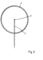
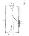
- the device shown in FIG. 1 for the continuous removal of samples from a particle-laden flow medium 9 flowing in a tube 1, in particular waste water, by means of a probe 2 protruding into the flow medium, the end 3 of which is directed downstream, requires a continuous suction of those for analysis purposes Liquid samples in a direction of 180 * - that is, opposite - to the flow direction 6 of the particle-laden flow medium in a region of laminar flow with the greatest flow velocity.
- the distribution of the flow velocities is indicated in FIG. 1 by arrows.
- FIG. 1 which is also illustrated by the sectional view “A” according to FIG. 2, makes it possible to extract a sample stream in a suction direction 7 opposite to the flow direction 6 of the main stream inside the tube 1.
- the design of the removal device according to the invention and the installation position described above advantageously have the effect that the removal device causes almost no turbulence in the suction area. Since the liquid samples are taken in the laminar region of the wastewater flow within the pipe 1, the effect of inertia can be fully exploited for the desired effect of cleaning the sample liquid and preventing possible blockages within the sampling device and / or the analysis devices.
- the sample liquid is sucked off by means of a suction drive 5, for example a pump, which is connected to the nozzle 1 of the first section of the tubular unit 2 which leads out of the fluid.
- a suction drive 5 for example a pump
- the aspirated particle-free sample liquid is then fed to an analysis device 4.
- This hose unit is also inserted at an angle of less than / equal to 45 through the wall of the tube 1 into the interior of the tube.
- the hose unit 12 Due to its elasticity, the hose unit 12 can easily be pulled into the area of the laminar flow in the pipe center by the flow in the pipe 1. There is also the highest flow rate, which guarantees the best degree of separation of the particles from the flow medium in the suction phase.
- the hose unit 12 is set into slight vibration by the flow in the tube 1 due to its elasticity.
- the vibration is strongest at the end free with the suction opening and thus prevents in the simplest way that particles from the flow medium can accumulate on the hose unit 12.
- FIGS. 4 and 5 Further advantageous variants of the solution according to the invention are shown in FIGS. 4 and 5.
- the tubular probe 2 is in the area of the pipe opening by means of an elastic one arranged in the area of the opening Bushing element 10 elastically supported.
- the tubular probe has two essentially straight sections 13, 14 which form an angle with one another, the first section 13 being arranged at an angle less than or equal to 45 to the wall of the tube carrying the particle-laden flow medium, and the second section 14 is directed parallel to the current direction.
- FIG. 5 shows a further exemplary embodiment, according to which the only second section of the tubular unit 2 is formed by an elastic piece of hose 11.
- the thin-walled tube piece 11 is preferably made of Teflon.
- the embodiment of the invention is not limited to the preferred exemplary embodiment specified above. Rather, a further number of variants is conceivable, which makes use of the solution shown, even in the case of different types.
Landscapes
- Life Sciences & Earth Sciences (AREA)
- Hydrology & Water Resources (AREA)
- Physics & Mathematics (AREA)
- Health & Medical Sciences (AREA)
- Chemical & Material Sciences (AREA)
- Analytical Chemistry (AREA)
- Biochemistry (AREA)
- General Health & Medical Sciences (AREA)
- General Physics & Mathematics (AREA)
- Immunology (AREA)
- Pathology (AREA)
- Sampling And Sample Adjustment (AREA)
- Automatic Analysis And Handling Materials Therefor (AREA)
Applications Claiming Priority (2)
| Application Number | Priority Date | Filing Date | Title |
|---|---|---|---|
| DE4032520 | 1990-10-11 | ||
| DE4032520A DE4032520A1 (de) | 1990-10-11 | 1990-10-11 | Vorrichtung zur entnahme von proben aus partikelbelasteten stroemungsmedien |
Publications (2)
| Publication Number | Publication Date |
|---|---|
| EP0481577A1 true EP0481577A1 (fr) | 1992-04-22 |
| EP0481577B1 EP0481577B1 (fr) | 1998-08-05 |
Family
ID=6416212
Family Applications (1)
| Application Number | Title | Priority Date | Filing Date |
|---|---|---|---|
| EP91250281A Expired - Lifetime EP0481577B1 (fr) | 1990-10-11 | 1991-10-11 | Dispositif pour le prélèvement continu des échantillons d'un milieu en écoulement chargé en particules |
Country Status (3)
| Country | Link |
|---|---|
| EP (1) | EP0481577B1 (fr) |
| AT (1) | ATE169404T1 (fr) |
| DE (2) | DE4032520A1 (fr) |
Cited By (3)
| Publication number | Priority date | Publication date | Assignee | Title |
|---|---|---|---|---|
| WO2006072382A1 (fr) * | 2005-01-07 | 2006-07-13 | Merck Patent Gmbh | Procede et dispositif de prelevement et d'analyse d'echantillons |
| DE102015102289A1 (de) | 2015-02-18 | 2016-08-18 | Endress + Hauser Conducta Gesellschaft für Mess- und Regeltechnik mbH + Co. KG | Vorrichtung zur Entnahme von Proben aus einer in einer Leitung fließenden Prozessflüssigkeit |
| WO2019109145A1 (fr) * | 2017-12-06 | 2019-06-13 | Alcoa Of Australia Limited | Dispositif d'échantillonnage de fluide |
Families Citing this family (4)
| Publication number | Priority date | Publication date | Assignee | Title |
|---|---|---|---|---|
| DE4214113C2 (de) * | 1992-04-29 | 1995-03-09 | Dohmen Karl J | Abwasserkanalschacht mit Einrichtungen zur Abwasserprobenentnahme oder/und zur Messung von Abwasserparametern |
| DE4316982C1 (de) * | 1993-05-21 | 1994-06-01 | Daimler Benz Ag | Vorrichtung für automatisiertes, selbsttätiges Probenehmen aus Abwasser zu dessen laufender Überwachung |
| DE4325793C2 (de) * | 1993-07-31 | 1997-07-17 | Integral Technologie Gmbh | Verfahren zur Messung einer Eiskonzentration und Vorrichtung zur Durchführung des Verfahrens |
| DE10011822A1 (de) * | 2000-03-10 | 2001-09-13 | Georg Haertel | Vorrichtung zur filterlosen On-Line Messung in Flüssigkeiten mittels Titrationsverfahren |
Citations (6)
| Publication number | Priority date | Publication date | Assignee | Title |
|---|---|---|---|---|
| GB917080A (en) * | 1960-09-14 | 1963-01-30 | Lord Mayor Aldermen Cit | Improvements in and relating to liquid samplers |
| US4481833A (en) * | 1982-12-27 | 1984-11-13 | Uop Inc. | Particle excluding sample probe |
| GB2154547A (en) * | 1984-02-24 | 1985-09-11 | George Levey | Liquid sampling device |
| AU577524B2 (en) * | 1983-04-05 | 1988-09-29 | Commonwealth Scientific And Industrial Research Organisation | Monitoring liquid streams containing solid debris |
| DE3724286A1 (de) * | 1987-07-22 | 1989-02-02 | Kajaani Electronics | Probenahmevorrichtung |
| US4941360A (en) * | 1989-06-14 | 1990-07-17 | Mcclellan Oliver B | Continuous (flexible) sewage monitoring machine for sampling building effluent to measure for certain controlled substances |
Family Cites Families (1)
| Publication number | Priority date | Publication date | Assignee | Title |
|---|---|---|---|---|
| US3921458A (en) * | 1974-03-01 | 1975-11-25 | Occidental Petroleum Corp | Isokinetic sampling probe |
-
1990
- 1990-10-11 DE DE4032520A patent/DE4032520A1/de not_active Withdrawn
-
1991
- 1991-10-11 AT AT91250281T patent/ATE169404T1/de not_active IP Right Cessation
- 1991-10-11 EP EP91250281A patent/EP0481577B1/fr not_active Expired - Lifetime
- 1991-10-11 DE DE59109037T patent/DE59109037D1/de not_active Expired - Fee Related
Patent Citations (6)
| Publication number | Priority date | Publication date | Assignee | Title |
|---|---|---|---|---|
| GB917080A (en) * | 1960-09-14 | 1963-01-30 | Lord Mayor Aldermen Cit | Improvements in and relating to liquid samplers |
| US4481833A (en) * | 1982-12-27 | 1984-11-13 | Uop Inc. | Particle excluding sample probe |
| AU577524B2 (en) * | 1983-04-05 | 1988-09-29 | Commonwealth Scientific And Industrial Research Organisation | Monitoring liquid streams containing solid debris |
| GB2154547A (en) * | 1984-02-24 | 1985-09-11 | George Levey | Liquid sampling device |
| DE3724286A1 (de) * | 1987-07-22 | 1989-02-02 | Kajaani Electronics | Probenahmevorrichtung |
| US4941360A (en) * | 1989-06-14 | 1990-07-17 | Mcclellan Oliver B | Continuous (flexible) sewage monitoring machine for sampling building effluent to measure for certain controlled substances |
Cited By (3)
| Publication number | Priority date | Publication date | Assignee | Title |
|---|---|---|---|---|
| WO2006072382A1 (fr) * | 2005-01-07 | 2006-07-13 | Merck Patent Gmbh | Procede et dispositif de prelevement et d'analyse d'echantillons |
| DE102015102289A1 (de) | 2015-02-18 | 2016-08-18 | Endress + Hauser Conducta Gesellschaft für Mess- und Regeltechnik mbH + Co. KG | Vorrichtung zur Entnahme von Proben aus einer in einer Leitung fließenden Prozessflüssigkeit |
| WO2019109145A1 (fr) * | 2017-12-06 | 2019-06-13 | Alcoa Of Australia Limited | Dispositif d'échantillonnage de fluide |
Also Published As
| Publication number | Publication date |
|---|---|
| EP0481577B1 (fr) | 1998-08-05 |
| DE4032520A1 (de) | 1992-04-16 |
| ATE169404T1 (de) | 1998-08-15 |
| DE59109037D1 (de) | 1998-09-10 |
Similar Documents
| Publication | Publication Date | Title |
|---|---|---|
| EP1062047B1 (fr) | Separateur cyclone | |
| DE3342016C2 (de) | Vorrichtung zum Mischen und Absetzen von partikelhaltigen Flüssigkeiten | |
| EP2864050B1 (fr) | Dispositif et procédé pour séparer des impuretés magnétisables de fluides en écoulement | |
| DE2551251B2 (de) | Verfahren zum Reinigen eines mit teilchenförmigen Verunreinigungen beladenen Gases | |
| EP0518221A1 (fr) | Séparateur de gouttelettes | |
| EP1034023A1 (fr) | Procede pour nettoyer des bougies d'un filtre a bougies | |
| EP0202356B2 (fr) | Dispositif de transport | |
| EP0309743B1 (fr) | Filtre à lavage à contre-courant | |
| EP0481577B1 (fr) | Dispositif pour le prélèvement continu des échantillons d'un milieu en écoulement chargé en particules | |
| DE3428428C2 (fr) | ||
| DE102009012444A1 (de) | Vorrichtung und Verfahren zum Filtern einer Flüssigkeit | |
| DE2146838B2 (de) | Verfahren und Vorrichtung zum Filtrieren von Flüssigkeiten | |
| EP1370847B1 (fr) | Sonde de mesure pour determiner en ligne la taille de particules en mouvement dans des substances transparentes | |
| WO1984002856A1 (fr) | Laveur de venturi pour gaz charges de poussieres | |
| EP0995479B1 (fr) | Dispositif et procédé pour l'adsorption, physique ou chimique, des composants d'un courant de gaz | |
| DE102010019873B4 (de) | Filtrationsvorrichtung | |
| DE3333898C2 (de) | Verfahren zum Reinigen von Abluft | |
| DE2917849C2 (de) | Abscheider für in einer Flüssigkeit schwebende Verunreinigungen von kleinerer Wichte als die der Flüssigkeit | |
| DE3826454A1 (de) | Vorrichtung zur abscheidung von verunreinigungen aus gas | |
| DE2058395A1 (de) | Siebvorrichtung zum Abscheiden von Feststoffen aus Fluessigkeitsstroemen in Rohrleitungen | |
| DE2801494C2 (de) | Verfahren zur Entspannungsflotation und Vorrichtung zur Durchführung des Verfahrens | |
| DE4407343A1 (de) | Vorrichtung zum Abscheiden von Partikeln mit fester Konsistenz aus einer Flüssigkeit | |
| DE2107908A1 (de) | Abscheider und Verfahren zum Ab scheiden von Flüssigkeit aus einem Gas Flussigkeits Gemisch | |
| DE19820259C2 (de) | Vorrichtung zum Reinigen, Spülen und Waschen eines Abwasserstromes in einem Zulaufgerinne einer Kläranlage | |
| DE2353484C3 (de) | Durchlauffilter zur Entnahme gefilterter Flüssigkeit aus einer verunreinigten Flüssigkeit |
Legal Events
| Date | Code | Title | Description |
|---|---|---|---|
| PUAI | Public reference made under article 153(3) epc to a published international application that has entered the european phase |
Free format text: ORIGINAL CODE: 0009012 |
|
| AK | Designated contracting states |
Kind code of ref document: A1 Designated state(s): AT BE CH DE FR GB IT LI NL |
|
| 17P | Request for examination filed |
Effective date: 19921021 |
|
| 17Q | First examination report despatched |
Effective date: 19941214 |
|
| GRAG | Despatch of communication of intention to grant |
Free format text: ORIGINAL CODE: EPIDOS AGRA |
|
| GRAG | Despatch of communication of intention to grant |
Free format text: ORIGINAL CODE: EPIDOS AGRA |
|
| GRAH | Despatch of communication of intention to grant a patent |
Free format text: ORIGINAL CODE: EPIDOS IGRA |
|
| GRAH | Despatch of communication of intention to grant a patent |
Free format text: ORIGINAL CODE: EPIDOS IGRA |
|
| GRAA | (expected) grant |
Free format text: ORIGINAL CODE: 0009210 |
|
| RAP1 | Party data changed (applicant data changed or rights of an application transferred) |
Owner name: LAR ANALYTIK UND UMWELTMESSTECHNIK GMBH |
|
| AK | Designated contracting states |
Kind code of ref document: B1 Designated state(s): AT BE CH DE FR GB IT LI NL |
|
| REF | Corresponds to: |
Ref document number: 169404 Country of ref document: AT Date of ref document: 19980815 Kind code of ref document: T |
|
| REG | Reference to a national code |
Ref country code: CH Ref legal event code: EP |
|
| REF | Corresponds to: |
Ref document number: 59109037 Country of ref document: DE Date of ref document: 19980910 |
|
| PG25 | Lapsed in a contracting state [announced via postgrant information from national office to epo] |
Ref country code: AT Free format text: LAPSE BECAUSE OF NON-PAYMENT OF DUE FEES Effective date: 19981011 |
|
| PGFP | Annual fee paid to national office [announced via postgrant information from national office to epo] |
Ref country code: BE Payment date: 19981022 Year of fee payment: 8 |
|
| PG25 | Lapsed in a contracting state [announced via postgrant information from national office to epo] |
Ref country code: LI Free format text: LAPSE BECAUSE OF NON-PAYMENT OF DUE FEES Effective date: 19981031 Ref country code: CH Free format text: LAPSE BECAUSE OF NON-PAYMENT OF DUE FEES Effective date: 19981031 |
|
| GBT | Gb: translation of ep patent filed (gb section 77(6)(a)/1977) |
Effective date: 19981109 |
|
| ET | Fr: translation filed | ||
| PLBE | No opposition filed within time limit |
Free format text: ORIGINAL CODE: 0009261 |
|
| STAA | Information on the status of an ep patent application or granted ep patent |
Free format text: STATUS: NO OPPOSITION FILED WITHIN TIME LIMIT |
|
| REG | Reference to a national code |
Ref country code: CH Ref legal event code: PL |
|
| 26N | No opposition filed | ||
| PG25 | Lapsed in a contracting state [announced via postgrant information from national office to epo] |
Ref country code: BE Free format text: LAPSE BECAUSE OF NON-PAYMENT OF DUE FEES Effective date: 19991031 |
|
| BERE | Be: lapsed |
Owner name: LAR ANALYTIK UND UMWELTMESSTECHNIK G.M.B.H. Effective date: 19991031 |
|
| REG | Reference to a national code |
Ref country code: GB Ref legal event code: IF02 |
|
| PGFP | Annual fee paid to national office [announced via postgrant information from national office to epo] |
Ref country code: GB Payment date: 20040928 Year of fee payment: 14 |
|
| PGFP | Annual fee paid to national office [announced via postgrant information from national office to epo] |
Ref country code: NL Payment date: 20041019 Year of fee payment: 14 Ref country code: FR Payment date: 20041019 Year of fee payment: 14 |
|
| PGFP | Annual fee paid to national office [announced via postgrant information from national office to epo] |
Ref country code: DE Payment date: 20041229 Year of fee payment: 14 |
|
| PG25 | Lapsed in a contracting state [announced via postgrant information from national office to epo] |
Ref country code: IT Free format text: LAPSE BECAUSE OF NON-PAYMENT OF DUE FEES;WARNING: LAPSES OF ITALIAN PATENTS WITH EFFECTIVE DATE BEFORE 2007 MAY HAVE OCCURRED AT ANY TIME BEFORE 2007. THE CORRECT EFFECTIVE DATE MAY BE DIFFERENT FROM THE ONE RECORDED. Effective date: 20051011 Ref country code: GB Free format text: LAPSE BECAUSE OF NON-PAYMENT OF DUE FEES Effective date: 20051011 |
|
| PG25 | Lapsed in a contracting state [announced via postgrant information from national office to epo] |
Ref country code: NL Free format text: LAPSE BECAUSE OF NON-PAYMENT OF DUE FEES Effective date: 20060501 |
|
| PG25 | Lapsed in a contracting state [announced via postgrant information from national office to epo] |
Ref country code: DE Free format text: LAPSE BECAUSE OF NON-PAYMENT OF DUE FEES Effective date: 20060503 |
|
| GBPC | Gb: european patent ceased through non-payment of renewal fee |
Effective date: 20051011 |
|
| PG25 | Lapsed in a contracting state [announced via postgrant information from national office to epo] |
Ref country code: FR Free format text: LAPSE BECAUSE OF NON-PAYMENT OF DUE FEES Effective date: 20060630 |
|
| NLV4 | Nl: lapsed or anulled due to non-payment of the annual fee |
Effective date: 20060501 |
|
| REG | Reference to a national code |
Ref country code: FR Ref legal event code: ST Effective date: 20060630 |