EP0481635A1 - Pointe et machine à faire les pointes - Google Patents
Pointe et machine à faire les pointes Download PDFInfo
- Publication number
- EP0481635A1 EP0481635A1 EP91309045A EP91309045A EP0481635A1 EP 0481635 A1 EP0481635 A1 EP 0481635A1 EP 91309045 A EP91309045 A EP 91309045A EP 91309045 A EP91309045 A EP 91309045A EP 0481635 A1 EP0481635 A1 EP 0481635A1
- Authority
- EP
- European Patent Office
- Prior art keywords
- head
- wire
- nail
- shank
- axis
- Prior art date
- Legal status (The legal status is an assumption and is not a legal conclusion. Google has not performed a legal analysis and makes no representation as to the accuracy of the status listed.)
- Granted
Links
- 230000001154 acute effect Effects 0.000 claims abstract description 15
- 239000002184 metal Substances 0.000 claims abstract description 15
- 239000000758 substrate Substances 0.000 claims description 13
- 230000007246 mechanism Effects 0.000 abstract description 7
- ORQBXQOJMQIAOY-UHFFFAOYSA-N nobelium Chemical compound [No] ORQBXQOJMQIAOY-UHFFFAOYSA-N 0.000 description 5
- 241000587161 Gomphocarpus Species 0.000 description 2
- 229910001315 Tool steel Inorganic materials 0.000 description 2
- 229910000975 Carbon steel Inorganic materials 0.000 description 1
- 239000010962 carbon steel Substances 0.000 description 1
- 238000004519 manufacturing process Methods 0.000 description 1
- 239000000463 material Substances 0.000 description 1
Images


Classifications
-
- F—MECHANICAL ENGINEERING; LIGHTING; HEATING; WEAPONS; BLASTING
- F16—ENGINEERING ELEMENTS AND UNITS; GENERAL MEASURES FOR PRODUCING AND MAINTAINING EFFECTIVE FUNCTIONING OF MACHINES OR INSTALLATIONS; THERMAL INSULATION IN GENERAL
- F16B—DEVICES FOR FASTENING OR SECURING CONSTRUCTIONAL ELEMENTS OR MACHINE PARTS TOGETHER, e.g. NAILS, BOLTS, CIRCLIPS, CLAMPS, CLIPS OR WEDGES; JOINTS OR JOINTING
- F16B15/00—Nails; Staples
- F16B15/02—Nails; Staples with specially-shaped heads, e.g. with enlarged surfaces
-
- F—MECHANICAL ENGINEERING; LIGHTING; HEATING; WEAPONS; BLASTING
- F16—ENGINEERING ELEMENTS AND UNITS; GENERAL MEASURES FOR PRODUCING AND MAINTAINING EFFECTIVE FUNCTIONING OF MACHINES OR INSTALLATIONS; THERMAL INSULATION IN GENERAL
- F16B—DEVICES FOR FASTENING OR SECURING CONSTRUCTIONAL ELEMENTS OR MACHINE PARTS TOGETHER, e.g. NAILS, BOLTS, CIRCLIPS, CLAMPS, CLIPS OR WEDGES; JOINTS OR JOINTING
- F16B15/00—Nails; Staples
- F16B15/08—Nails; Staples formed in integral series but easily separable
-
- Y—GENERAL TAGGING OF NEW TECHNOLOGICAL DEVELOPMENTS; GENERAL TAGGING OF CROSS-SECTIONAL TECHNOLOGIES SPANNING OVER SEVERAL SECTIONS OF THE IPC; TECHNICAL SUBJECTS COVERED BY FORMER USPC CROSS-REFERENCE ART COLLECTIONS [XRACs] AND DIGESTS
- Y10—TECHNICAL SUBJECTS COVERED BY FORMER USPC
- Y10S—TECHNICAL SUBJECTS COVERED BY FORMER USPC CROSS-REFERENCE ART COLLECTIONS [XRACs] AND DIGESTS
- Y10S411/00—Expanded, threaded, driven, headed, tool-deformed, or locked-threaded fastener
- Y10S411/923—Nail, spike or tack having specific head structure
Definitions
- This invention pertains to wire nails, as used in pneumatically powered nail-driving tools, and to strips of such nails, as collated by adhesively applied tapes or other collating media. Moreover, it pertains to machines as used to make such nails.
- wire nails having D-shaped or variant heads are collated by adhesively applied tapes or other collating media to form a strip.
- the shanks of the collated nails are oriented in closely spaced, parallel relation to one another and, except at one end of the strip, the head of each nail overlies the head of another nail.
- a wire nail having a head and a shank integral with the head, the shank being formed with a tip and having an axis, and the head having a circumferential edge defining a complete circle; is characterised in that the centre of the head is radially offset from the axis of the shank.
- a wire nail having a head and a shank integral with the head, the shank being formed with a tip and defining an axis and the head having a circumferential edge defining a complete circle and having an axis; is characterised in that the head has a lower portion defining a tangent plane, which is oriented normally to the axis of the head, and at an acute angle relative to the axis of the shank.
- a wire nail according to this invention may have structure providing a locating datum indicating where the shank is located after such nail has been driven into a substrate in such manner that the shank is concealed.
- the locating datum facilitates removal of the wire nail from the substrate, via a nail-prying tool having a forked tip, by indicating in what direction the forked tip can be effectively inserted beneath the head so that the nail-prying tool can apply substantially equal leverage to opposite sides of the head.
- a top portion of the head has two planar surfaces spaced from the shank, namely a first surface providing the datum and a second surface intersecting the first surface along a line extending across the head.
- the first surface is oriented at an obtuse, included angle (e.g. about 168°) relative to the second surface and the second surface is oriented at a right angle relative to the axis of the head.
- a lower portion of such a nail may have a cavity, which is bordered by an annular rib where the shank adjoins the head.
- the cavity tends to coact with a substrate, into which the nail is driven, so as to stabilize the nail head in a lateral sense.
- a lower portion of the head defines a tangent plane, which is oriented at a right angle relative to the axis of the head, and at an acute angle relative to the axis of the shank, preferably an acute angle in a range from about 75° to about 85°.
- the wire nail may have greater holding capability.
- the shank is formed with a keyway, which defines a flat surface providing an orienting datum for orienting such nail and similar nails with their shanks in parallel relation to one another and with their heads offset in a common direction.
- the flat surface of the keyway is parallel to the axis of the shank.
- such surface may conform to a parallelogram having two axially extending sides and two transversely extending sides, and such sides may define two acute angles and two obtuse angles.
- a strip of similar, collated, wire nails is made by adhesively applying tapes to the shanks of such nails for collating such nails, or by suitably applying other collating media thereto, to collate such nails with their shanks oriented in closely spaced, parallel relation to one another, and with their heads offset in a common direction relative to their shanks, so that the head of one such nail overlies the head of the next nail.
- the keyways noted above collectively define an open channel extending along the strip.
- the open channel may be advantageously used to guide the strip through a nail-feeding magazine having, on one wall, a lateral rib fitting into the open channel.
- a machine for making a nail from a wire of a malleable metal including means including two gripping elements for gripping the wire between the gripping elements in such manner that one end of the wire projects from the gripping elements, the wire defining an axis where gripped, is characterised by means for forming a head on the wire by deforming some of the malleable metal including the projecting end in such manner that the head has a circumferential edge in radially offset relation to the axis when the wire is viewed axially.
- each of the gripping elements has a recess where the projecting end projects.
- the recesses collectively define a cavity having an axis in radially offset relation to the axis defined by the wire where gripped.
- the nail head-forming mechanism includes a punch adapted to deform some of the malleable metal including the projecting end into a shape defined by the punch and by the cavity.
- the recess of each of the gripping elements may include an annular channel, whereupon the annular channels coact to define an annular rib on the malleable metal deformed by the punch into such shape.
- the punch has a cylindrical tip defining an axis and being movable axially into the cavity.
- One end of the cylindrical tip has two planar surfaces intersecting at a vee extending across the cylindrical tip, namely a first surface and a second surface.
- the first surface is oriented at an obtuse, included angle (e.g. about 168°) relative to the second surface and the second surface is oriented at a right angle relative to the axis of the punch.
- the first surface leads the second surface when the cylindrical tip is moved axially into the annular recess and is designed to deform some of the malleable metal including the projecting end laterally.
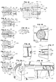
- a strip S of collated wire nails 10, each according to a preferred embodiment of this invention, is shown in Figures 1, 4, 5, and 6.
- the nail 10 has a unique head 12, by which the nail 10 is distinguished from wire nails known heretofore, and other unique features.
- the nail 10 has a shank 14 integral with the head 12.
- the shank 14 defines an axis and has a tip 16.
- the tip 16 conforms to the unique tip disclosed in Sygnator U.S. Patent No. 4,927,309, the disclosure of which is incorporated herein by reference.
- the shank 12 may have a conventional tip (not shown) having four facets.
- the head 12 has a circumferential edge 20 conforming to a complete circle and defining an axis in radially offset relation to the axis of the shank 14.
- the head 12 is radially offset in one direction relative to the shank 14.
- the head 12 defines a complete circle when viewed axially.
- the head 12 offers a better appearance when viewed axially.
- the head 12 may offer greater holding capability when the wire nail 10 is used to join two substrates, such as wooden boards.
- the head 12 at a top portion, has two planar surfaces spaced from the shank 14, namely a first surface 22 and a second surface 24.
- the second surface 24 intersects the first surface 22 along a crest 26, which extends across the head 12, which has a small radius (approximately 0.093 inch (2.4mm)) and which is shorter than a diameter of the complete circle defined by the circumferential edge 20 of the head 12.
- the first surface 22 is oriented at an obtuse, included angle of about 168° relative to the second surface 24 and the second surface 24 is oriented at a right angle relative to the axis of the shank 14.
- the first surface 22 provides an indicating datum indicating where the shank 14 is located after the wire nail 10 has been driven into a wooden board B or some other substrate (not shown) in such manner that the shank 14 is concealed.
- the datum provided by the first surface 22 facilitates removal of the wire nail 10 from the board B or other substrate, via a nail-prying tool having a forked tip T, by indicating in what direction the forked tip T can be effectively inserted beneath the head 12 so that the nail-prying tool can apply substantially equal leverage to opposite sides of the head 12.
- the shank 14 is formed with a keyway 28 defining a flat surface 30, which is parallel to the axis of the shank 14 and to the direction of radial offset of the head 12 relative to the shank 14, and which is spaced axially from the head 12.
- the flat surface 30 conforms to a parallelogram having two longer, axially extending sides 32, 34, and two shorter, transversely extending sides 36, 38. These longer and shorter sides define two acute angles (e.g. about 34° each) and two obtuse angles (e.g. about 146° each) as shown.
- the keyway 28 is bounded by two flat surfaces
- the flat surface 40 is bounded by the side 36 and by a curved edge 44 and is oriented at an angle of about 45° relative to the axis of the shank 14.
- the flat surface 42 is bounded by the side 38 and by a curved edge 46 and is oriented at an angle of about 45° relative to the axis of the shank 14 and at a right angle relative to the flat surface 40.
- the keyway 28 provides a datum for orienting the collated nails 10 with their shanks 14 in parallel relation to one another and with their heads 12 offset in a common direction relative to their shanks 14.
- the head 12 of the nail 10 has a cavity 50, which is bordered by an annular rib 52 except where the shank 14 adjoins the head 12.
- the head 12 tends to be less prone to separating from the shank 14, particularly if the head 12 is struck at a localized region spaced from the shank 14, e.g. where suggested by a wide arrow in Figure 2.
- the cavity 50 tends to coact with a substrate, into which the nail 10 is driven, so as to stabilize the nail head 12 in a lateral sense.
- the lower portion of the head 12 defines a tangent plane, which is oriented at a right angle relative to the axis of the head 12, and at a right angle relative to the shank 14.
- the preferred embodiment shown in Figures 1 through 6 and other views may be thus distinguished from an alternate embodiment shown in Figures 24 and 25, and from a simplified embodiment shown in Figure 26.
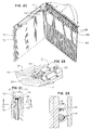
- the collated nails 10 of the strip S are collated via conventional collating tapes 62, 64, applied adhesively to opposite sides of the shanks 14 of the collated nails 10, in parallel relation to the flat surfaces 30 defined by the keyways 28 on the shanks 14 of the collated nails 10.
- the collating tapes 62, 64 are oriented at an acute angle (e.g. about 36°) relative to a plane normal to the axes of the shanks 14 of the collated nails 10 so as to be substantially parallel to the shorter sides 36, 38, of such flat surfaces 30.
- the nails 10 in the strip S are collated in such manner that their shanks 14 are oriented in closely spaced, parallel relation to one another, whereby their shanks 14 may be nearly contiguous to one another.
- the nails 10 in the strip S are collated in such manner that their heads 12 are offset in a common direction relative to their shanks 14 and in such manner that, except at one end of the strip S (its right end in Figure 4) where the nail 10 to be first or next driven is located, the head 12 of each nail 10 overlies the head 12 of another nail 10.
- the keyways 28 on the shanks 14 of the collated nails 10 define an open channel 66, which extends along the strip S .
- the open channel 66 is useful in guiding the strip S through a nail-feeding magazine 70 having two opposed walls 72, 74, and other structures (not shown) of known types to a pneumatically powered or combustion-powered nail-driving tool (not shown) of a known type.
- the wall 72 facing the keyways 28 has an integral, lateral rib 76 fitting into the open channel 66, whereby the rib 76 guides the strip S as the strip S is fed through the nail-feeding magazine 70.
- the wire nail 10 is formed from a wire of a malleable metal, such as carbon steel, which is preferred.
- the wire nail 10 can be effectively formed in a nail-making machine of a known type, such as a Wafios Model N51 Nail-Making Machine, as available commercially from Wafios Maschinenfabrik GmbH & Co. KG of Reutingen, Federal Republic of Germany.
- a nail-making machine employs coactive wire-gripping and head-forming mechanisms. It is contemplated by this invention that, in such a nail-making machine, improved wire-gripping and head-forming mechanisms are employed in a coactive combination.
- the wire-gripping mechanism comprises two gripping elements 100, 102, which are made from tool steel, and which are arranged for relative movement toward and away from each other.
- the gripping element 100 is stationary and the gripping element 102 is movable.
- the gripping elements 100, 102 are adapted to grip a wire W (from which the wire nail 10 is made) in such manner that one end W ' of the wire W projects from the gripping elements 100, 102.
- the gripping elements 100, 102 respectively have semi-cylindrical channels 104, 106, which are shaped to receive the wire W when the movable element 102 is moved into contiguous relation to the stationary element 100.
- the wire W defines an axis where gripped and the projecting end W ' projects axially.
- the gripping elements 100, 102 respectively have recesses 110, 112, where the projecting end W' of the wire W projects.
- the recess 110 communicates with the semi-cylindrical channel 104.
- the recess 112 communicates with the semi-cylindrical channel 106.
- the recesses 110, 112 coact to define a cavity, which has an axis in radially offset relation to the axis defined by the wire W where gripped.
- the recess 110 includes an annular channel 114.
- the recess 112 includes an annular channel 116.
- the annular channels 114, 116 correspond to the annular rib 52 of the head 12 of the nail 10 being made.
- the semi-cylindrical channel 106 of the movable element 102 is interrupted by a nub 120, which is integral with the movable element 102, and which is shaped to form the flat surface 30 and the flat surfaces 40, 42, along a portion of the wire W to become the shank 14 of the wire nail 10 being made.
- the nub 120 forms these surfaces by deforming some of the malleable material of the wire W , as the movable element 102 is moved into contiguous relation to the stationary element 100.
- the nub 120 has a flat surface 122 corresponding to the flat surface 30, a flat surface 124 corresponding to the flat surface 40, and a flat surface 126 corresponding to the flat surface 42.
- the head-forming mechanism comprises a punch 130, which is made from tool steel, and which is adapted to deform some of the malleable metal including the projecting end W ' of the wire W into a shape defined by the punch 130 and by the cavity defined by the recesses 110, 112, namely into the shape of the head 12 of the wire nail 10 being made.
- the punch 130 has a cylindrical tip 132, which defines an axis, and which conforms closely to the cavity defined by the recesses 110, 112, and which is movable axially into such cavity.
- the end of the cylindrical tip 132 has two planar surfaces, namely a first surface 134 and a second surface 136 intersecting the first surface 134 at a vee 138 extending across the cylindrical tip 132.
- the vee 138 has a slight radius (e.g. approximately 0.093 inch 2.4mm) and is shorter than a diameter of the cylindrical tip 132.
- the first surface 134 is oriented at an obtuse, included angle of about 168° relative to the second surface 136 and the second surface 136 is oriented at a right angle relative to the axis of the punch 130.
- the first surface 134 leads the second surface 136 and is designed to deform some of the malleable metal including the projecting end W ' of the wire W laterally, whereby the deformed metal fills inner reaches of the cavity defined by the recesses 110, 112.
- the first surface 22 of the head 12 conforms closely to the first surface 134 of the end of the cylindrical tip 132 of the punch 130.
- the second surface 24 of the head 12 conforms closely to the second surface 136 of the end of the cylindrical tip 132 of the punch 130.
- the annular rib 52 of the head 12 conforms closely to the annular channels 114, 116.
- a wire nail 10' according to the alternate embodiment of this invention has a head 12', which conforms to the head 12 of the wire nail 10.
- the wire nail 10' has a shank 14', which is similar to the shank 14 of the wire nail 10 except as explained herein.
- the shank 14' has a keyway 28' with flat surfaces 30', 40', 42', which correspond respectively to the keyway 28 with flat surfaces 30, 40, 42, on the shank 14 of the wire nail 10.
- the shank 14' is formed with a tip 16', which conforms to the tip 16 of the wire nail 10 and to the unique tip disclosed in the Sygnator patent noted above.
- the head 12' of the wire nail 10' defines a tangent plane, which is oriented at a right angle relative to the axis of the head 12', but at an acute angle relative to the axis of the shank 14'.
- the acute angle is in a range from about 75° to about 85°.
- the wire nail 10' may have greater holding capability when driven through an upper substrate B 1, such as a wooden board, into a lower substrate B 2, such as a wooden board.
- a wire nail 10" according to a simplified embodiment of this invention is shown in Figure 26, as driven through an upper substrate B 1, such as a wooden board, into a lower substrate B 2, such as a wooden board.
- double-primed reference numbers are used to designate elements similar or analogous to elements designated by similar, unprimed reference numbers in Figures 1 through 6 and other views.
- the wire nail 10'' has a head 12'', which defines an axis, and a shank 14'', which defines an axis, and which is joined integrally with the head 12''.
- the head 12'' is similar to the heads of wire nails (not shown) in common use.
- the shank 14'' is similar to the shanks of such nails.
- the wire nail 10'' has a tip (not shown) similar to the tips of such nails.
- the wire nail 10'' is similar to the wire nail 10' described above and differs from wire nails in common use in that, at a lower portion, the head 12'' defines a tangent plane, which is oriented at a right angle relative to the axis of the head 12'', but at an acute angle relative to the axis of the shank 14''.
Landscapes
- Engineering & Computer Science (AREA)
- General Engineering & Computer Science (AREA)
- Mechanical Engineering (AREA)
- Portable Nailing Machines And Staplers (AREA)
Applications Claiming Priority (2)
| Application Number | Priority Date | Filing Date | Title |
|---|---|---|---|
| US07/597,025 US5056976A (en) | 1990-10-15 | 1990-10-15 | Wire nail, strip of collated wire nails, and related apparatus |
| US597025 | 1990-10-15 |
Publications (2)
| Publication Number | Publication Date |
|---|---|
| EP0481635A1 true EP0481635A1 (fr) | 1992-04-22 |
| EP0481635B1 EP0481635B1 (fr) | 1994-12-14 |
Family
ID=24389759
Family Applications (1)
| Application Number | Title | Priority Date | Filing Date |
|---|---|---|---|
| EP91309045A Expired - Lifetime EP0481635B1 (fr) | 1990-10-15 | 1991-10-02 | Pointe et machine à faire les pointes |
Country Status (9)
| Country | Link |
|---|---|
| US (1) | US5056976A (fr) |
| EP (1) | EP0481635B1 (fr) |
| JP (1) | JP3358823B2 (fr) |
| AU (1) | AU650907B2 (fr) |
| CA (1) | CA2049566C (fr) |
| DE (1) | DE69105909T2 (fr) |
| HK (1) | HK128295A (fr) |
| NZ (1) | NZ239681A (fr) |
| SG (1) | SG28379G (fr) |
Cited By (1)
| Publication number | Priority date | Publication date | Assignee | Title |
|---|---|---|---|---|
| US7014407B2 (en) | 2002-05-23 | 2006-03-21 | Stanley Fastening Systems, L.P. | Full-round, offset-head nail |
Families Citing this family (14)
| Publication number | Priority date | Publication date | Assignee | Title |
|---|---|---|---|---|
| US5395197A (en) * | 1994-02-25 | 1995-03-07 | Cario; Antonio | Nail with non-circular head |
| US5482419A (en) * | 1994-07-27 | 1996-01-09 | Leistner; Herbert E. | Nail with offset reinforced head |
| US6010291A (en) * | 1999-01-29 | 2000-01-04 | Schwingle; Shawn L. | Collatable cap nail |
| USD429628S (en) * | 1999-11-05 | 2000-08-22 | The Fletcher-Terry Company | Nail |
| US7395925B2 (en) * | 2002-02-01 | 2008-07-08 | Stanley Fastening Systems, L.P. | Pallet nail with enlarged head |
| US6758018B2 (en) | 2002-02-01 | 2004-07-06 | Stanley Fastening Systems, L.P. | Power driven nails for sheathing having enlarged diameter heads for enhanced retention and method |
| US6926485B1 (en) * | 2004-01-23 | 2005-08-09 | Chun Fu Wu | Nail heads of a nail row |
| US20060070313A1 (en) * | 2004-10-02 | 2006-04-06 | Moblo Glenn R | Self-leveling form stake |
| US7618222B2 (en) * | 2006-03-01 | 2009-11-17 | Chi Hyun Kim | Collated fastener strips with opposing wire connectors |
| US7845888B2 (en) * | 2006-04-11 | 2010-12-07 | Illinois Tool Works Inc. | Scalloped tape collating strip for nails |
| US8920094B2 (en) * | 2008-07-18 | 2014-12-30 | Illinois Tool Works Inc. | Apparatus and method of making an offset nail |
| US8100618B2 (en) * | 2008-07-18 | 2012-01-24 | Illinois Tool Works Inc. | Apparatus and method of making a heel-less nail |
| CA3153933A1 (fr) * | 2019-09-10 | 2021-03-18 | Pneutools, Inc. | Outil a agrafer directionnel et clous |
| US12146517B2 (en) * | 2020-04-30 | 2024-11-19 | Altenloh, Brinck & Co. Us, Inc. | Self-sealing fastener |
Citations (11)
| Publication number | Priority date | Publication date | Assignee | Title |
|---|---|---|---|---|
| US2940081A (en) | 1959-06-10 | 1960-06-14 | Senco Products | Cohered, full headed nail |
| US3152334A (en) | 1963-07-30 | 1964-10-13 | Signode Steel Strapping Co | Nails |
| US3359582A (en) | 1965-11-22 | 1967-12-26 | Bethlehem Steel Corp | Die assembly for making chamfer headed nails |
| US3481459A (en) | 1968-04-19 | 1969-12-02 | Senco Products | Nails in strip form |
| DE2319374A1 (de) * | 1972-09-15 | 1974-04-04 | Senco Products | Nagel sowie verfahren und vorrichtung zu dessen herstellung |
| US3861526A (en) | 1972-10-20 | 1975-01-21 | Walter Hermann Leistner | Nail strip and nail shaped for arrangement in strip |
| US3966042A (en) | 1973-04-25 | 1976-06-29 | Signode Corporation | Fastener strip |
| DE2748862A1 (de) | 1977-10-31 | 1979-05-10 | Dieter Haubold Ind Nagelgeraet | Nagelstreifen |
| DD142302A5 (de) * | 1979-03-08 | 1980-06-18 | Nordiske Kabel Traad | Maschine zum formen von koepfen an schaeften |
| US4927309A (en) | 1989-05-08 | 1990-05-22 | Sygnator Henry A | Wire nail |
| EP0481636A1 (fr) | 1990-10-15 | 1992-04-22 | Illinois Tool Works Inc. | Machine et procédé pour assembler des clous ayant des tiges présentant des cavités de guidage |
Family Cites Families (3)
| Publication number | Priority date | Publication date | Assignee | Title |
|---|---|---|---|---|
| US3358822A (en) * | 1967-03-06 | 1967-12-19 | Textron Inc | Fastener stick embodying nails with eccentric full round heads |
| US3861527A (en) * | 1972-12-04 | 1975-01-21 | Spotnails | Package of collated fasteners |
| US3935945A (en) * | 1975-04-09 | 1976-02-03 | Textron, Inc. | Open sided partially circular headed nail with recess along the open-sided edge thereof and stick package formed therefrom |
-
1990
- 1990-10-15 US US07/597,025 patent/US5056976A/en not_active Expired - Lifetime
-
1991
- 1991-08-20 CA CA002049566A patent/CA2049566C/fr not_active Expired - Lifetime
- 1991-09-05 NZ NZ239681A patent/NZ239681A/en not_active IP Right Cessation
- 1991-10-02 DE DE69105909T patent/DE69105909T2/de not_active Expired - Lifetime
- 1991-10-02 EP EP91309045A patent/EP0481635B1/fr not_active Expired - Lifetime
- 1991-10-02 SG SG1995905964A patent/SG28379G/en unknown
- 1991-10-07 JP JP28544891A patent/JP3358823B2/ja not_active Expired - Lifetime
- 1991-10-10 AU AU85715/91A patent/AU650907B2/en not_active Expired
-
1995
- 1995-08-10 HK HK128295A patent/HK128295A/en not_active IP Right Cessation
Patent Citations (11)
| Publication number | Priority date | Publication date | Assignee | Title |
|---|---|---|---|---|
| US2940081A (en) | 1959-06-10 | 1960-06-14 | Senco Products | Cohered, full headed nail |
| US3152334A (en) | 1963-07-30 | 1964-10-13 | Signode Steel Strapping Co | Nails |
| US3359582A (en) | 1965-11-22 | 1967-12-26 | Bethlehem Steel Corp | Die assembly for making chamfer headed nails |
| US3481459A (en) | 1968-04-19 | 1969-12-02 | Senco Products | Nails in strip form |
| DE2319374A1 (de) * | 1972-09-15 | 1974-04-04 | Senco Products | Nagel sowie verfahren und vorrichtung zu dessen herstellung |
| US3861526A (en) | 1972-10-20 | 1975-01-21 | Walter Hermann Leistner | Nail strip and nail shaped for arrangement in strip |
| US3966042A (en) | 1973-04-25 | 1976-06-29 | Signode Corporation | Fastener strip |
| DE2748862A1 (de) | 1977-10-31 | 1979-05-10 | Dieter Haubold Ind Nagelgeraet | Nagelstreifen |
| DD142302A5 (de) * | 1979-03-08 | 1980-06-18 | Nordiske Kabel Traad | Maschine zum formen von koepfen an schaeften |
| US4927309A (en) | 1989-05-08 | 1990-05-22 | Sygnator Henry A | Wire nail |
| EP0481636A1 (fr) | 1990-10-15 | 1992-04-22 | Illinois Tool Works Inc. | Machine et procédé pour assembler des clous ayant des tiges présentant des cavités de guidage |
Cited By (2)
| Publication number | Priority date | Publication date | Assignee | Title |
|---|---|---|---|---|
| US7014407B2 (en) | 2002-05-23 | 2006-03-21 | Stanley Fastening Systems, L.P. | Full-round, offset-head nail |
| US7374383B2 (en) | 2002-05-23 | 2008-05-20 | Stanley Fastening Systems, L.P. | Full-round, offset-head nail |
Also Published As
| Publication number | Publication date |
|---|---|
| JP3358823B2 (ja) | 2002-12-24 |
| CA2049566A1 (fr) | 1992-04-16 |
| CA2049566C (fr) | 1996-01-09 |
| DE69105909T2 (de) | 1995-07-20 |
| NZ239681A (en) | 1994-05-26 |
| SG28379G (en) | 1995-09-01 |
| DE69105909D1 (de) | 1995-01-26 |
| HK128295A (en) | 1995-08-18 |
| EP0481635B1 (fr) | 1994-12-14 |
| AU650907B2 (en) | 1994-07-07 |
| US5056976A (en) | 1991-10-15 |
| JPH0610925A (ja) | 1994-01-21 |
| AU8571591A (en) | 1992-04-16 |
Similar Documents
| Publication | Publication Date | Title |
|---|---|---|
| EP0481635B1 (fr) | Pointe et machine à faire les pointes | |
| EP0367936B1 (fr) | Bande de clous | |
| US5443345A (en) | Fastener-sleeve assembly and strip of collated fasteners | |
| US5154670A (en) | Apparatus for forming a wire nail | |
| US4002098A (en) | Notched head nail having a pair of depending annularly spaced radial abutment ribs and package thereof | |
| US5971688A (en) | Fastener for laminate flooring | |
| US3935945A (en) | Open sided partially circular headed nail with recess along the open-sided edge thereof and stick package formed therefrom | |
| AU709205B2 (en) | Angled chisel point brad and method therefor | |
| US5482419A (en) | Nail with offset reinforced head | |
| CA2049565C (fr) | Clous en bande avec meplat d'assemblage | |
| US5615985A (en) | Collated fastener strip | |
| US4877135A (en) | Collated nail strip | |
| EP0042657A1 (fr) | Clous | |
| US7014407B2 (en) | Full-round, offset-head nail | |
| US5395197A (en) | Nail with non-circular head | |
| WO1997042421A1 (fr) | Clou et bande de clous destines a etre utilises avec un outil mecanique d'entrainement de fixation | |
| US5533379A (en) | Method of forming a head on a fastener | |
| MXPA98005131A (en) | Lost head nail with inclined chisel edge and method for e | |
| GB2136906A (en) | Strip collatable nails | |
| AU2003231663A1 (en) | Improvements in D-head and notched D-head nails |
Legal Events
| Date | Code | Title | Description |
|---|---|---|---|
| PUAI | Public reference made under article 153(3) epc to a published international application that has entered the european phase |
Free format text: ORIGINAL CODE: 0009012 |
|
| AK | Designated contracting states |
Kind code of ref document: A1 Designated state(s): DE FR GB SE |
|
| 17P | Request for examination filed |
Effective date: 19920924 |
|
| 17Q | First examination report despatched |
Effective date: 19930909 |
|
| GRAA | (expected) grant |
Free format text: ORIGINAL CODE: 0009210 |
|
| AK | Designated contracting states |
Kind code of ref document: B1 Designated state(s): DE FR GB SE |
|
| REF | Corresponds to: |
Ref document number: 69105909 Country of ref document: DE Date of ref document: 19950126 |
|
| EAL | Se: european patent in force in sweden |
Ref document number: 91309045.2 |
|
| ET | Fr: translation filed | ||
| PLBE | No opposition filed within time limit |
Free format text: ORIGINAL CODE: 0009261 |
|
| STAA | Information on the status of an ep patent application or granted ep patent |
Free format text: STATUS: NO OPPOSITION FILED WITHIN TIME LIMIT |
|
| 26N | No opposition filed | ||
| REG | Reference to a national code |
Ref country code: GB Ref legal event code: IF02 |
|
| PGFP | Annual fee paid to national office [announced via postgrant information from national office to epo] |
Ref country code: SE Payment date: 20091028 Year of fee payment: 19 Ref country code: DE Payment date: 20091028 Year of fee payment: 19 |
|
| PGFP | Annual fee paid to national office [announced via postgrant information from national office to epo] |
Ref country code: GB Payment date: 20091026 Year of fee payment: 19 Ref country code: FR Payment date: 20091029 Year of fee payment: 19 |
|
| GBPC | Gb: european patent ceased through non-payment of renewal fee |
Effective date: 20101002 |
|
| PG25 | Lapsed in a contracting state [announced via postgrant information from national office to epo] |
Ref country code: FR Free format text: LAPSE BECAUSE OF NON-PAYMENT OF DUE FEES Effective date: 20101102 |
|
| REG | Reference to a national code |
Ref country code: FR Ref legal event code: ST Effective date: 20110630 |
|
| REG | Reference to a national code |
Ref country code: DE Ref legal event code: R119 Ref document number: 69105909 Country of ref document: DE Effective date: 20110502 |
|
| PG25 | Lapsed in a contracting state [announced via postgrant information from national office to epo] |
Ref country code: GB Free format text: LAPSE BECAUSE OF NON-PAYMENT OF DUE FEES Effective date: 20101002 |
|
| PG25 | Lapsed in a contracting state [announced via postgrant information from national office to epo] |
Ref country code: SE Free format text: LAPSE BECAUSE OF NON-PAYMENT OF DUE FEES Effective date: 20101003 |
|
| PG25 | Lapsed in a contracting state [announced via postgrant information from national office to epo] |
Ref country code: DE Free format text: LAPSE BECAUSE OF NON-PAYMENT OF DUE FEES Effective date: 20110502 |