EP0481639B1 - Enrouleuse - Google Patents
Enrouleuse Download PDFInfo
- Publication number
- EP0481639B1 EP0481639B1 EP91309117A EP91309117A EP0481639B1 EP 0481639 B1 EP0481639 B1 EP 0481639B1 EP 91309117 A EP91309117 A EP 91309117A EP 91309117 A EP91309117 A EP 91309117A EP 0481639 B1 EP0481639 B1 EP 0481639B1
- Authority
- EP
- European Patent Office
- Prior art keywords
- winding
- yarn
- operating position
- winding machine
- empty tube
- Prior art date
- Legal status (The legal status is an assumption and is not a legal conclusion. Google has not performed a legal analysis and makes no representation as to the accuracy of the status listed.)
- Expired - Lifetime
Links
- 238000004804 winding Methods 0.000 title claims description 54
- 230000003213 activating effect Effects 0.000 claims description 2
- 239000002699 waste material Substances 0.000 description 2
- 230000004913 activation Effects 0.000 description 1
- 238000007664 blowing Methods 0.000 description 1
- 230000000977 initiatory effect Effects 0.000 description 1
Images

Classifications
-
- B—PERFORMING OPERATIONS; TRANSPORTING
- B65—CONVEYING; PACKING; STORING; HANDLING THIN OR FILAMENTARY MATERIAL
- B65H—HANDLING THIN OR FILAMENTARY MATERIAL, e.g. SHEETS, WEBS, CABLES
- B65H65/00—Securing material to cores or formers
-
- B—PERFORMING OPERATIONS; TRANSPORTING
- B65—CONVEYING; PACKING; STORING; HANDLING THIN OR FILAMENTARY MATERIAL
- B65H—HANDLING THIN OR FILAMENTARY MATERIAL, e.g. SHEETS, WEBS, CABLES
- B65H2701/00—Handled material; Storage means
- B65H2701/30—Handled filamentary material
- B65H2701/31—Textiles threads or artificial strands of filaments
Definitions
- This invention relates a winding machine according to the preamble of claim 1.
- Conventional spindle driven winding machines are provided with one of several known arrangements for effecting such transfer. Such arrangements involve the provision of grooves or other special features on the surface of the empty tube, or teeth, slots or the like on the tube gripping chuck of the winding machine. These "yarn-catcher” features are provided so that, after the yarn travelling to the full package has been cut, the free end of the incoming yarn can be guided in the vicinity of the "yarn-catcher” feature to be gripped thereby and winding of the yarn onto the empty tube can be commenced.
- the invention provides a winding machine according to claim 1.
- the guide means may comprise a pair of curved plates, and the plates may have a radius of curvature substantially equal to that of the periphery of an empty tube.
- the plates When in the operating position, the plates may be disposed on opposed sides of the empty tube to substantially surround its periphery, with adjacent edges of the plates spaced from each other to define the entry and exit apertures therebetween.
- the plates When in the non-operating position, the plates may be disposed on opposed sides of the winding position and spaced from each other by a distance greater than the diameter of a fully wound package.
- the cutter means may be in the path of the yarn from the exit aperture.
- the cutter means may be mounted on one of the plates at an edge thereof which defines the exit aperture when the plates are in the operating position.
- the winding machine may be a spindle driven winding machine, and may comprise a turret on which two spindles are mounted.
- the turret may be rotatable in the machine whereby an 180° rotation of the turret causes the positions of the two spindles to be exchanged between the winding position and a doffing position.
- the winding machine may also comprise a bale roller disposed to contact the periphery of an empty tube when in the winding position, and movable in the machine so as to remain in contact with the periphery of a package being wound on a tube in the winding position.
- the winding machine may comprise control means operable when the bale roller reaches a predetermined location, corresponding with a package being fully wound, to rotate the turret to move the fully wound package from the winding position to the doffing position, and an empty tube from the doffing position to the winding position, and then to move the guide means from the non-operating position to the operating position.
- the control means may be operable to activate the cutter means when the guide means is in the operating position, and may also be operable a predetermined time interval after activating the cutter means, to move the guide means back from the operating position to the non-operating position.
- the winding machine may also comprise traverse means and deflecting means, in which case the control means may be operable to move the deflecting means so as to disengage the yarn from the traverse means after rotating the turret but before operating the cutter, and to retract the deflecting means so as to allow re-engagement of the yarn by the traverse means after the guide means has been moved back from the operating position to the non-operating position.
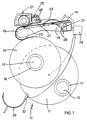
- a winding machine 10 having a turret 11 mounted therein and two spindles 12, 13 mounted on the turret 11.
- a yarn 14 is being wound into a package 15 on a tube 16 secured on the spindle 13, which is in the winding position.
- An empty tube 17 is secured on the spindle 12, which is in the doffing position.
- the winding machine 10 has driving means (not shown) for driving the spindles 12,13 in rotation, and hence the tubes 16, 17 and any package 15 on a tube 16.
- the yarn 14 is laid on the surface of the tube 17 or package 15 by means of bale roller 18, which is freely rotatably mounted on an arm 19.
- the yarn 14 Prior to passing around the bale roller 18, the yarn 14 is guided by a traversing yarn guide 20 of a traverse mechanism 21.
- the traverse mechanism 21 and the arm 19 are arranged to pivot together in the machine 10 about a pivot axis 22, so that the bale roller 18 can move upwardly as the diameter of the package 15 increases during winding, together with the arm 19 and the traverse mechanism 21.
- the arm 19 contacts a sensor 23 which sends a signal to control means 24.
- the control means 24 initiates the transfer operation by causing rotation of the turret 11 so that the spindle 13, tube 16 and package 15 move from the winding position to the doffing position, and the spindle 12 and empty tube 17 move from the doffing position to the winding position.
- the control means 24 then causes activation of a pneumatic cylinder 25 of the traverse mechanism 21.
- the extension of cylinder 25 causes movement of a swinging arm 26 and a deflecting means 27, in the form of a lift off plate, to disengage the yarn 14 from the traverse guide 20.
- the yarn 14 is wound onto the package 15 at a single location axially thereof, which may be arranged to be a mid position or at either end of the package 15 as desired.
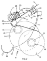
- the machine 10 is then in the condition illustrated in Fig 2.
- the bale roller 18 is in contact with and is driven by the empty tube 17 and the yarn 14 travels a small distance around the periphery of the empty tube 17 before passing to the package 15.
- such contact between the yarn 14 and the tube 17 would be insufficient to entrain the yarn 14 to be wound onto the tube 17 if the yarn 14 were to be cut in the region between the empty tube 17 and the package 15.
- control means 24 initiates movement of upper guide means 28 and lower guide means 29 from a non-operating position as shown in Figs 1 and 2, to an operating position as shown in Fig 3.
- the guide means 28,29 are disposed spaced apart on opposed sides of the winding position by a distance greater than the diameter of a fully wound package 15, and sufficient to enable rotation of the turret 11 without contact between the package 15 and upper guide 28, or tube 17 and lower guide 29.
- the upper guide 28 and the lower guide 29 are disposed so as to substantially surround the periphery of the empty tube 17, with only a small clearance between the guides 28, 29 and the tube 17.
- the adjacent edges of the guides 28, 29 define an entry aperture 30 for the yarn 14 to pass from the bale roller 18 to the tube 17, and an exit aperture 31, for the yarn 14 to pass from the tube 17 to the package 15.
- a yarn cutter 32 is mounted on the lower guide 29 adjacent the edge thereof which defines the exit aperture 31 so that the yarn 14 is caused to pass through the cutter 32 as it leaves the exit aperture 31.
- the control means 24 then activates the cutter 32.
- the package 15 is thereby detached from the supply of yarn 14, so that the spindle 13 can be stopped and the package 15 doffed therefrom. A new empty tube can then be placed on the spindle 13 and the drive thereto recommenced.
- the upper guide 28 deflects the yarn 14 further around the periphery of the empty tube 17 than was the case previously as illustrated in Fig 2.
- the free end drops between the tube 17 and the lower guide 29 so as to be carried around the periphery of the tube 17.
- the free end of the yarn 14 reaches the region of the entry aperture 30 it is gripped in the nip between the bale roller 18 and the tube 17 so that a second lap of yarn 14 is formed on the tube 17. Since the yarn 14 is out of contact with the traverse guide 20, the incoming yarn 14 tends to lie on top of and trap previous laps of yarn 14 wound on the tube 17, so that after a very few laps the yarn 14 is securely held onto the tube 17.
- the control means 24 then causes the guide means 28, 29 to retract to the non-operating position, and the pneumatic cylinder 25 to retract also so that the traverse guide 20 again engages the yarn 14.
- Winding of a package on the tube 17 then proceeds normally until the condition illustrated in Fig 1 is reached, whereupon the transfer operation is repeated.
- the arrangement may be applied to a swinging arm winding machine instead of a rotating turret type of machine.
- the initiation of the transfer operation may be by means of a timing or yarn length measuring device, or package size or weight sensor, instead of an arm position sensor as described herein.
- Movement of the guide means may be by means of linear motors, hydraulic or pneumatic means as desired.
- the bale roller and traverse mechanism may move linearly towards and away from the winding position instead of being mounted for pivotal movement as described herein.
- the upper and/or lower guide means may be mounted for pivotal movement between their non-operating and operating positions, instead of performing linear movements as shown in the Figures.
Landscapes
- Replacing, Conveying, And Pick-Finding For Filamentary Materials (AREA)
- Spinning Or Twisting Of Yarns (AREA)
Claims (10)
- Machine de bobinage (10) comprenant une position de bobinage dans laquelle un tube vide (17) peut être déplacé, et un dispositif de transfert de fil comprenant des moyens de guidage (28, 29) mobiles, lorsqu'un tube vide (17) s'est déplacé vers la position de bobinage, d'une position de repos située loin de la position de bobinage, à une position de marche caractérisée en ce que, dans la position de marche, les moyens de guidage (28, 29) entourant essentiellement le tube vide (17) et sont prêts à guider un fil défilant. (14) autour de la périphérie du tube vide (17), les moyens de guidage (28, 29) possédant une ouverture d'entrée (30) par laquelle le fil (14) peut se déplacer jusqu'à la périphérie du tube vide (17), et, opposée au niveau de la circonférence, une ouverture de sortie (31) par laquelle le fil (14) peut passer en provenant de la périphérie du tube vide (17), et un moyen formant lame (32) placé sur le trajet du fil (14), adjacent à l'ouverture de sortie (31).
- Machine de bobinage (10) suivant la revendication 1, caractérisée en ce que les moyens de guidage (28, 29) comprennent une paire de plaques courbes (28, 29) dont le rayon de courbure est essentiellement égal à celui de la périphérie d'un tube vide (17).
- Machine de bobinage (10) suivant la revendication 2, caractérisée en ce que les plaques (28, 29), lorsqu'elles sont en position de marche, sont placées sur des côtés opposés du tube vide (17) pour entourer essentiellement sa périphérie, les bords adjacents des plaques (28, 29) étant espacés l'un de l'autre pour définir les ouvertures d'entrée (30) et de sortie (31) entre elles.
- Machine de bobinage (10) suivant la revendication 2 ou la revendication 3 caractérisée en ce que les plaques (28, 29), lorsqu'elles sont en position de repos, sont placées sur des côtés opposés de la position de bobinage et espacées l'une de l'autre par une distance supérieure au diamètre d'une bobine complètement enroulée.
- Machine de bobinage (10) suivant les revendications 2 à 4, caractérisée en ce que le moyen formant lame (32) est monté sur l'une des plaques (29) sur un de leurs côtés qui définit l'ouverture de sortie (31) lorsque les plaques (28, 29) sont en position de marche.
- Machine de bobinage (10) suivant l'une des revendications 1 à 5, dans laquelle la machine de bobinage est une machine de bobinage commandée par une broche caractérisée en ce qu'elle comprend une tourelle (11) sur laquelle sont montées deux broches (12, 13), et en ce que la tourelle (11) est mobile autour d'un axe dans la machine (10) au moyen de laquelle une rotation de 180° de la tourelle (11) fait que les positions des deux broches (12, 13) deviennent la position de bobinage et une position de décharge.
- Machine de bobinage (10) suivant la revendication 6, caractérisée en ce qu'elle comprend un rouleau de balle (18) disposé de façon à être en contact avec la périphérie du tube vide (17) lorsqu'elle est en position de bobinage, et mobile dans la machine (10) de façon à rester en contact avec la périphérie d'une bobine (15) enroulée sur un tube (16) en position de bobinage, et un moyen de commande (24) fonctionnant lorsque le rouleau de balle (18) atteint un emplacement prédéterminé, correspondant à une bobine (15) complètement enroulée, pour faire tourner la tourelle (11) afin de déplacer la bobine complètement enroulée (15) de la position de bobinage à la position de décharge, et un tube vide (17) de la position de décharge à la position de bobinage, et ensuite de déplacer les moyens de guidage (28, 29) de la position de repos à la position de marche.
- Machine de bobinage suivant la revendication 7, caractérisée en ce que le moyen de commande (24) est prêt à activer le moyen formant lame (32) lorsque les moyens de guidage (28, 29) sont en position de marche, et un laps de temps prédéterminé après l'activation du moyen formant lame (32) pour redéplacer les moyens de guidage (28, 29) de la position de marche à la position de repos.
- Machine de bobinage (10) suivant la revendication 8, comprenant des moyens formant traverse (20, 21) et un moyen de déviation (27) caractérisée en ce que le moyen de commande (24) est prêt à déplacer le moyen de déviation (27) de manière à dégager le fil des moyens formant traverse (20, 21) après la rotation de la tourelle (11) mais avant de faire fonctionner le moyen formant lame (32), et à retirer le moyen de déviation (27) de façon à permettre la reprise du fil (14) par l'intermédiaire des moyens formant traverse (20, 21) après que les moyens de guidage (28, 29) ont été redéplacés de la position de marche à la position de repos.
- Machine de bobinage suivant la revendication 9, caractérisée en ce que le rouleau de balle (18) et les moyens formant traverse (20, 21) sont montés sur un bras commun (19) qui est monté sur la machine (10) de manière à pivoter.
Applications Claiming Priority (2)
| Application Number | Priority Date | Filing Date | Title |
|---|---|---|---|
| GB9022848 | 1990-10-19 | ||
| GB9022848A GB2248856B (en) | 1990-10-19 | 1990-10-19 | Yarn transfer arrangement |
Publications (2)
| Publication Number | Publication Date |
|---|---|
| EP0481639A1 EP0481639A1 (fr) | 1992-04-22 |
| EP0481639B1 true EP0481639B1 (fr) | 1995-02-08 |
Family
ID=10684069
Family Applications (1)
| Application Number | Title | Priority Date | Filing Date |
|---|---|---|---|
| EP91309117A Expired - Lifetime EP0481639B1 (fr) | 1990-10-19 | 1991-10-04 | Enrouleuse |
Country Status (5)
| Country | Link |
|---|---|
| US (1) | US5219125A (fr) |
| EP (1) | EP0481639B1 (fr) |
| JP (1) | JPH04333471A (fr) |
| DE (1) | DE69107273T2 (fr) |
| GB (1) | GB2248856B (fr) |
Families Citing this family (9)
| Publication number | Priority date | Publication date | Assignee | Title |
|---|---|---|---|---|
| US5676323A (en) * | 1992-03-06 | 1997-10-14 | Maschinenfabrik Rieter Ag | Apparatus and method for changing and winding bobbins involving the correction of movement sequences in a moving element |
| GB9214685D0 (en) * | 1992-07-10 | 1992-08-19 | Lummus Mackie Ltd | Imrpovements in and relating to automatic yarn transfer |
| CA2231096A1 (fr) * | 1997-03-25 | 1998-09-25 | Duane E. Hoke | Bobinoir a deux broches pour fibre optique avec dispositif d'enfilage et de bobinage automatiques |
| DE59806184D1 (de) * | 1997-09-11 | 2002-12-12 | Barmag Barmer Maschf | Aufspulmaschine |
| EP1028908B1 (fr) * | 1997-10-06 | 2002-07-24 | E.I. Du Pont De Nemours And Company | Bobinoir pour filaments synthetiques |
| US6015113A (en) * | 1997-10-06 | 2000-01-18 | E. I. Du Pont De Nemours And Company | Winder for synthetic filaments |
| KR100478654B1 (ko) * | 2002-10-16 | 2005-03-28 | 일진에이테크 주식회사 | 탄성사의 권취 장치 |
| US20060138271A1 (en) * | 2003-12-03 | 2006-06-29 | Takashi Yamazaki | Winding device and winding method of wire body |
| DE102019206951A1 (de) * | 2019-01-17 | 2020-07-23 | Sms Group Gmbh | Wendehaspel sowie Verfahren zum Betrieb eines Wendehaspels |
Family Cites Families (12)
| Publication number | Priority date | Publication date | Assignee | Title |
|---|---|---|---|---|
| BE438866A (fr) * | 1939-05-03 | |||
| CA559598A (fr) * | 1953-11-10 | 1958-07-01 | A. Petersen Svend | Enroulement de textile |
| DE1132841B (de) * | 1956-09-18 | 1962-07-05 | Halstenbach & Co | Koetzerspulmaschine mit automatischem Spulenwechsel |
| CH406928A (de) * | 1961-02-04 | 1966-01-31 | Reiners Walter Dr Ing | Automatische Spulmaschine |
| GB1308842A (en) * | 1971-07-30 | 1973-03-07 | Sant Andrea Novara Officine | Bobbin winding apparatus |
| FR2425399A1 (fr) * | 1978-05-12 | 1979-12-07 | Saint Gobain | Perfectionnement au transfert d'un materiau filiforme d'une broche d'enroulement a une autre |
| DE3132853A1 (de) * | 1981-08-20 | 1983-03-03 | Neumünstersche Maschinen- und Apparatebau GmbH (Neumag), 2350 Neumünster | Spulmaschine fuer automatische spulenwechsel |
| US4598876A (en) * | 1985-03-01 | 1986-07-08 | Rieter Machine Works Limited | Winding machine for filament packages equipped with package screening means |
| GB8531151D0 (en) * | 1985-12-18 | 1986-01-29 | Rieter Ag Maschf | Winder layout |
| DE3711893A1 (de) * | 1987-04-08 | 1988-10-27 | Barmag Barmer Maschf | Verfahren zum anlegen eines mit konstanter geschwindigkeit angelieferten fadens an eine spulhuelse |
| DE3805347A1 (de) * | 1988-02-20 | 1989-08-31 | Barmag Barmer Maschf | Aufspulmaschine |
| DE8916288U1 (de) * | 1988-12-22 | 1997-05-22 | Barmag Ag, 42897 Remscheid | Aufspulmaschine |
-
1990
- 1990-10-19 GB GB9022848A patent/GB2248856B/en not_active Expired - Fee Related
-
1991
- 1991-10-04 EP EP91309117A patent/EP0481639B1/fr not_active Expired - Lifetime
- 1991-10-04 DE DE69107273T patent/DE69107273T2/de not_active Expired - Fee Related
- 1991-10-15 US US07/775,455 patent/US5219125A/en not_active Expired - Fee Related
- 1991-10-19 JP JP3299855A patent/JPH04333471A/ja active Pending
Also Published As
| Publication number | Publication date |
|---|---|
| GB9022848D0 (en) | 1990-12-05 |
| US5219125A (en) | 1993-06-15 |
| GB2248856A (en) | 1992-04-22 |
| GB2248856B (en) | 1994-08-17 |
| DE69107273D1 (de) | 1995-03-23 |
| JPH04333471A (ja) | 1992-11-20 |
| EP0481639A1 (fr) | 1992-04-22 |
| DE69107273T2 (de) | 1995-06-08 |
Similar Documents
| Publication | Publication Date | Title |
|---|---|---|
| US5016829A (en) | Takeup machine | |
| CA2172344C (fr) | Bobineuse grande vitesse a deux tetes | |
| KR0134112B1 (ko) | 권취기에 있어 만관을 공관으로 교환하는 방법 및 그 권취기 | |
| US6189826B1 (en) | Apparatus and method for guiding and cutting a continuously advancing yarn during a winding process | |
| US3945580A (en) | Wire-winding machine | |
| JP4709391B2 (ja) | ボビン交換の際に、供給される糸を案内しかつ切断する装置及び方法 | |
| KR900009414A (ko) | 권취기 | |
| US5738290A (en) | Yarn positioning mechanism of an automatic traveling package doffer | |
| US4026483A (en) | Device for an apparatus for coiling of cable, wire, wire rope or the like | |
| US5219125A (en) | Yarn transfer arrangement | |
| PL209354B1 (pl) | Sposób usuwania drutów albo taśm ze sprasowanych bel surowca oraz zwijak drutu do realizacji sposobu | |
| US4210293A (en) | Strand transfer | |
| JPH0221485Y2 (fr) | ||
| KR100239741B1 (ko) | 사조의 권취기 | |
| EP1105334B1 (fr) | Appareil de reduction des vibrations lors de l'introduction des fibres | |
| US5511734A (en) | Method and apparatus for severing the free yarn end of a yarn reserve winding | |
| EP0847952B1 (fr) | Bobinoir pour un fil élastique | |
| EP0927695B1 (fr) | Bobinoir pour fil élastique et bobine | |
| US3952960A (en) | Winding machine equipped with a traverse mechanism | |
| EP0282105B1 (fr) | Dispositif et procédé pour connecter automatiquement le fil au mandrin d'une machine de bobinage | |
| KR100669835B1 (ko) | 패키지를 도핑하는 동안에 전진하는 사를 안내하고절단하기 위한 장치 및 방법 | |
| US4352466A (en) | Device for making a thread reserve | |
| US4866814A (en) | Process and apparatus to fine one end in a textile fiber band or sliver and to engage said end to feed members in a textile machine | |
| US4948058A (en) | Apparatus and method for winding yarn | |
| US4339089A (en) | Yarn winding apparatus and method |
Legal Events
| Date | Code | Title | Description |
|---|---|---|---|
| PUAI | Public reference made under article 153(3) epc to a published international application that has entered the european phase |
Free format text: ORIGINAL CODE: 0009012 |
|
| AK | Designated contracting states |
Kind code of ref document: A1 Designated state(s): CH DE FR IT LI |
|
| 17P | Request for examination filed |
Effective date: 19921019 |
|
| 17Q | First examination report despatched |
Effective date: 19940309 |
|
| GRAA | (expected) grant |
Free format text: ORIGINAL CODE: 0009210 |
|
| AK | Designated contracting states |
Kind code of ref document: B1 Designated state(s): CH DE FR IT LI |
|
| REF | Corresponds to: |
Ref document number: 69107273 Country of ref document: DE Date of ref document: 19950323 |
|
| ET | Fr: translation filed | ||
| ITF | It: translation for a ep patent filed | ||
| PG25 | Lapsed in a contracting state [announced via postgrant information from national office to epo] |
Ref country code: LI Effective date: 19951031 Ref country code: CH Effective date: 19951031 |
|
| PLBE | No opposition filed within time limit |
Free format text: ORIGINAL CODE: 0009261 |
|
| STAA | Information on the status of an ep patent application or granted ep patent |
Free format text: STATUS: NO OPPOSITION FILED WITHIN TIME LIMIT |
|
| 26N | No opposition filed | ||
| REG | Reference to a national code |
Ref country code: CH Ref legal event code: PL |
|
| PG25 | Lapsed in a contracting state [announced via postgrant information from national office to epo] |
Ref country code: FR Effective date: 19960628 |
|
| PG25 | Lapsed in a contracting state [announced via postgrant information from national office to epo] |
Ref country code: DE Effective date: 19960702 |
|
| REG | Reference to a national code |
Ref country code: FR Ref legal event code: ST |
|
| PG25 | Lapsed in a contracting state [announced via postgrant information from national office to epo] |
Ref country code: IT Free format text: LAPSE BECAUSE OF NON-PAYMENT OF DUE FEES Effective date: 20051004 |