EP0481697A1 - Längs- oder Drehbewegungsvorrichtung für Knochenfixierungsgerät - Google Patents
Längs- oder Drehbewegungsvorrichtung für Knochenfixierungsgerät Download PDFInfo
- Publication number
- EP0481697A1 EP0481697A1 EP91309410A EP91309410A EP0481697A1 EP 0481697 A1 EP0481697 A1 EP 0481697A1 EP 91309410 A EP91309410 A EP 91309410A EP 91309410 A EP91309410 A EP 91309410A EP 0481697 A1 EP0481697 A1 EP 0481697A1
- Authority
- EP
- European Patent Office
- Prior art keywords
- ring
- respect
- rings
- base
- structures
- Prior art date
- Legal status (The legal status is an assumption and is not a legal conclusion. Google has not performed a legal analysis and makes no representation as to the accuracy of the status listed.)
- Ceased
Links
- 210000000988 bone and bone Anatomy 0.000 title claims description 11
- 206010010356 Congenital anomaly Diseases 0.000 claims abstract description 6
- 206010070918 Bone deformity Diseases 0.000 claims description 5
- 210000003813 thumb Anatomy 0.000 claims description 5
- 230000000712 assembly Effects 0.000 claims description 3
- 238000000429 assembly Methods 0.000 claims description 3
- 208000010392 Bone Fractures Diseases 0.000 abstract description 3
- 238000000034 method Methods 0.000 description 5
- 230000006835 compression Effects 0.000 description 2
- 238000007906 compression Methods 0.000 description 2
- 239000012634 fragment Substances 0.000 description 2
- 208000027418 Wounds and injury Diseases 0.000 description 1
- 238000006243 chemical reaction Methods 0.000 description 1
- 238000010276 construction Methods 0.000 description 1
- 230000008878 coupling Effects 0.000 description 1
- 238000010168 coupling process Methods 0.000 description 1
- 238000005859 coupling reaction Methods 0.000 description 1
- 230000006378 damage Effects 0.000 description 1
- 230000007547 defect Effects 0.000 description 1
- 201000010099 disease Diseases 0.000 description 1
- 208000037265 diseases, disorders, signs and symptoms Diseases 0.000 description 1
- 210000003414 extremity Anatomy 0.000 description 1
- 208000014674 injury Diseases 0.000 description 1
- 239000002184 metal Substances 0.000 description 1
- 238000004904 shortening Methods 0.000 description 1
- 238000005728 strengthening Methods 0.000 description 1
Images

Classifications
-
- A—HUMAN NECESSITIES
- A61—MEDICAL OR VETERINARY SCIENCE; HYGIENE
- A61B—DIAGNOSIS; SURGERY; IDENTIFICATION
- A61B17/00—Surgical instruments, devices or methods
- A61B17/56—Surgical instruments or methods for treatment of bones or joints; Devices specially adapted therefor
- A61B17/58—Surgical instruments or methods for treatment of bones or joints; Devices specially adapted therefor for osteosynthesis, e.g. bone plates, screws or setting implements
- A61B17/60—Surgical instruments or methods for treatment of bones or joints; Devices specially adapted therefor for osteosynthesis, e.g. bone plates, screws or setting implements for external osteosynthesis, e.g. distractors, contractors
- A61B17/62—Ring frames, i.e. devices extending around the bones to be positioned
Definitions
- the present invention relates to the repair of bone fractures and the correction of bone deformities using external fixation frames wherein an adjustment of one frame part with respect to another through translation or rotation is swiftly accomplished using a fine adjustment translator that can be interfaced with the external fixation frame parts.
- the repair of traumatised bone can be accomplished by the use of an external fixator device which includes a number of curved rings or curved half rings that are attached and spaced apart by structurally connected using a plurality of tie rods. These tie rods are simply inserted through one or several holes formed in each of the selected half rings or rings at a desired circumferential position and affixed thereto by bolting.
- the "Ilizarov” technique can be used for the purpose of external fixation of heavily damaged or heavily traumatised bone.
- the “Ilizarov” technique can also be used for lengthening various congenital and acquired shortenings and other defects of skeletal segments wherein the rings and tie rods from part of a compression-distraction apparatus.
- US Patent No 4620533 relates to an apparatus for externally fixing bone fractures with clamps having universal ball joints to pins and a rigid bar.
- Other patents include US Patent Nos 4033340 entitled “Surgical Compression Distraction Instrumentation” and 3977397 entitled “Surgical Compression Distraction Instrumentation”.
- US 403340 patent discloses translation or rotation of an "Ilizarov" type external fixator in which attachment of an exterior ring to the circular fixator and manipulation of the circular fixator with respect to that external ring is provided. This apparatus thus attempts to provide rotation only.
- the surgical instrument is adapted to adjust the position of bone fragments of a limb and it has an outer ring with longitudinal connecting members and a smaller ring carrying clamps for needles fixed within a larger ring.
- a system of threaded studs enables the inner ring to move in any direction and turn within the outer ring.
- the inner ring can also be positioned in a plane turned by an angle with respect to the plane of the outer ring.
- the instrument referred to in that inventor certificate No 367858 comprises a slotted support arch, a distal arch, and a split ring as well as coupling screws, needles and fastening members, the ring being connected with the support arch by means of threaded link studs arranged radially and tangentially with respect to the ring.
- the present invention provides an improved translation/rotation device for use with Ilizarov external fixation systems.
- the present invention provides a device which is a preassembled construction to achieve translation or rotation, which the surgeon can swiftly insert into an existing "Ilizarov" type external fixation frame. Because the device is whole in nature, it requires no assembly by the surgeon, permitting quick conversion of an existing frame to translation or rotation as desired.
- the present invention provides an apparatus which is preassembled and adaptable to any size ring. The surgeon need only remove a standard and existing component in the frame and insert the apparatus of the present invention in its place as will be explained more fully hereinafter.
- the present invention thus provides an improved bone fixator apparatus for the fixation of fractures and the correction of congenital bone deformities that include a plurality of ring like structures, each having inner and outer curved surface, and spaced parallel flat and upper lower surfaces.
- a plurality of openings is spaced along each of the ring like structures, positioned between the inner and outer annular curved surfaces and extending between the upper and lower surfaces.
- a plurality of tie rod assemblies includes rod members extending during use between the ring like structures connecting adjacent ring like structures together to define a frame. Fasteners are provided for securing each ring like structure to one or more of the tie rods for maintaining spacing between the ring like structures during use.
- a translation/rotation device interfaces one or more of the tie rods for moving a first ring like structure with respect to a second ring like structure in either of a rotational or translational manner so that one ring can be rotated with respect to the other or move laterally (translated) with respect to the other as selected by the surgeon.
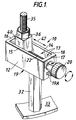
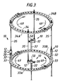
- Figures 1-3 illustrate the preferred embodiment of the apparatus of the present invention designated generally by the numeral 10, used for translation/rotation adjustments of one fixation ring 33 with respect to another ring 34.
- apparatus 10 including a base member 12 having a slot 13 surrounded by flat side walls 14, 15 defining the generally rectangular slot 13 there between. End walls 16, 17 are positioned at each end portion of the slot and the slot preferably has an open top 18 and an open bottom 19.
- the bottom of the slot 19 preferably communicates with a T-shaped longitudinally extending track 19A as shown in Figures 1 and 9.
- the track 19A provides an attachment for the affixation of tie rod 32 to base 12.
- Tie rod 32 has a similarly shaped, T-shaped upper head portion (not shown) which registers with the T-shaped slot 19A as shown in Figures 1 and 3.
- the connection between tie rod 32 and base 12 is preferably a bolted connection with threaded bolt 35 having a head portion that registers in and fits slot 19A.
- a cylindrical threaded shank of the bolt passes through a hollow central cylindrical bore of tie rod 32 and through a selected opening 31 of plate 33.
- a bolted connection 36 then secures the tie rod to ring 33.
- Rotatable thumb screw 20 provided a fine adjustment for translation and/or rotation of one ring 33 with respect to another ring 34.
- Thumb screw 20 includes set screw 21 mounted in opening 23 for connecting thumb screw 20 to end portion 29 of threaded shaft 22 for rotation therewith.
- Bushing 25 mounts in opening 27 of base member 12.
- Similarly shaped bushing 24 mounts in similarly shaped opening 26 opposite opening 27 as shown in Figure 2.
- Each bushing 24, 25 has an opening 30, 31 respectively through which threaded shaft 22 extends.
- the end portion 29 of shaft 22 registers with opening 30 of bushing 25, and end portion 28 which inserts through and registers with opening 30 of bushing 24.
- the end portions 28, 29 define unthreaded end sections of shaft 22. Otherwise, shaft 22 is threaded externally along its length as shown in Figure 2.
- Each ring 33, 34 provides a plurality of radially spaced openings 30, 31 respectively which accommodate tie rods 32, 33.
- Bolts 36 can be used to attach tie rods 35 to rings 33, 34 as shown in Figures 1, 3, and 4-6.
- Shaft 22 engages translator block 40 at threaded longitudinal bore 47.
- rotation of shaft 22 causes translator block 40 to move in slot 13 between end wall 16 and end wall 17.
- Block 40 is sized to fit in slot 13 as shown in Figure 1.
- Block 40 includes end walls 43, 44 and side walls 41, 42 as well as an upper surface 45 having a vertical threaded bore 46 therein. Threaded opening 46 accepts tie rods as shown in Figures 1 and 3.
- arrow 47 illustrates the translational movement of block 40 with respect to base 12 and thus the translational movement of tie rod 35 with respect to tie rod 32.
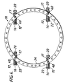
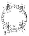
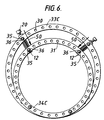
- Figures 4-6 illustrate translation of one ring 33 with respect to another ring 34.
- Figure 5 is a top view showing that the ring members 33, 34 have moved laterally with respect to one another.
- arrows 50 indicate a translational movement of a smaller upper ring 34C with respect to a larger lower ring 33C.
- FIG 3 an arrangement is illustrated for rotation of lower ring 33 with respect to upper ring 34.
- half rings 33A, 33B are shown formed into rings with bolted connections.
- Curved arrows 49 in Figure 3 illustrate the rotation and arrows 50 indicate the translational movement of block 40 with respect to base 12.
- the bases are affixed at 90 degrees with respect to one another as shown in the drawing so that the combination of all four travelling blocks 40 with respect to their bases 12 causes a rotation of the ring 34 with respect to the ring 33.
Landscapes
- Health & Medical Sciences (AREA)
- Orthopedic Medicine & Surgery (AREA)
- Life Sciences & Earth Sciences (AREA)
- Surgery (AREA)
- Biomedical Technology (AREA)
- Engineering & Computer Science (AREA)
- Nuclear Medicine, Radiotherapy & Molecular Imaging (AREA)
- Heart & Thoracic Surgery (AREA)
- Medical Informatics (AREA)
- Molecular Biology (AREA)
- Animal Behavior & Ethology (AREA)
- General Health & Medical Sciences (AREA)
- Public Health (AREA)
- Veterinary Medicine (AREA)
- Surgical Instruments (AREA)
Applications Claiming Priority (2)
| Application Number | Priority Date | Filing Date | Title |
|---|---|---|---|
| US598046 | 1990-10-16 | ||
| US07/598,046 US5074866A (en) | 1990-10-16 | 1990-10-16 | Translation/rotation device for external bone fixation system |
Publications (1)
| Publication Number | Publication Date |
|---|---|
| EP0481697A1 true EP0481697A1 (de) | 1992-04-22 |
Family
ID=24394007
Family Applications (1)
| Application Number | Title | Priority Date | Filing Date |
|---|---|---|---|
| EP91309410A Ceased EP0481697A1 (de) | 1990-10-16 | 1991-10-14 | Längs- oder Drehbewegungsvorrichtung für Knochenfixierungsgerät |
Country Status (5)
| Country | Link |
|---|---|
| US (1) | US5074866A (de) |
| EP (1) | EP0481697A1 (de) |
| JP (1) | JPH07416A (de) |
| AU (1) | AU636828B2 (de) |
| CA (1) | CA2053466A1 (de) |
Cited By (2)
| Publication number | Priority date | Publication date | Assignee | Title |
|---|---|---|---|---|
| EP0611007A1 (de) * | 1993-02-12 | 1994-08-17 | Bristol-Myers Squibb Company | Verstellbares Verbindungselement für externe Fixationsstäbe |
| EP1153575A1 (de) * | 2000-05-09 | 2001-11-14 | ORTHOFIX S.r.l. | Ringfixateur |
Families Citing this family (34)
| Publication number | Priority date | Publication date | Assignee | Title |
|---|---|---|---|---|
| US5275598A (en) * | 1991-10-09 | 1994-01-04 | Cook Richard L | Quasi-isotropic apparatus and method of fabricating the apparatus |
| US5358504A (en) * | 1993-05-05 | 1994-10-25 | Smith & Nephew Richards, Inc. | Fixation brace with focal hinge |
| GB2299545B (en) * | 1995-04-04 | 1998-07-29 | Capper Rataud Limited | Method of decoration |
| US5676664A (en) * | 1995-11-27 | 1997-10-14 | Zimmer, Inc. | Orthopaedic distractor and/or fixator |
| US5645548A (en) * | 1996-02-15 | 1997-07-08 | Augsburger; Samuel F. | Osteotomy frame |
| US5885282A (en) * | 1997-05-09 | 1999-03-23 | The Regents Of The University Of California | Apparatus for treatment of fracture and malunion of the distal radius |
| US5941879A (en) * | 1997-11-18 | 1999-08-24 | Electro-Biology, Inc. | Method and apparatus for external fixation of bones |
| US6277118B1 (en) | 2000-01-31 | 2001-08-21 | Electro-Biology, Inc. | External fixator including an angular correction module and related method |
| US6355037B1 (en) | 2000-12-05 | 2002-03-12 | Smith & Nephew, Inc. | Apparatus and method of external skeletal support allowing for internal-external rotation |
| GB0119104D0 (en) * | 2001-08-06 | 2001-09-26 | Patterson Noble | Walking aid |
| ITBO20020309A1 (it) * | 2002-05-20 | 2003-11-20 | Citieffe Srl | Fissatore esterno per il trattamento delle fratture delle ossa |
| US7282052B2 (en) * | 2002-09-17 | 2007-10-16 | Ebi, L.P. | Unilateral fixator |
| CA2505744C (en) * | 2002-11-14 | 2012-05-29 | Visionmed, Llc | Method for using a fixator device |
| US8758343B2 (en) | 2005-04-27 | 2014-06-24 | DePuy Synthes Products, LLC | Bone fixation apparatus |
| US7306601B2 (en) * | 2005-06-10 | 2007-12-11 | Quantum Medical Concepts, Inc. | External fixation system with provisional brace |
| DE102009040307A1 (de) * | 2009-09-05 | 2011-03-10 | Arne Jansen | Vorrichtung zum Fixieren von Knochensegmenten |
| US8858555B2 (en) | 2009-10-05 | 2014-10-14 | Stryker Trauma Sa | Dynamic external fixator and methods for use |
| GB201008281D0 (en) | 2010-05-19 | 2010-06-30 | Nikonovas Arkadijus | Indirect analysis and manipulation of objects |
| EP2417924B1 (de) | 2010-08-11 | 2015-07-01 | Stryker Trauma SA | Externes Befestigungssystem |
| US8945128B2 (en) | 2010-08-11 | 2015-02-03 | Stryker Trauma Sa | External fixator system |
| US11141196B2 (en) | 2010-08-11 | 2021-10-12 | Stryker European Operations Holdings Llc | External fixator system |
| US9101398B2 (en) | 2012-08-23 | 2015-08-11 | Stryker Trauma Sa | Bone transport external fixation frame |
| US9039706B2 (en) | 2013-03-13 | 2015-05-26 | DePuy Synthes Products, Inc. | External bone fixation device |
| JP6382293B2 (ja) | 2013-03-13 | 2018-08-29 | デピュイ・シンセス・プロダクツ・インコーポレイテッド | 外部骨固定装置 |
| US9962188B2 (en) | 2013-10-29 | 2018-05-08 | Cardinal Health 247. Inc. | External fixation system and methods of use |
| US10835318B2 (en) | 2016-08-25 | 2020-11-17 | DePuy Synthes Products, Inc. | Orthopedic fixation control and manipulation |
| CN108478266B (zh) * | 2018-03-26 | 2020-11-06 | 天津大学 | 自由连接式三支链并联骨科外固定支架 |
| US12274475B2 (en) | 2018-10-04 | 2025-04-15 | Peter M. Stevens | Automated coupled torsional fixators and method of use |
| US11272957B2 (en) * | 2018-10-04 | 2022-03-15 | University Of Utah Research Foundation | Coupled torsional fixator and method of use |
| US11439436B2 (en) | 2019-03-18 | 2022-09-13 | Synthes Gmbh | Orthopedic fixation strut swapping |
| US11304757B2 (en) | 2019-03-28 | 2022-04-19 | Synthes Gmbh | Orthopedic fixation control and visualization |
| WO2021069078A1 (en) * | 2019-10-10 | 2021-04-15 | Metlase Limited | External fixator |
| US11334997B2 (en) | 2020-04-03 | 2022-05-17 | Synthes Gmbh | Hinge detection for orthopedic fixation |
| CN111388074B (zh) * | 2020-04-20 | 2025-03-25 | 国家康复辅具研究中心 | 一种用于肢体畸形矫正的骨外固定器旋转调节机构 |
Citations (3)
| Publication number | Priority date | Publication date | Assignee | Title |
|---|---|---|---|---|
| US2198871A (en) * | 1936-08-04 | 1940-04-30 | Edward J Haboush | Fracture reducing and limb lengthening device |
| GB1481585A (en) * | 1975-06-10 | 1977-08-03 | Tsnii Travmatol I Ortoped Im N | Apparatus for surgical treatment of fractured bones or of bone joints |
| US4615338A (en) * | 1985-09-18 | 1986-10-07 | Kurgansky Nauchno-Issledovatelsky Institut Experimentalnoi I Klinicheskoi Ortopedii I Travmatologii | Automatic compression-distraction apparatus |
Family Cites Families (16)
| Publication number | Priority date | Publication date | Assignee | Title |
|---|---|---|---|---|
| SU98471A1 (ru) * | 1952-06-09 | 1953-11-30 | Г.А. Илизаров | Способ сращивани костей при переломах и аппарат дл осуществлени этого способа |
| SU367858A1 (ru) * | 1970-03-06 | 1973-01-26 | М. И. Синило С. Д. Саранча , А. Г. Надеин Ворошиловградский государственный медицинский институт | Компрессионно-дистракционный аппарат |
| SU507315A1 (ru) * | 1973-12-14 | 1976-03-25 | Рижский Научно-Исследовательский Институт Травматологии И Ортопедии | Кольцо дл компрессионно-дистракционного аппарата |
| SU517196A1 (ru) * | 1974-07-22 | 1977-09-25 | Центральный Ордена Трудового Красного Знамени Научно-Исследовательского Институт Травматологии И Ортопедии | Аппарат дл репозиции и фиксации костных отломков |
| US3977397A (en) * | 1974-11-27 | 1976-08-31 | Kalnberz Viktor Konstantinovic | Surgical compression-distraction instrument |
| CH630798A5 (fr) * | 1979-01-16 | 1982-07-15 | Jaquet Orthopedie | Fixateur externe pour osteosynthese. |
| SU829105A1 (ru) * | 1979-07-24 | 1981-05-15 | Datsko Aleksandr A | Устройство дл лечени переломовНижНЕй чЕлюСТи |
| SU848011A1 (ru) * | 1979-11-16 | 1981-07-23 | Горьковский Государственный Научно- Исследовательский Институт Травматологии И Ортопедии | Компрессионно-дистракционныйАппАРАТ |
| SU865284A1 (ru) * | 1980-01-11 | 1981-09-23 | Курганский Научно-Исследовательский Институт Экспериментальной И Клинической Ортопедии И Травматологии | Компрессионно-дистракционный аппарат |
| SU986404A1 (ru) * | 1981-02-19 | 1983-01-07 | за витель , К. М. Кауошы | Компрессионно-дистракционный аппарат |
| SU1066579A1 (ru) * | 1982-02-12 | 1984-01-15 | Саратовский Государственный Научно-Исследовательский Институт Травматологии И Ортопедии | Аппарат дл лечени контрактур коленного сустава |
| SU1076108A1 (ru) * | 1982-02-25 | 1984-02-29 | Gurev Valentin N | Устройство дл лечени переломов костей |
| SU1074512A1 (ru) * | 1982-05-17 | 1984-02-23 | Карагандинский государственный медицинский институт | Аппарат дл репозиции и внеочагового остеосинтеза костей голени |
| SU1149959A1 (ru) * | 1983-11-30 | 1985-04-15 | Labenskij Stepan V | Устройство дл репозиции и фиксации костных отломков |
| US4620533A (en) * | 1985-09-16 | 1986-11-04 | Pfizer Hospital Products Group Inc. | External bone fixation apparatus |
| AU2911789A (en) * | 1988-05-26 | 1989-12-12 | Vsesojuzny Kurgansky Nauchny Tsentr -Vosstanovitelnaya Travmatologia I Ortopedia | Device with automatic traction for osteosynthesis |
-
1990
- 1990-10-16 US US07/598,046 patent/US5074866A/en not_active Expired - Fee Related
-
1991
- 1991-10-14 AU AU85822/91A patent/AU636828B2/en not_active Ceased
- 1991-10-14 EP EP91309410A patent/EP0481697A1/de not_active Ceased
- 1991-10-15 CA CA002053466A patent/CA2053466A1/en not_active Abandoned
- 1991-10-16 JP JP3267866A patent/JPH07416A/ja active Pending
Patent Citations (3)
| Publication number | Priority date | Publication date | Assignee | Title |
|---|---|---|---|---|
| US2198871A (en) * | 1936-08-04 | 1940-04-30 | Edward J Haboush | Fracture reducing and limb lengthening device |
| GB1481585A (en) * | 1975-06-10 | 1977-08-03 | Tsnii Travmatol I Ortoped Im N | Apparatus for surgical treatment of fractured bones or of bone joints |
| US4615338A (en) * | 1985-09-18 | 1986-10-07 | Kurgansky Nauchno-Issledovatelsky Institut Experimentalnoi I Klinicheskoi Ortopedii I Travmatologii | Automatic compression-distraction apparatus |
Cited By (5)
| Publication number | Priority date | Publication date | Assignee | Title |
|---|---|---|---|---|
| EP0611007A1 (de) * | 1993-02-12 | 1994-08-17 | Bristol-Myers Squibb Company | Verstellbares Verbindungselement für externe Fixationsstäbe |
| US5405347A (en) * | 1993-02-12 | 1995-04-11 | Zimmer, Inc. | Adjustable connector for external fixation rods |
| EP1153575A1 (de) * | 2000-05-09 | 2001-11-14 | ORTHOFIX S.r.l. | Ringfixateur |
| WO2001085041A1 (en) | 2000-05-09 | 2001-11-15 | Orthofix S.R.L. | Ring fixator |
| US7226449B2 (en) | 2000-05-09 | 2007-06-05 | Orthofix S.R.L. | Ring fixator |
Also Published As
| Publication number | Publication date |
|---|---|
| AU636828B2 (en) | 1993-05-06 |
| AU8582291A (en) | 1992-04-30 |
| CA2053466A1 (en) | 1992-04-17 |
| JPH07416A (ja) | 1995-01-06 |
| US5074866A (en) | 1991-12-24 |
Similar Documents
| Publication | Publication Date | Title |
|---|---|---|
| US5074866A (en) | Translation/rotation device for external bone fixation system | |
| KR100477282B1 (ko) | 공간프레임 | |
| US6162223A (en) | Dynamic wrist fixation apparatus for early joint motion in distal radius fractures | |
| EP0029298B1 (de) | Externe Fixierungsvorrichtung, insbesondere für Knochenbrüche | |
| EP0216563B1 (de) | Externer Fixierungsapparat für Knochen | |
| US8628530B2 (en) | External fixation apparatus with angularly adjustable drill guiding and pin clamping means | |
| US5885282A (en) | Apparatus for treatment of fracture and malunion of the distal radius | |
| CA2361117C (en) | Spinal fixation system | |
| US4554915A (en) | Bone fixation frame | |
| US4450834A (en) | External fixation device | |
| KR0184525B1 (ko) | 외부 고정기 | |
| US8123747B2 (en) | Apparatus for external fixation of a fractured distal radius with angularly adjustable pin clamping means | |
| US7153302B1 (en) | Device for external fixation of bone fractures with clamping of multiple pins and with a fixture for applying extension to bone fragments | |
| US20030109879A1 (en) | External fixator for distal radius fractures | |
| US20030225405A1 (en) | Fixator with outrigger | |
| US5827283A (en) | Device and method for locating two bones into a desired relative position | |
| GB2324038A (en) | Fracture reduction device | |
| JP2005527314A (ja) | アウトリガーを備える骨固定器 | |
| KR20000062352A (ko) | 위치조정가능한 척주 골봉합 시스템 | |
| US6197027B1 (en) | Device for external fixation of a fractured radius | |
| EP1028666A1 (de) | Äusserer fixateur für frakturen der distalen speiche | |
| RU2010556C1 (ru) | Способ лечения перелома длинной трубчатой кости и устройство для его осуществления | |
| WO2010077309A2 (en) | External fixation apparatus with adjustable pin clamping means and convergent bone pins | |
| US20240148412A1 (en) | Stable locking fixation of threaded bone pins and other components of ring external fixator | |
| RU215861U1 (ru) | Устройство внешней чрескостной репозиции и фиксации для остеосинтеза стопы |
Legal Events
| Date | Code | Title | Description |
|---|---|---|---|
| PUAI | Public reference made under article 153(3) epc to a published international application that has entered the european phase |
Free format text: ORIGINAL CODE: 0009012 |
|
| 17P | Request for examination filed |
Effective date: 19911030 |
|
| AK | Designated contracting states |
Kind code of ref document: A1 Designated state(s): AT BE CH DE DK ES FR GB IT LI LU NL SE |
|
| 17Q | First examination report despatched |
Effective date: 19931027 |
|
| STAA | Information on the status of an ep patent application or granted ep patent |
Free format text: STATUS: THE APPLICATION HAS BEEN REFUSED |
|
| 18R | Application refused |
Effective date: 19960407 |