EP0481726B1 - Sockel für ein elektrisches Teil - Google Patents
Sockel für ein elektrisches Teil Download PDFInfo
- Publication number
- EP0481726B1 EP0481726B1 EP91309481A EP91309481A EP0481726B1 EP 0481726 B1 EP0481726 B1 EP 0481726B1 EP 91309481 A EP91309481 A EP 91309481A EP 91309481 A EP91309481 A EP 91309481A EP 0481726 B1 EP0481726 B1 EP 0481726B1
- Authority
- EP
- European Patent Office
- Prior art keywords
- contact
- electric part
- pivotable lever
- socket
- fulcrum
- Prior art date
- Legal status (The legal status is an assumption and is not a legal conclusion. Google has not performed a legal analysis and makes no representation as to the accuracy of the status listed.)
- Expired - Lifetime
Links
- 230000002093 peripheral effect Effects 0.000 claims 1
- 238000006073 displacement reaction Methods 0.000 description 9
- 239000002184 metal Substances 0.000 description 4
- 238000009825 accumulation Methods 0.000 description 2
- 230000000881 depressing effect Effects 0.000 description 1
- 230000000994 depressogenic effect Effects 0.000 description 1
- 230000037431 insertion Effects 0.000 description 1
- 238000003780 insertion Methods 0.000 description 1
- 239000000463 material Substances 0.000 description 1
- 238000000465 moulding Methods 0.000 description 1
Images
Classifications
-
- H—ELECTRICITY
- H05—ELECTRIC TECHNIQUES NOT OTHERWISE PROVIDED FOR
- H05K—PRINTED CIRCUITS; CASINGS OR CONSTRUCTIONAL DETAILS OF ELECTRIC APPARATUS; MANUFACTURE OF ASSEMBLAGES OF ELECTRICAL COMPONENTS
- H05K7/00—Constructional details common to different types of electric apparatus
- H05K7/02—Arrangements of circuit components or wiring on supporting structure
- H05K7/10—Plug-in assemblages of components, e.g. IC sockets
- H05K7/1015—Plug-in assemblages of components, e.g. IC sockets having exterior leads
- H05K7/1023—Plug-in assemblages of components, e.g. IC sockets having exterior leads co-operating by abutting, e.g. flat pack
Definitions
- This invention relates to a zero insertion type socket for an electric part including a means for displacing a contact between a contacted position and a released position.
- a contact itself includes a cantilevered arm projecting outwardly.
- a curved spring portion which is provided to the contact itself, is flexed in the compressing direction to realize an outward displacement as a component of force, thereby to separate a contact nose portion away from a contact of an IC, so that the IC can be inserted and removed with no load.
- the operational force for pushing down the presser cover and the contacting force of the contact are determined by the spring portion of the contact.
- the conventional IC socket had such incompatible problems as just mentioned. Therefore, it was difficult for the conventional IC socket to be such designed as to satisfy both the requirements for reducing the operational force as much as possible and increasing the contacting force.
- the constitution where the spring portion is compressed in order to obtain an outward displacement motion by pushing down the cantilevered arm has such inconveniences as that the outward displacement amount realized as a component of force relative to the pushing down amount is very limited, and an efficient amount of displacement is unobtainable relative to the pushing down amount.
- Another object of the present invention is to provide a socket for an electric part capable of causing an efficient outward displacement upon pushing down operation and thus, capable of obtaining a sufficient amount of outward displacement with a limited pushing down amount.
- a further object of the present invention is to provide a socket for an electric part capable of solving such problems as twisting of a contact resulting from a pushing down operation and metal fatigue of a cantilevered arm, and of soundly displacing the contact even if the socket is used repeatedly.
- a socket for an electric part including a pivotable lever disposed along a row of contacts each having a contact nose portion and a spring portion, one end of the pivotable lever being solidly connected with the contact and the other end thereof being extended outwardly from the engaging portion, the pivotable lever being supported such as to be pivoted while sliding on an idle fulcrum, the pivotable lever, when the other end thereof is pushed down, being pivoted while sliding on the idle fulcrum to permit the connecting portion to displace a contact nose of the contact outwardly against resiliency of the spring portion, so that the contact nose is separated away from a contact of an electric part thus enabling to insert and remove the electric part with no load.
- the pivotable lever When the pushing down force exerted to the other end portion of the pivotable lever is released, the pivotable lever is pivoted upwardly and sliding by resiliency of the spring portion of the contact and then waits for the next pushing down operation. At the same time, the contact is displaced inwardly by being biased by spring portion and brought into contact with the the upper surface of the contact of the electric part under pressure.
- the spring portion of the contact can be arranged to have such a spring constant as being contacted with the contact of the electric part with a proper contacting force.
- the pivotable lever can be pushed down with a reduced operational force in accordance with the principle of lever. Even if the spring constant of the spring portion of the contact is set large, this is not directly resulted in increase of the pushing down force, and the pushing down force can be reduced by properly setting the distances of the operating portion and acting portion from the pivotal fulcrum of the pivotable lever. At the same time, the object for increasing the contacting force can also be achieved.
- the pivotable lever exerts an outward force directing upward at angles to the contact so that the contact is separated away from the contact of an electric part, the outward displacement of the contact can efficiently be realized relative to the pushing down force of the pivotable lever, and a sufficient space for accommodating the electric part can be released.
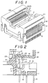
- FIG. 1 through 4 show the embodiment of the present invention, wherein:
- a base member 1 formed of an insulated material has a central opening 2 through its upper and lower surfaces.
- a space 3 for accommodating an electric part is defined on the upper surface side of the central opening 2.
- the base member 1 is provided with a plurality of contacts arranged in parallel relation along at least two opposed sides of the space 3.
- the contacts 4 are implanted in the base member 1.
- Each contact 4 includes a male terminal 5 extending downward from a lower surface of the base member 1.
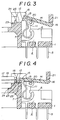
- the contact 4 also includes a flat portion 6 connected next to a basal portion of the male terminal 5.
- the flat portion 6 is supported on and vertically erected from an upper surface of an implanted wall of the contact.
- the contact 4 further includes a spring portion 7 connected next to an inner edge of an upper end of the flat portion 6.
- the spring portion 7 has a curved shape extending downward from its connected portion (basal portion 8) with the flat portion 6 and then curved back to the vicinity of the connected portion. In other words, the spring portion 7 has a downwardly directed curved shape.
- An angle of the curve is set such that a predetermined small distance 10 is formed between the basal portion 8 and a distal end 9 of the spring portion 7 extending from the basal portion 8.
- This angle of the curve is preferably set to 180 degrees or more, and more preferably to 250 degrees or more.
- the spring portion 7 is curved such that the distal end 9 thereof reaches the vicinity of an upper end of a vertical center line Y of the curved spring portion 7.
- the contact 4 further includes a contact arm 11 connected next to the distal end 9 of the curved spring portion 9 and inclining inwardly.
- the contact arm 11 terminates in a contact nose projecting inwardly and and downwardly from its distal end.
- the spring portion 7 urges the contact arm 11 and the contact nose 12 inwardly so that the contact nose 12 is brought into contact with a contact 18 of an electric part 17 represented by IC.
- the contact 4 further includes an engaging element 13 extending upwardly from the distal end of the arm 11, that is, from the connected portion between the arm 11 and the contact nose 12.
- An acting portion 15 of the pivotable lever 14 is brought into engagement with the engaging element 13.
- the pivotable lever 14 is extended in parallel relation with a row of the contacts 4 at the outer side of the contacts.
- the pivotable lever 14 is provided at one end thereof with an acting portion 15 and at the other end thereof with an operating portion 16 extending outward.
- the acting portion 15 is engaged with the engaging element 13.
- the engaging element 13 is integrally connected with the acting portion 15 of the pivotable lever 14.
- the engaging element 13 is integrally connected with the pivotable lever 14 by molding or otherwise the engaging element 13 is press fitted into the pivotable lever 14 for integral connection.
- the pivotable lever 14 forms a the operating portion 16 extending outwardly from the engaged portion. Accordingly, the pivotable lever 14 itself has a pivotal fulcrum, while forming a part of the contact 4.
- the fulcrum of the pivotable lever 14 is an idle fulcrum which moves tracing a certain orbit.
- the drawings show one example of the structure of the idle fulcrum.
- the pivotable lever 14 is placed on a guide shaft 20 disposed on the base member 1 side at a mid-way of the pivotable lever 14, i.e., somewhere between the acting portion 15 and the operating portion 16 and supported thereon such that the pivotable lever 14 is pivoted upwardly and downwardly while sliding on the surface of the guide shaft 20.
- the pivotal fulcrum moves about the guide shaft 20. That is, when the operating portion 16 is pushed down from the state shown in Fig.
- the pivotable lever 14 is pivoted downwardly while sliding on the surface of the guide shaft 20 from its upper dead point toward its lower dead point, and the acting portion 15 exerts an outward force to a free end of the contact 4 through the engaged portion to realize an outward displacement against the resiliency of the spring portion 7 as shown in Fig. 3.
- the contact nose portion 12 is moved to a non-contacting position to form an non-interference state with the electric part 17. In that state, the electric part 17 can freely be inserted and removed.
- the pivotable lever 14 is pivoted upwardly while sliding on the surface of the guide shaft 20 by the resiliency of the spring portion 7.
- the contact 4 is displaced inwardly by the resiliency of the spring portion 7 to urge the contact nose portion 12 against the upper surface of the contact 18 of the electric part.
- a pivotal movement about an idle fulcrum can be realized by bringing the fulcrum of the pivotable lever 14 into slide engagement with a face cam or a groove cam.
- a plurality of pivotable levers 14 can be provided per row of the contacts 4. In other words, one group of contacts arranged in a row can be divided into small groups of contacts, and the small groups of contacts can be displaced by separate pivotable levers.
- the pivotable lever 14 can directly be pushed down by robot or by manual operation at the operating portion 16. As shown in Fig.
- the cover 21 is disposed over the base member 1, and a central window 22 formed in the cover 21 is faced with the electric part accommodating space 3 of the base member 1, so that the electric part 17 can be inserted into and removed from the space 3 through the central window 22.
- the lower surface of the presser cover 21 is placed on the operating portion 16 of the pivotable lever 14, and the operating portion 16 is pushed down by depressing the presser cover 21 by robot or by manual operation.
- a wall 23 defining the electric part accommodating space 3 is provided with a positioning ridge 24 projecting upwardly therefrom, so that the side of the electric part's body 19 is supported by the positioning ridge 24. Further, the lower surface of the contact 18 is supported by a contact supporting surface 25 formed on the upper surface of the wall 23 at the outer side of the positioning ridge 24, and the contact nose 12 is brought into contact with the upper surface of such supported contact 18 under a downward pressure.
- the contact nose 12 is in contact with the contact supporting surface 25 so that the contact 4 is not displaced inwardly by a predetermined amount or more.
- the contact supporting surface 25 forms a stopper for limiting the inwardly displacing amount of the contact 4.
- the operating portion 16 of the pivotable lever 14 is normally upwardly pivoted to a fixed position by the elasticity of the contact 4 and held in a waiting state.
- the pivotable lever 14 when the pivotable lever 14 is pushed down at the operating portion 16, the pivotable lever 14 is pivoted downwardly while moving the fulcrum on the surface of the guide shaft 20. That is, the pivotable lever 14 is pivoted about the idle fulcrum. By this, an outward displacement of the contact 4 is effectively made by the acting portion 15. More specifically, at an initial stage of the downward pivotal movement about the idle fulcrum, the pivotable lever 14 is continuously pivoted about the idle fulcrum to displace the contact nose portion 12 backwardly while effectively generating a force for pulling up the contact nose portion 7 of the contact 4. In other words, the pivotable lever 14 can efficiently separate the contact nose portion 12 of the contact 4 upwardly at angles away from the contact 18 of the electric part.
- the spring portion of the contact can be set to have such a spring constant as being able to contact with the contact of the electric part with a proper contacting force. Accordingly, the contact can be freely designed without being restricted by the operating force of the pivotable lever. On the other hand, the pivotable lever can be pushed down with a reduced force in accordance with the principle of lever. Even if the spring constant of the spring portion of the contact is increased, this does not directly lead to the increase of the pushing down force. By properly setting the distances of the operating portion and acting portion from the guide shaft supporting the pivotable lever, the operating force can be reduced. As a result, the object for increasing the contacting force can also be achieved while realizing a reduced operating force.
- the acting portion of the contact displaces the contact outwardly to separate the contact nose portion from the contact of the electric part while pulling up the contact nose portion at the initial stage of the pivotal movement, the contact can efficiently be displaced outwardly upon pushing-down operation of the pivotable lever.
- the electric part accommodating space can be sufficiently released.
- the pivotable lever is pivoted downward about the idle fulcrum while sliding on the surface of the guide shaft, it can efficiently pull up the contact nose portion of the contact.
Landscapes
- Engineering & Computer Science (AREA)
- Microelectronics & Electronic Packaging (AREA)
- Connecting Device With Holders (AREA)
- Coupling Device And Connection With Printed Circuit (AREA)
Claims (2)
- Sockel für ein elektrisches Teil (17) mit einer Aufnahme (3) für das Teil (17) und einer Mehrzahl von an mindestens zwei einander gegenüberliegenden Seiten der Aufnahme (3) in Abständen parallel zueinander verlaufend angeordneten Kontakten (4) mit jeweils einer mit einem Anschlußkontakt (18) des in die Aufnahme (3) eingefügten elektrischen Teil (17) Kontakt eingehenden Kontaktnase (12) und einem die Nase (12) unter Erzeugung eines hinreichenden Anpreßdrucks in Kontakt mit dem Anschlußkontakt (18) des elektrischen Teils (17) überführenden Federbereich (7), dadurch gekennzeichnet, daß dem Sockel entlang einer Reihe von Kontakten (4) ein verschwenkbarer Hebel (14) zugeordnet ist, dessen eines Ende (15) mit den Kontakten (4) verbunden ist (13) und dessen anderes Ende sich von dem mit den Kontakten (4) zusammengefaßten (13) Ende (15) nach außen weg erstreckt, wobei der Hebel (14) auf einer Hebelstütze verschwenkbar auf dieser Stütze quer dazu verlagerbar gelagert ist, so daß der Hebel (14) beim Absenken seines freien Endes (16) auf der Hebelstütze verschwenkend und sich quer dazu verlagernd die Kontaktnase (12) der Kontakte (4) von dem jeweiligen Anschlußkontakt (18) des elektrischen Teils (17) gegen die Rückstellkraft des Federbereichs (7) der Kontakte (4) abhebt.
- Sockel für ein elektrisches Teil (17) nach Anspruch 1, dadurch gekennzeichnet, daß der Hebel (14) von einer Achse (20) sich am Unfang der Achse (20) frei abstützend unterfangen ist.
Applications Claiming Priority (4)
| Application Number | Priority Date | Filing Date | Title |
|---|---|---|---|
| JP278461/90 | 1990-10-17 | ||
| JP2278461A JPH0632241B2 (ja) | 1990-10-17 | 1990-10-17 | 電気部品用ソケット |
| SG148994A SG148994G (en) | 1990-10-17 | 1994-10-13 | Socket for electric part |
| SG149294A SG149294G (en) | 1990-10-17 | 1994-10-13 | Socket for electric part |
Publications (2)
| Publication Number | Publication Date |
|---|---|
| EP0481726A1 EP0481726A1 (de) | 1992-04-22 |
| EP0481726B1 true EP0481726B1 (de) | 1994-05-11 |
Family
ID=27336559
Family Applications (2)
| Application Number | Title | Priority Date | Filing Date |
|---|---|---|---|
| EP91309481A Expired - Lifetime EP0481726B1 (de) | 1990-10-17 | 1991-10-15 | Sockel für ein elektrisches Teil |
| EP91309482A Expired - Lifetime EP0481727B1 (de) | 1990-10-17 | 1991-10-15 | Sockel für ein elektrisches Teil |
Family Applications After (1)
| Application Number | Title | Priority Date | Filing Date |
|---|---|---|---|
| EP91309482A Expired - Lifetime EP0481727B1 (de) | 1990-10-17 | 1991-10-15 | Sockel für ein elektrisches Teil |
Country Status (5)
| Country | Link |
|---|---|
| US (1) | US5186641A (de) |
| EP (2) | EP0481726B1 (de) |
| JP (1) | JPH0632241B2 (de) |
| DE (2) | DE69101615T2 (de) |
| SG (2) | SG148994G (de) |
Families Citing this family (15)
| Publication number | Priority date | Publication date | Assignee | Title |
|---|---|---|---|---|
| JPH0736344B2 (ja) * | 1992-03-10 | 1995-04-19 | 山一電機株式会社 | 電気部品用ソケット |
| JPH0734380B2 (ja) * | 1992-03-10 | 1995-04-12 | 山一電機株式会社 | 電気部品用ソケット |
| JP2693343B2 (ja) * | 1992-07-07 | 1997-12-24 | 山一電機 株式会社 | 回路形成素子用ソケット |
| US5288240A (en) * | 1992-12-16 | 1994-02-22 | Minnesota Mining And Manufacturing Company | Top-load socket for integrated circuit device |
| JPH06105630B2 (ja) * | 1992-12-26 | 1994-12-21 | 山一電機株式会社 | Icソケット |
| JPH0752662B2 (ja) * | 1992-12-26 | 1995-06-05 | 山一電機株式会社 | Icソケット |
| JPH0831348B2 (ja) * | 1993-04-30 | 1996-03-27 | 株式会社秩父富士 | Icパッケージ用ソケット |
| US5477161A (en) * | 1993-06-18 | 1995-12-19 | Emulation Technology, Inc. | Test adapter for packaged integrated circuits |
| JPH0831349B2 (ja) * | 1993-07-13 | 1996-03-27 | 株式会社秩父富士 | Icパッケージ用ソケット |
| US5358421A (en) * | 1993-08-06 | 1994-10-25 | Minnesota Mining And Manufacturing Company | Zero-insertion-force socket for gull wing electronic devices |
| JP2667638B2 (ja) * | 1994-05-18 | 1997-10-27 | 山一電機株式会社 | Icソケット |
| US6162066A (en) * | 1997-05-16 | 2000-12-19 | Wells-Cti, Inc. | Socket for positioning and installing an integrated circuit chip on a flexible connector sheet |
| USD493427S1 (en) | 2002-07-26 | 2004-07-27 | Mitsumi Electric Co., Ltd. | Electrical connector |
| JP2010092616A (ja) * | 2008-10-03 | 2010-04-22 | Yamaichi Electronics Co Ltd | Icソケット |
| JP7065400B2 (ja) * | 2018-04-26 | 2022-05-12 | パナソニックIpマネジメント株式会社 | コンタクト、コネクタ及び接続装置 |
Family Cites Families (11)
| Publication number | Priority date | Publication date | Assignee | Title |
|---|---|---|---|---|
| US2965811A (en) * | 1957-08-08 | 1960-12-20 | Ralph R Batcher | Circuit selector device |
| FR2541827B1 (fr) * | 1983-02-25 | 1985-07-05 | Socapex | Connecteur comprenant au moins un contact presentant un bras elastiquement deformable |
| US4623208A (en) * | 1985-04-03 | 1986-11-18 | Wells Electronic, Inc. | Leadless chip carrier socket |
| JPH0775182B2 (ja) * | 1986-09-02 | 1995-08-09 | 日本テキサス・インスツルメンツ株式会社 | ソケツト |
| JPS63299257A (ja) * | 1987-05-29 | 1988-12-06 | Dai Ichi Seiko Co Ltd | Ic検査用ソケット |
| JP2784570B2 (ja) * | 1987-06-09 | 1998-08-06 | 日本テキサス・インスツルメンツ 株式会社 | ソケツト |
| US4836798A (en) * | 1987-12-21 | 1989-06-06 | Wells Electronics, Inc. | Zero insertion socket with normally closed contacts |
| US4886470A (en) * | 1988-05-24 | 1989-12-12 | Amp Incorporated | Burn-in socket for gull wing integrated circuit package |
| US4950980A (en) * | 1988-07-29 | 1990-08-21 | Pfaff Wayne | Test socket for electronic device packages |
| JP2670517B2 (ja) * | 1989-03-30 | 1997-10-29 | 山一電機株式会社 | Icキャリア搭載形ソケットにおける接触機構 |
| US4993955A (en) * | 1990-03-08 | 1991-02-19 | Minnesota Mining And Manufacturing Company | Top-load socket for integrated circuit device |
-
1990
- 1990-10-17 JP JP2278461A patent/JPH0632241B2/ja not_active Expired - Fee Related
-
1991
- 1991-10-15 DE DE69101615T patent/DE69101615T2/de not_active Expired - Fee Related
- 1991-10-15 EP EP91309481A patent/EP0481726B1/de not_active Expired - Lifetime
- 1991-10-15 DE DE69101962T patent/DE69101962T2/de not_active Expired - Fee Related
- 1991-10-15 EP EP91309482A patent/EP0481727B1/de not_active Expired - Lifetime
- 1991-10-16 US US07/777,114 patent/US5186641A/en not_active Expired - Lifetime
-
1994
- 1994-10-13 SG SG148994A patent/SG148994G/en unknown
- 1994-10-13 SG SG149294A patent/SG149294G/en unknown
Also Published As
| Publication number | Publication date |
|---|---|
| JPH04154065A (ja) | 1992-05-27 |
| US5186641A (en) | 1993-02-16 |
| DE69101615D1 (de) | 1994-05-11 |
| DE69101962D1 (de) | 1994-06-16 |
| EP0481727A1 (de) | 1992-04-22 |
| DE69101962T2 (de) | 1995-05-18 |
| DE69101615T2 (de) | 1994-11-17 |
| SG148994G (en) | 1995-03-17 |
| EP0481726A1 (de) | 1992-04-22 |
| JPH0632241B2 (ja) | 1994-04-27 |
| EP0481727B1 (de) | 1994-04-06 |
| SG149294G (en) | 1995-03-17 |
Similar Documents
| Publication | Publication Date | Title |
|---|---|---|
| EP0481726B1 (de) | Sockel für ein elektrisches Teil | |
| US4040697A (en) | Electrical connector | |
| US4973271A (en) | Low insertion-force terminal | |
| US5009609A (en) | Contact shutter device in IC socket | |
| JPH0736378U (ja) | 回路基板挿着用電気コネクタ | |
| US5195903A (en) | Socket for electric part | |
| US5037321A (en) | Connector for electric part | |
| EP0539073B1 (de) | Sockel für elektrisches Bauteil | |
| US5912445A (en) | Miniature pushbutton switch with coil spring contact | |
| US5752846A (en) | IC socket | |
| US5672072A (en) | Circuit board electrical connector | |
| US6392177B1 (en) | Tact switch connector | |
| CA2053511A1 (en) | Socket for electric part | |
| US5147212A (en) | Socket for electric part | |
| US6109944A (en) | IC socket having forwardly displaceable contacts with upper and lower contact pieces | |
| US4413873A (en) | Electrical tab receptacle | |
| CN110729603A (zh) | 一种杠杆式双弹力臂卡扣连接器 | |
| US4050759A (en) | Zero-insertion-withdrawal force connector | |
| EP0089807B1 (de) | Elektrische Flachsteckhülse mit einem beweglichen Verriegelungsglied | |
| CN210897836U (zh) | 一种杠杆式双弹力臂卡扣连接器 | |
| JPH0536870A (ja) | Icソケツト | |
| US5628645A (en) | IC socket | |
| KR0130438B1 (ko) | 록크핀의 변형을 방지하기 위한 푸쉬형 스위치 | |
| JP2708039B2 (ja) | Icソケット | |
| JP2667645B2 (ja) | Icソケットにおけるコンタクトの開閉機構 |
Legal Events
| Date | Code | Title | Description |
|---|---|---|---|
| PUAI | Public reference made under article 153(3) epc to a published international application that has entered the european phase |
Free format text: ORIGINAL CODE: 0009012 |
|
| AK | Designated contracting states |
Kind code of ref document: A1 Designated state(s): DE FR GB IT |
|
| 17P | Request for examination filed |
Effective date: 19920601 |
|
| 17Q | First examination report despatched |
Effective date: 19930722 |
|
| GRAA | (expected) grant |
Free format text: ORIGINAL CODE: 0009210 |
|
| AK | Designated contracting states |
Kind code of ref document: B1 Designated state(s): DE FR GB IT |
|
| PG25 | Lapsed in a contracting state [announced via postgrant information from national office to epo] |
Ref country code: IT Free format text: LAPSE BECAUSE OF FAILURE TO SUBMIT A TRANSLATION OF THE DESCRIPTION OR TO PAY THE FEE WITHIN THE PRE;WARNING: LAPSES OF ITALIAN PATENTS WITH EFFECTIVE DATE BEFORE 2007 MAY HAVE OCCURRED AT ANY TIME BEFORE 2007. THE CORRECT EFFECTIVE DATE MAY BE DIFFERENT FROM THE ONE RECORDED.SCRIBED TIME-LIMIT Effective date: 19940511 |
|
| REF | Corresponds to: |
Ref document number: 69101962 Country of ref document: DE Date of ref document: 19940616 |
|
| ET | Fr: translation filed | ||
| RAP2 | Party data changed (patent owner data changed or rights of a patent transferred) |
Owner name: YAMAICHI ELECTRONICS CO., LTD. |
|
| PGFP | Annual fee paid to national office [announced via postgrant information from national office to epo] |
Ref country code: FR Payment date: 19941028 Year of fee payment: 4 |
|
| PGFP | Annual fee paid to national office [announced via postgrant information from national office to epo] |
Ref country code: DE Payment date: 19941223 Year of fee payment: 4 |
|
| PLBE | No opposition filed within time limit |
Free format text: ORIGINAL CODE: 0009261 |
|
| STAA | Information on the status of an ep patent application or granted ep patent |
Free format text: STATUS: NO OPPOSITION FILED WITHIN TIME LIMIT |
|
| 26N | No opposition filed | ||
| PGFP | Annual fee paid to national office [announced via postgrant information from national office to epo] |
Ref country code: GB Payment date: 19951005 Year of fee payment: 5 |
|
| PG25 | Lapsed in a contracting state [announced via postgrant information from national office to epo] |
Ref country code: FR Effective date: 19960628 |
|
| PG25 | Lapsed in a contracting state [announced via postgrant information from national office to epo] |
Ref country code: DE Effective date: 19960702 |
|
| REG | Reference to a national code |
Ref country code: FR Ref legal event code: ST |
|
| PG25 | Lapsed in a contracting state [announced via postgrant information from national office to epo] |
Ref country code: GB Effective date: 19961015 |
|
| GBPC | Gb: european patent ceased through non-payment of renewal fee |
Effective date: 19961015 |