EP0481767A1 - Outil de coupe pour tubages - Google Patents
Outil de coupe pour tubages Download PDFInfo
- Publication number
- EP0481767A1 EP0481767A1 EP19910309549 EP91309549A EP0481767A1 EP 0481767 A1 EP0481767 A1 EP 0481767A1 EP 19910309549 EP19910309549 EP 19910309549 EP 91309549 A EP91309549 A EP 91309549A EP 0481767 A1 EP0481767 A1 EP 0481767A1
- Authority
- EP
- European Patent Office
- Prior art keywords
- motor
- fluid
- tubing
- fluid pressure
- tool
- Prior art date
- Legal status (The legal status is an assumption and is not a legal conclusion. Google has not performed a legal analysis and makes no representation as to the accuracy of the status listed.)
- Granted
Links
Images

Classifications
-
- E—FIXED CONSTRUCTIONS
- E21—EARTH OR ROCK DRILLING; MINING
- E21B—EARTH OR ROCK DRILLING; OBTAINING OIL, GAS, WATER, SOLUBLE OR MELTABLE MATERIALS OR A SLURRY OF MINERALS FROM WELLS
- E21B4/00—Drives for drilling, used in the borehole
- E21B4/18—Anchoring or feeding in the borehole
-
- E—FIXED CONSTRUCTIONS
- E21—EARTH OR ROCK DRILLING; MINING
- E21B—EARTH OR ROCK DRILLING; OBTAINING OIL, GAS, WATER, SOLUBLE OR MELTABLE MATERIALS OR A SLURRY OF MINERALS FROM WELLS
- E21B29/00—Cutting or destroying pipes, packers, plugs or wire lines, located in boreholes or wells, e.g. cutting of damaged pipes, of windows; Deforming of pipes in boreholes or wells; Reconditioning of well casings while in the ground
- E21B29/002—Cutting, e.g. milling, a pipe with a cutter rotating along the circumference of the pipe
- E21B29/005—Cutting, e.g. milling, a pipe with a cutter rotating along the circumference of the pipe with a radially-expansible cutter rotating inside the pipe, e.g. for cutting an annular window
Definitions
- This invention relates to a tubing cutting tool, and in the preferred embodiment provides a cutting tool suitable for use in an oil or gas well or the like.
- tubing cutting tool of the present invention is particularly suitable for cutting a tubing string located within a well, but the invention may be embodied in forms suitable for cutting other tubular elements whether or not forming part of an oil or gas well installation.
- a tubing cutting tool comprising a fluid powered rotary motor having a body and a rotary output member; fluid pressure responsive means for locking the body to the tubing to be cut when the pressure of the motor operating fluid exceeds a predetermined value; a rotary cutter connected to the rotary output member of the motor for rotation therewith, the rotary cutter having at least one cutting element which is normally located at a first radial distance from the longitudinal axis of the tool; and fluid pressure responsive means operable in response to the pressure of the motor operating fluid exceeding a second predetermined value to move the or each cutting element radially outwardly from its normal position to engage the tubing to be cut.
- the fluid pressure responsive means for locking the body to the tubing is responsive to fluid pressure upstream of the rotary motor, and the fluid pressure responsive means for moving the or each cutting element is responsive to fluid pressure downstream of the rotary motor.
- the fluid flow path for the motor operating fluid incorporates a restriction downstream of the second fluid pressure responsive means whereby an increase in fluid flow rate results in an increase in fluid pressure at both the first fluid pressure responsive means and the second fluid pressure responsive means.
- the preferred embodiment of the invention also includes a scraping or milling head which is connected to the rotary output member of the rotary motor and which may be rotated by the rotary motor for the purpose of cleaning the internal surface of the tubing within which the tool is located.
- the motor may be operated by fluid at a pressure less than the second predetermined pressure with the result that rotation of the motor will cause rotation of the scraping or milling tool, but will not cause the cutting elements to be moved radially outwardly into engagement with the tubing.
- the motor may be operated at a pressure less than the first predetermined pressure so that the scraping/milling tool may be rotated as the tool is moved through the tubing. For this purpose it is necessary to restrain the body of the motor against rotation, and this can conveniently be effected by connection the motor body to a suitable tubing string which is used for the purpose of moving the tool through the tubing to be cleaned and for communicating operating fluid to the motor.
- a tubing cutting tool 1 located within a length of tubing 2, for example a tubing string which itself is located within a well bore.
- the tool 1 comprises a plurality of interconnected subs and is connected at its upper end to a tubing string 3 by means of which the tool may be run through the tubing 2.
- the central bore 4 of the tubing string is used to carry an operating fluid, for example a mud, to the tool 1.
- the tool 1 comprises a rotary motor 5 which, in use, is driven by the flow of operating fluid therethrough.
- the body of the motor 5 is connected to an upper sub 6 which has mounted thereon a multiplicity of plungers 7.
- the plungers 7 are normally biased radially inwardly by suitable springs (not shown) so that the radially outer extremity of the plungers is flush with the surface of the sub 6.
- the radially inner ends of the plungers 7 are exposed via radial bores 8 to the fluid pressure within the sub 6 so that if the fluid presure exceeds a first predetermined value the plungers 7 are moved radially outwardly to engage the tubing 2.
- the radially outer ends of the plungers may be provided with suitable teeth or serrations, and may be hardened.
- the motor 5 includes a rotary output member 9 which is connected to a rotary cutter 10.
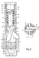
- the rotary cutter 10 is shown in more detail in Figure 2 and comprises a pair of cutting elements 11,12 which are pivotally mounted on a pin 13 which is secured to the body 14 of the rotary cutter.
- each cutting element 11,12 is suitably protected, e.g. by means of inserts or crushed particles of suitable hardening material e.g. tungsten carbide or cubic boron nitride.
- suitable hardening material e.g. tungsten carbide or cubic boron nitride.
- the cutting elements are located such that the radially outermost extremity of each cutting element is located within the body 14 of the rotary cutter.
- Each cutting element may, however, be pivoted to move the cutting edge thereof radially outwardly to engage the internal surface 15 of the tubing within which the tool is located.
- the radially outwardly extreme position of the cutting element 12 is illustrated on the right-hand side of Figure 2, and in this position the outermost point of the cutting element will have cut through the wall of the tubing 2.
- a fluid pressure responsive device is provided in the form of a piston 16 working in a cylinder 17. Seals 18,19 are provided between the piston 16 and the cylinder 17 and the piston is normally biased upwardly to the position illustrated on the right-hand half of Figure 2 by a spring 20. Further upward movement of the piston 16 is prevented by a spring clip 21 located within a groove in the cylinder wall.
- operating fluid exiting from the motor 5 is communicated through the central bore of the tool to the chamber 22 defined within the cylinder 17 above the piston 16. This fluid pressure acts downwardly on the piston 16. Fluid may leave the chamber 22 via passages 23 and may then flow through an annular passage 24 formed between the cylinder 17 and the body 14 to passages 25 located below the level of the cutting elements 11,12.
- the passages 23,25 provide a restriction to the flow of fluid whereby the pressure within the chamber 22 increases as flow rate of working fluid increases.
- Seals 26,27 are located between the cylinder 17 and the body 14 of the rotary cutter.
- the rotary cutter 10 is connected by a sub 28 to a scraping or milling tool 29 having an outside diameter 30 substantially corresponding to the internal diameter of the tubing 2.
- the tool 1 is run through the tubing 2 by means of a suitable tubing string. If it is desired to clean the internal surface 15 of the tubing a suitable working fluid, for example a mud, is pumped through the string to which the tool 1 is connected to flow through the motor 5 at a predetermined rate. This predetermined rate is sufficient to operate the motor and thereby rotate the rotary cutter 10 and with it the scraping/milling tool 30 to clean the interior surface of the tubing.
- a suitable working fluid for example a mud
- the tool is located at a suitable position and the flow rate of working fluid is increased.
- the increased flow rate causes the motor to operate at a faster speed and, due to the flow restriction provided by the motor itself and the passages 23,25 causes the fluid pressure within the tool to increase both upstream and downstream of the motor.
- the increased fluid pressure upstream of the motor is communicated via the passages 8 to the plungers 7, causing the plungers to move radially outwardly to grip the tubing to fix the motor body relative to the tubing.
- the fluid pressure downstream of the motor 5 operates within the chamber 22 to bias the piston 16 downwardly and thereby move the cutters 11,12 radially outwardly to engage the internal wall of the tubing.
- the tool described above may perform either a tube cleaning operation or a tube cutting operation, or a combination of these operations.
- the tool is relatively simple in construction and does not require withdrawal from the tubing for resetting after each cut has been made.
- the cylinder 17 may be integral with the body 14 and the chambers 22 and passages 23,25 bored accordingly. Plugs would be fitted to seal the upper end of the passage 24 running the length of the body connecting passages 23 and 25.
Landscapes
- Engineering & Computer Science (AREA)
- Life Sciences & Earth Sciences (AREA)
- Geology (AREA)
- Mining & Mineral Resources (AREA)
- Physics & Mathematics (AREA)
- Environmental & Geological Engineering (AREA)
- Fluid Mechanics (AREA)
- General Life Sciences & Earth Sciences (AREA)
- Geochemistry & Mineralogy (AREA)
- Mechanical Engineering (AREA)
- Drilling Tools (AREA)
- Earth Drilling (AREA)
- Milling Processes (AREA)
- Turning (AREA)
- Materials For Medical Uses (AREA)
- Bulkheads Adapted To Foundation Construction (AREA)
- Adornments (AREA)
- Sawing (AREA)
- Adhesives Or Adhesive Processes (AREA)
- Finish Polishing, Edge Sharpening, And Grinding By Specific Grinding Devices (AREA)
Applications Claiming Priority (2)
| Application Number | Priority Date | Filing Date | Title |
|---|---|---|---|
| GB9022424A GB2248792B (en) | 1990-10-16 | 1990-10-16 | Tubing cutting tool |
| GB9022424 | 1990-10-16 |
Publications (2)
| Publication Number | Publication Date |
|---|---|
| EP0481767A1 true EP0481767A1 (fr) | 1992-04-22 |
| EP0481767B1 EP0481767B1 (fr) | 1994-12-14 |
Family
ID=10683786
Family Applications (1)
| Application Number | Title | Priority Date | Filing Date |
|---|---|---|---|
| EP91309549A Expired - Lifetime EP0481767B1 (fr) | 1990-10-16 | 1991-10-16 | Outil de coupe pour tubages |
Country Status (8)
| Country | Link |
|---|---|
| EP (1) | EP0481767B1 (fr) |
| AT (1) | ATE115678T1 (fr) |
| DE (1) | DE69105910T2 (fr) |
| DK (1) | DK0481767T3 (fr) |
| ES (1) | ES2068521T3 (fr) |
| GB (1) | GB2248792B (fr) |
| GR (1) | GR3015402T3 (fr) |
| NO (1) | NO301992B1 (fr) |
Cited By (8)
| Publication number | Priority date | Publication date | Assignee | Title |
|---|---|---|---|---|
| EP0631646A4 (fr) * | 1992-03-25 | 1996-04-17 | Atlantic Richfield Co | Procede et appareil de decoupage et de fraisage de puits. |
| GB2305952A (en) * | 1995-10-05 | 1997-04-23 | Red Baron | Milling of well casings |
| WO1997044566A1 (fr) * | 1996-05-23 | 1997-11-27 | Wirth Maschinen- und Bohrgeräte-Fabrik GmbH | Procece et dispositif pour decouper des tubes ou des piliers ancres dans le sol |
| US6330919B1 (en) * | 1996-03-08 | 2001-12-18 | Smith International, Inc. | Method of removing wellhead assemblies and cutting assembly for use therein |
| RU2201493C2 (ru) * | 2001-05-28 | 2003-03-27 | Открытое акционерное общество "Акционерная нефтяная компания "Башнефть" | Вырезающее устройство |
| WO2011156107A3 (fr) * | 2010-06-07 | 2012-02-16 | Baker Hughes Incorporated | Coupe-tubage entraîné par moteur hydraulique et descendu par câble lisse |
| US8915298B2 (en) | 2010-06-07 | 2014-12-23 | Baker Hughes Incorporated | Slickline or wireline run hydraulic motor driven mill |
| US12448859B2 (en) | 2022-03-11 | 2025-10-21 | Schlumberger Technology Corporation | Rotary tool hydraulic power system |
Families Citing this family (4)
| Publication number | Priority date | Publication date | Assignee | Title |
|---|---|---|---|---|
| US5242017A (en) * | 1991-12-27 | 1993-09-07 | Hailey Charles D | Cutter blades for rotary tubing tools |
| GB9317128D0 (en) * | 1993-08-17 | 1993-09-29 | Swietlik George | Equipment to reduce torque on a drill string |
| GB9520347D0 (en) * | 1995-10-05 | 1995-12-06 | Red Baron Oil Tools Rental | Milling of well castings |
| GB2394740B (en) | 2002-11-01 | 2006-03-01 | Smith International | Lockable motor assembly and method |
Citations (4)
| Publication number | Priority date | Publication date | Assignee | Title |
|---|---|---|---|---|
| US2880804A (en) * | 1954-05-07 | 1959-04-07 | Otis Eng Co | Apparatus and method for cutting well tubing |
| DE1066163B (de) * | 1959-10-01 | Joy Manufacturing Company, Pittsburgh, Pa. (V. St. A.) | Vorrichtung zum Durchschneiden des Futterrohres eines Tiefbohrloches | |
| US3220478A (en) * | 1960-09-08 | 1965-11-30 | Robert B Kinzbach | Casing cutter and milling tool |
| WO1988010393A1 (fr) * | 1987-06-17 | 1988-12-29 | Stig Westman | Meuleuse interne pour canalisations |
Family Cites Families (1)
| Publication number | Priority date | Publication date | Assignee | Title |
|---|---|---|---|---|
| US4047568A (en) * | 1976-04-26 | 1977-09-13 | International Enterprises, Inc. | Method and apparatus for cutting and retrieving casing from a well bore |
-
1990
- 1990-10-16 GB GB9022424A patent/GB2248792B/en not_active Expired - Lifetime
-
1991
- 1991-10-16 DE DE69105910T patent/DE69105910T2/de not_active Expired - Fee Related
- 1991-10-16 ES ES91309549T patent/ES2068521T3/es not_active Expired - Lifetime
- 1991-10-16 DK DK91309549.3T patent/DK0481767T3/da active
- 1991-10-16 EP EP91309549A patent/EP0481767B1/fr not_active Expired - Lifetime
- 1991-10-16 NO NO914067A patent/NO301992B1/no not_active IP Right Cessation
- 1991-10-16 AT AT91309549T patent/ATE115678T1/de active
-
1995
- 1995-03-13 GR GR950400555T patent/GR3015402T3/el unknown
Patent Citations (4)
| Publication number | Priority date | Publication date | Assignee | Title |
|---|---|---|---|---|
| DE1066163B (de) * | 1959-10-01 | Joy Manufacturing Company, Pittsburgh, Pa. (V. St. A.) | Vorrichtung zum Durchschneiden des Futterrohres eines Tiefbohrloches | |
| US2880804A (en) * | 1954-05-07 | 1959-04-07 | Otis Eng Co | Apparatus and method for cutting well tubing |
| US3220478A (en) * | 1960-09-08 | 1965-11-30 | Robert B Kinzbach | Casing cutter and milling tool |
| WO1988010393A1 (fr) * | 1987-06-17 | 1988-12-29 | Stig Westman | Meuleuse interne pour canalisations |
Cited By (13)
| Publication number | Priority date | Publication date | Assignee | Title |
|---|---|---|---|---|
| EP0631646A4 (fr) * | 1992-03-25 | 1996-04-17 | Atlantic Richfield Co | Procede et appareil de decoupage et de fraisage de puits. |
| GB2305952A (en) * | 1995-10-05 | 1997-04-23 | Red Baron | Milling of well casings |
| GB2305952B (en) * | 1995-10-05 | 1999-02-17 | Red Baron | Milling of well casings |
| US6330919B1 (en) * | 1996-03-08 | 2001-12-18 | Smith International, Inc. | Method of removing wellhead assemblies and cutting assembly for use therein |
| WO1997044566A1 (fr) * | 1996-05-23 | 1997-11-27 | Wirth Maschinen- und Bohrgeräte-Fabrik GmbH | Procece et dispositif pour decouper des tubes ou des piliers ancres dans le sol |
| US6183165B1 (en) | 1996-05-23 | 2001-02-06 | Wirth Maschinen-Und Bohrgerate-Fabrik Gmbh | Process and device for separation of pipes or columns fixed in the ground |
| RU2201493C2 (ru) * | 2001-05-28 | 2003-03-27 | Открытое акционерное общество "Акционерная нефтяная компания "Башнефть" | Вырезающее устройство |
| WO2011156107A3 (fr) * | 2010-06-07 | 2012-02-16 | Baker Hughes Incorporated | Coupe-tubage entraîné par moteur hydraulique et descendu par câble lisse |
| GB2494319A (en) * | 2010-06-07 | 2013-03-06 | Baker Hughes Inc | Slickline run hydraulic motor drive tubing cutter |
| US8403048B2 (en) | 2010-06-07 | 2013-03-26 | Baker Hughes Incorporated | Slickline run hydraulic motor driven tubing cutter |
| US8915298B2 (en) | 2010-06-07 | 2014-12-23 | Baker Hughes Incorporated | Slickline or wireline run hydraulic motor driven mill |
| GB2494319B (en) * | 2010-06-07 | 2016-06-01 | Baker Hughes Inc | Slickline run hydraulic motor drive tubing cutter |
| US12448859B2 (en) | 2022-03-11 | 2025-10-21 | Schlumberger Technology Corporation | Rotary tool hydraulic power system |
Also Published As
| Publication number | Publication date |
|---|---|
| NO914067L (no) | 1992-04-21 |
| ATE115678T1 (de) | 1994-12-15 |
| GB2248792A (en) | 1992-04-22 |
| NO301992B1 (no) | 1998-01-05 |
| EP0481767B1 (fr) | 1994-12-14 |
| GR3015402T3 (en) | 1995-06-30 |
| GB9022424D0 (en) | 1990-11-28 |
| DE69105910T2 (de) | 1995-07-06 |
| NO914067D0 (no) | 1991-10-16 |
| DE69105910D1 (de) | 1995-01-26 |
| GB2248792B (en) | 1994-03-09 |
| ES2068521T3 (es) | 1995-04-16 |
| DK0481767T3 (da) | 1995-01-30 |
Similar Documents
| Publication | Publication Date | Title |
|---|---|---|
| US5201817A (en) | Downhole cutting tool | |
| US7597158B2 (en) | Drilling and hole enlargement device | |
| US4660657A (en) | Underreamer | |
| EP0906488B1 (fr) | Outil coupant destine a etre utilise dans un forage | |
| US7757787B2 (en) | Drilling and hole enlargement device | |
| EP0481767A1 (fr) | Outil de coupe pour tubages | |
| CA2671444C (fr) | Dispositif de reception d'element d'etranglement pour element de declenchement de systeme de fond de puits et procede d'utilisation | |
| US5350015A (en) | Rotary downhole cutting tool | |
| GB2320270A (en) | Underreamer with extendable cutting blades | |
| US7461706B2 (en) | Drilling apparatus with percussive action cutter | |
| US5522461A (en) | Mill valve | |
| EP0774040B1 (fr) | Outil deflecteur de boue de forage resistant a l'erosion | |
| US20020070052A1 (en) | Reaming tool with radially extending blades | |
| US20060219441A1 (en) | Stabiliser, jetting and circulating tool | |
| US3283834A (en) | Rotary expansible drill bits | |
| US2799479A (en) | Subsurface rotary expansible drilling tools | |
| CA2541541A1 (fr) | Dispositif de maintien de l'alignement vertical d'un outil de forage de fond de trou | |
| WO2001004457A1 (fr) | Ensemble de forage au jet de fond | |
| US20180179825A1 (en) | Rotary cutting tool | |
| US6715570B1 (en) | Two stage downhole drilling fluid filter | |
| US20060096785A1 (en) | Expandable bit | |
| US2976927A (en) | Rotary drill bits and cutters | |
| US5642787A (en) | Section milling | |
| EP0298663A2 (fr) | Outil de coupe pour fond de puits | |
| US2634951A (en) | Impact drill |
Legal Events
| Date | Code | Title | Description |
|---|---|---|---|
| PUAI | Public reference made under article 153(3) epc to a published international application that has entered the european phase |
Free format text: ORIGINAL CODE: 0009012 |
|
| AK | Designated contracting states |
Kind code of ref document: A1 Designated state(s): AT BE CH DE DK ES FR GB GR IT LI LU NL SE |
|
| 17P | Request for examination filed |
Effective date: 19920603 |
|
| 17Q | First examination report despatched |
Effective date: 19921007 |
|
| RIN1 | Information on inventor provided before grant (corrected) |
Inventor name: MCGARIAN, BRUCE Inventor name: LAU, WERNER Inventor name: STEINKAMP, MANFRED |
|
| RBV | Designated contracting states (corrected) |
Designated state(s): AT BE CH DE DK ES FR GR IT LI LU NL SE |
|
| GRAA | (expected) grant |
Free format text: ORIGINAL CODE: 0009210 |
|
| AK | Designated contracting states |
Kind code of ref document: B1 Designated state(s): AT BE CH DE DK ES FR GR IT LI LU NL SE |
|
| REF | Corresponds to: |
Ref document number: 115678 Country of ref document: AT Date of ref document: 19941215 Kind code of ref document: T |
|
| ITF | It: translation for a ep patent filed | ||
| REF | Corresponds to: |
Ref document number: 69105910 Country of ref document: DE Date of ref document: 19950126 |
|
| REG | Reference to a national code |
Ref country code: DK Ref legal event code: T3 |
|
| EAL | Se: european patent in force in sweden |
Ref document number: 91309549.3 |
|
| ET | Fr: translation filed | ||
| REG | Reference to a national code |
Ref country code: ES Ref legal event code: FG2A Ref document number: 2068521 Country of ref document: ES Kind code of ref document: T3 |
|
| REG | Reference to a national code |
Ref country code: GR Ref legal event code: FG4A Free format text: 3015402 |
|
| PLBE | No opposition filed within time limit |
Free format text: ORIGINAL CODE: 0009261 |
|
| STAA | Information on the status of an ep patent application or granted ep patent |
Free format text: STATUS: NO OPPOSITION FILED WITHIN TIME LIMIT |
|
| 26N | No opposition filed | ||
| PGFP | Annual fee paid to national office [announced via postgrant information from national office to epo] |
Ref country code: LU Payment date: 19961001 Year of fee payment: 6 |
|
| PGFP | Annual fee paid to national office [announced via postgrant information from national office to epo] |
Ref country code: DK Payment date: 19961009 Year of fee payment: 6 |
|
| PGFP | Annual fee paid to national office [announced via postgrant information from national office to epo] |
Ref country code: AT Payment date: 19961011 Year of fee payment: 6 |
|
| PGFP | Annual fee paid to national office [announced via postgrant information from national office to epo] |
Ref country code: SE Payment date: 19961016 Year of fee payment: 6 |
|
| PGFP | Annual fee paid to national office [announced via postgrant information from national office to epo] |
Ref country code: CH Payment date: 19961023 Year of fee payment: 6 |
|
| PGFP | Annual fee paid to national office [announced via postgrant information from national office to epo] |
Ref country code: DE Payment date: 19961025 Year of fee payment: 6 |
|
| PGFP | Annual fee paid to national office [announced via postgrant information from national office to epo] |
Ref country code: ES Payment date: 19961030 Year of fee payment: 6 |
|
| PGFP | Annual fee paid to national office [announced via postgrant information from national office to epo] |
Ref country code: GR Payment date: 19961031 Year of fee payment: 6 |
|
| PGFP | Annual fee paid to national office [announced via postgrant information from national office to epo] |
Ref country code: BE Payment date: 19961128 Year of fee payment: 6 |
|
| PG25 | Lapsed in a contracting state [announced via postgrant information from national office to epo] |
Ref country code: AT Free format text: LAPSE BECAUSE OF NON-PAYMENT OF DUE FEES Effective date: 19971016 Ref country code: LU Free format text: LAPSE BECAUSE OF NON-PAYMENT OF DUE FEES Effective date: 19971016 |
|
| REG | Reference to a national code |
Ref country code: DK Ref legal event code: EBP |
|
| PG25 | Lapsed in a contracting state [announced via postgrant information from national office to epo] |
Ref country code: SE Free format text: LAPSE BECAUSE OF NON-PAYMENT OF DUE FEES Effective date: 19971017 Ref country code: ES Free format text: LAPSE BECAUSE OF EXPIRATION OF PROTECTION Effective date: 19971017 |
|
| PG25 | Lapsed in a contracting state [announced via postgrant information from national office to epo] |
Ref country code: LI Free format text: LAPSE BECAUSE OF NON-PAYMENT OF DUE FEES Effective date: 19971031 Ref country code: DK Free format text: LAPSE BECAUSE OF NON-PAYMENT OF DUE FEES Effective date: 19971031 Ref country code: GR Free format text: LAPSE BECAUSE OF NON-PAYMENT OF DUE FEES Effective date: 19971031 Ref country code: CH Free format text: LAPSE BECAUSE OF NON-PAYMENT OF DUE FEES Effective date: 19971031 Ref country code: BE Free format text: LAPSE BECAUSE OF NON-PAYMENT OF DUE FEES Effective date: 19971031 |
|
| BERE | Be: lapsed |
Owner name: THE RED BARON (OIL TOOLS RENTAL) LTD Effective date: 19971031 |
|
| REG | Reference to a national code |
Ref country code: CH Ref legal event code: PL |
|
| PG25 | Lapsed in a contracting state [announced via postgrant information from national office to epo] |
Ref country code: DE Free format text: LAPSE BECAUSE OF NON-PAYMENT OF DUE FEES Effective date: 19980701 |
|
| EUG | Se: european patent has lapsed |
Ref document number: 91309549.3 |
|
| REG | Reference to a national code |
Ref country code: ES Ref legal event code: FD2A Effective date: 20010201 |
|
| NLS | Nl: assignments of ep-patents |
Owner name: SMITH INTERNATIONAL, INC. |
|
| REG | Reference to a national code |
Ref country code: FR Ref legal event code: TP |
|
| PGFP | Annual fee paid to national office [announced via postgrant information from national office to epo] |
Ref country code: NL Payment date: 20021031 Year of fee payment: 12 |
|
| PG25 | Lapsed in a contracting state [announced via postgrant information from national office to epo] |
Ref country code: NL Free format text: LAPSE BECAUSE OF NON-PAYMENT OF DUE FEES Effective date: 20040501 |
|
| NLV4 | Nl: lapsed or anulled due to non-payment of the annual fee |
Effective date: 20040501 |
|
| PG25 | Lapsed in a contracting state [announced via postgrant information from national office to epo] |
Ref country code: IT Free format text: LAPSE BECAUSE OF NON-PAYMENT OF DUE FEES;WARNING: LAPSES OF ITALIAN PATENTS WITH EFFECTIVE DATE BEFORE 2007 MAY HAVE OCCURRED AT ANY TIME BEFORE 2007. THE CORRECT EFFECTIVE DATE MAY BE DIFFERENT FROM THE ONE RECORDED. Effective date: 20051016 |
|
| PGFP | Annual fee paid to national office [announced via postgrant information from national office to epo] |
Ref country code: FR Payment date: 20101105 Year of fee payment: 20 |