EP0481786B1 - Méthode pour l'enregistrement magnéto-optique - Google Patents
Méthode pour l'enregistrement magnéto-optique Download PDFInfo
- Publication number
- EP0481786B1 EP0481786B1 EP91309588A EP91309588A EP0481786B1 EP 0481786 B1 EP0481786 B1 EP 0481786B1 EP 91309588 A EP91309588 A EP 91309588A EP 91309588 A EP91309588 A EP 91309588A EP 0481786 B1 EP0481786 B1 EP 0481786B1
- Authority
- EP
- European Patent Office
- Prior art keywords
- recording
- pulse
- domain
- light
- pulse width
- Prior art date
- Legal status (The legal status is an assumption and is not a legal conclusion. Google has not performed a legal analysis and makes no representation as to the accuracy of the status listed.)
- Expired - Lifetime
Links
- 238000000034 method Methods 0.000 title claims description 29
- 230000005291 magnetic effect Effects 0.000 claims description 30
- 239000010408 film Substances 0.000 description 10
- 230000007423 decrease Effects 0.000 description 4
- 230000000694 effects Effects 0.000 description 4
- 230000005415 magnetization Effects 0.000 description 3
- 230000015572 biosynthetic process Effects 0.000 description 2
- 238000001816 cooling Methods 0.000 description 2
- 239000010409 thin film Substances 0.000 description 2
- 230000001419 dependent effect Effects 0.000 description 1
- 239000002902 ferrimagnetic material Substances 0.000 description 1
- 230000012447 hatching Effects 0.000 description 1
- 230000001678 irradiating effect Effects 0.000 description 1
- 230000004048 modification Effects 0.000 description 1
- 238000012986 modification Methods 0.000 description 1
- 230000003287 optical effect Effects 0.000 description 1
- 239000007787 solid Substances 0.000 description 1
- 229910052723 transition metal Inorganic materials 0.000 description 1
Images


Classifications
-
- G—PHYSICS
- G11—INFORMATION STORAGE
- G11B—INFORMATION STORAGE BASED ON RELATIVE MOVEMENT BETWEEN RECORD CARRIER AND TRANSDUCER
- G11B11/00—Recording on or reproducing from the same record carrier wherein for these two operations the methods are covered by different main groups of groups G11B3/00 - G11B7/00 or by different subgroups of group G11B9/00; Record carriers therefor
- G11B11/10—Recording on or reproducing from the same record carrier wherein for these two operations the methods are covered by different main groups of groups G11B3/00 - G11B7/00 or by different subgroups of group G11B9/00; Record carriers therefor using recording by magnetic means or other means for magnetisation or demagnetisation of a record carrier, e.g. light induced spin magnetisation; Demagnetisation by thermal or stress means in the presence or not of an orienting magnetic field
- G11B11/105—Recording on or reproducing from the same record carrier wherein for these two operations the methods are covered by different main groups of groups G11B3/00 - G11B7/00 or by different subgroups of group G11B9/00; Record carriers therefor using recording by magnetic means or other means for magnetisation or demagnetisation of a record carrier, e.g. light induced spin magnetisation; Demagnetisation by thermal or stress means in the presence or not of an orienting magnetic field using a beam of light or a magnetic field for recording by change of magnetisation and a beam of light for reproducing, i.e. magneto-optical, e.g. light-induced thermomagnetic recording, spin magnetisation recording, Kerr or Faraday effect reproducing
- G11B11/10502—Recording on or reproducing from the same record carrier wherein for these two operations the methods are covered by different main groups of groups G11B3/00 - G11B7/00 or by different subgroups of group G11B9/00; Record carriers therefor using recording by magnetic means or other means for magnetisation or demagnetisation of a record carrier, e.g. light induced spin magnetisation; Demagnetisation by thermal or stress means in the presence or not of an orienting magnetic field using a beam of light or a magnetic field for recording by change of magnetisation and a beam of light for reproducing, i.e. magneto-optical, e.g. light-induced thermomagnetic recording, spin magnetisation recording, Kerr or Faraday effect reproducing characterised by the transducing operation to be executed
- G11B11/10504—Recording
- G11B11/10506—Recording by modulating only the light beam of the transducer
-
- G—PHYSICS
- G11—INFORMATION STORAGE
- G11B—INFORMATION STORAGE BASED ON RELATIVE MOVEMENT BETWEEN RECORD CARRIER AND TRANSDUCER
- G11B11/00—Recording on or reproducing from the same record carrier wherein for these two operations the methods are covered by different main groups of groups G11B3/00 - G11B7/00 or by different subgroups of group G11B9/00; Record carriers therefor
- G11B11/10—Recording on or reproducing from the same record carrier wherein for these two operations the methods are covered by different main groups of groups G11B3/00 - G11B7/00 or by different subgroups of group G11B9/00; Record carriers therefor using recording by magnetic means or other means for magnetisation or demagnetisation of a record carrier, e.g. light induced spin magnetisation; Demagnetisation by thermal or stress means in the presence or not of an orienting magnetic field
- G11B11/105—Recording on or reproducing from the same record carrier wherein for these two operations the methods are covered by different main groups of groups G11B3/00 - G11B7/00 or by different subgroups of group G11B9/00; Record carriers therefor using recording by magnetic means or other means for magnetisation or demagnetisation of a record carrier, e.g. light induced spin magnetisation; Demagnetisation by thermal or stress means in the presence or not of an orienting magnetic field using a beam of light or a magnetic field for recording by change of magnetisation and a beam of light for reproducing, i.e. magneto-optical, e.g. light-induced thermomagnetic recording, spin magnetisation recording, Kerr or Faraday effect reproducing
- G11B11/10502—Recording on or reproducing from the same record carrier wherein for these two operations the methods are covered by different main groups of groups G11B3/00 - G11B7/00 or by different subgroups of group G11B9/00; Record carriers therefor using recording by magnetic means or other means for magnetisation or demagnetisation of a record carrier, e.g. light induced spin magnetisation; Demagnetisation by thermal or stress means in the presence or not of an orienting magnetic field using a beam of light or a magnetic field for recording by change of magnetisation and a beam of light for reproducing, i.e. magneto-optical, e.g. light-induced thermomagnetic recording, spin magnetisation recording, Kerr or Faraday effect reproducing characterised by the transducing operation to be executed
- G11B11/10517—Overwriting or erasing
- G11B11/10519—Direct overwriting, i.e. performing erasing and recording using the same transducing means
- G11B11/10521—Direct overwriting, i.e. performing erasing and recording using the same transducing means using a single light spot
-
- G—PHYSICS
- G11—INFORMATION STORAGE
- G11B—INFORMATION STORAGE BASED ON RELATIVE MOVEMENT BETWEEN RECORD CARRIER AND TRANSDUCER
- G11B11/00—Recording on or reproducing from the same record carrier wherein for these two operations the methods are covered by different main groups of groups G11B3/00 - G11B7/00 or by different subgroups of group G11B9/00; Record carriers therefor
- G11B11/10—Recording on or reproducing from the same record carrier wherein for these two operations the methods are covered by different main groups of groups G11B3/00 - G11B7/00 or by different subgroups of group G11B9/00; Record carriers therefor using recording by magnetic means or other means for magnetisation or demagnetisation of a record carrier, e.g. light induced spin magnetisation; Demagnetisation by thermal or stress means in the presence or not of an orienting magnetic field
- G11B11/105—Recording on or reproducing from the same record carrier wherein for these two operations the methods are covered by different main groups of groups G11B3/00 - G11B7/00 or by different subgroups of group G11B9/00; Record carriers therefor using recording by magnetic means or other means for magnetisation or demagnetisation of a record carrier, e.g. light induced spin magnetisation; Demagnetisation by thermal or stress means in the presence or not of an orienting magnetic field using a beam of light or a magnetic field for recording by change of magnetisation and a beam of light for reproducing, i.e. magneto-optical, e.g. light-induced thermomagnetic recording, spin magnetisation recording, Kerr or Faraday effect reproducing
- G11B11/10502—Recording on or reproducing from the same record carrier wherein for these two operations the methods are covered by different main groups of groups G11B3/00 - G11B7/00 or by different subgroups of group G11B9/00; Record carriers therefor using recording by magnetic means or other means for magnetisation or demagnetisation of a record carrier, e.g. light induced spin magnetisation; Demagnetisation by thermal or stress means in the presence or not of an orienting magnetic field using a beam of light or a magnetic field for recording by change of magnetisation and a beam of light for reproducing, i.e. magneto-optical, e.g. light-induced thermomagnetic recording, spin magnetisation recording, Kerr or Faraday effect reproducing characterised by the transducing operation to be executed
- G11B11/10528—Shaping of magnetic domains, e.g. form, dimensions
Definitions
- This invention relates to a magneto-optical recording method of recording information on a magneto-optical recording medium.
- the information overwriting method using a magneto-optical recording medium is broadly divided into the light modulation system and the magnetic field modulation system.
- the light modulation system includes the light modulation overwrite system utilizing the difference in thermal magnetic characteristic between two layers of magnetic film, i.e., a recording layer and an auxiliary layer, as described, for example, in Japanese Patent Application Laid-Open No. 62-175948.
- the magnetic field modulation system in a system as described, for example, in Japanese Patent Application Laid-Open No. 57-186248 wherein a light beam is applied to magneto-optical recording film and at the same time, an extraneous magnetic field modulated in conformity with a recording signal is applied to the region of the film to which the light beam is applied, whereby the direction of magnetization is changed in conformity with recording information to thereby accomplish the recording of information.
- the magnetic modulation system is a system as shown in Figure 3(b) of the accompanying drawings wherein upward and downward modulation extraneous magnetic fields are applied to a magneto-optical recording layer to thereby change the direction of magnetization to upward and downward directions. Accordingly, domains formed are of a substantially constant domain width, irrespective of the magnitude of the recording domain length, as shown in Figure 3(a) of the accompanying drawings. Consequently, as indicated by a dotted curve in Figure 1, the reduction in the carrier level caused by a decrease in the recording domain length becomes smaller than in the light modulation recording.
- the recording speed is limited by the magnetic field modulation speed and therefore, high-speed recording has been difficult.
- additional devices such as a magnetic head and a driver therefor have been increased, and this has led to the problem that the apparatus becomes complicated and bulky.
- EP-A-0328667 discloses a magnetooptical storage medium in which the recording medium is irradiated with a first light spot of a small diameter and with a second light spot of a larger diameter concentric with the first spot. This causes the temperature around the recording position to increase to higher than the compensation temperature of the recording film due to irradiation with the second light spot. The intensity of the first light spot is modified dependent upon the recording data in order to increase the temperature at the recording position to the Curie point of the recording medium.
- EP-A-0383386 discloses a method and apparatus for writing and reading information on a magnetooptical recording medium.
- the recorded data is recorded in elliptical domains which are produced by switching the applied magnetic field in time intervals which are shorter than the time interval required to move the irradiating beam over the recording medium.
- the present invention has been made to eliminate such problems and the object thereof is to provide a magneto-optical recording method which is free of a reduction in carrier level and can obtain a good reproduction signal amplitude.
- Such object of the present invention is achieved by a magneto-optical recording method and a magneto-optical recording apparatus according to the subject-matter of independent claims 1 and 10 respectively.
- Figure 1 is a graph showing the relation between recording domain length and carrier level by a comparison between light modulation recording and magnetic field modulation recording.
- Figure 2 illustrates the relations between the temperature distribution of a recording layer by the application of light and the recorded domain in light modulation recording.
- Figure 3 illustrates the relations between the direction of an applied magnetic field and the recorded domain in the magnetic field modulation system.
- Figure 4 is a graph showing the characteristic of a magneto-optical recording medium used in the present invention.
- Figure 5 is a graph showing the relation between recording pulse width and residual domain diameter when there is a history forming domain.
- Figure 6 is a graph showing the relation between recording pulse width and recording domain diameter when there is no history forming domain.
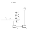
- Figure 7 shows a magneto-optical recording apparatus used to carry out the magneto-optical recording method of the present invention.
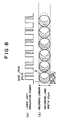
- Figure 8 shows the magneto-optical recording method of the present invention, and particularly the relation between the pulse of light irradiation and the formed domain.
- FIG. 9 and 10 show further embodiments of the present invention.
- the magneto-optical recording film used is GdTbFeCo film which is a rare earth-transition metal thin film.
- Figure 4 shows the temperature characteristic of this film, and particularly shows the relations among magnetization Ms (A/m cc and emu/cc) and coercive force Hc (A/m and (KOe) and temperature.
- the recording film in the present embodiment is ferrimagnetic material thin film having a compensation point temperature of about 80°C and a curie point temperature of about 200°C.
- a recording domain of about 1.0 ⁇ m was prerecorded on such magneto-optical recording film, whereafter overwriting was effected with the pulse width of a laser varied at the same recording laser power.
- Figure 5 shows the relation between the recording pulse width obtained at that time and the residual domain diameter.
- the recording bias magnetic field at that time was about 1591 A/m (20 Oe) in the recording direction.
- the result is divided into three areas (A), (B) and (C), as shown in Figure 5.
- the area (A) in which the recording pulse width is 18 ns or less is an area in which light irradiation energy for erasing is little and the history domain cannot be erased.
- the area (B) in which the recording pulse width is 18-30 ns is an area of recording condition in which the history domain can be completely erased.
- the area (C) in which the recording pulse width is 30 ns or more is an area of recording condition in which a domain can be formed independently of the history domain,
- Figure 6 shows the relation between recording pulse width and recording domain diameter when there is no history recording domain. As is apparent from Figure 6, no domain is formed in an area (D) wherein the recording pulse width is 0-30 ns, and a domain is formed in an area (E) wherein the recording pulse width is 30 ns or more.
- the recording pulse width is set to 18 - 30 ns, there can be brought about a state in which no domain is formed, i.e., an erased state, after overwriting, irrespective of the history state. Also, if the recording pulse width is set to 30 ns or more, a domain will be formed after overwriting, irrespective of the history state, and recording can be effected.
- the overwriting utilizing the movement of the magnetic wall by the effect of the anti-magnetic field in Figures 5 and 6 is an overwriting technique using two phenomena, i.e., the erasing by light irradiation by low energy, and the formation of a domain by light irradiation of high energy.
- the present invention is a magneto-optical recording method utilizing the above-described overwriting system utilizing the movement of the magnetic wall of the formed domain by the anti-magnetic field in the temperature rise and cooling process by laser light irradiation.
- laser light 4 emitted from a laser source 3 is modulated by a recording signal made by a recording signal modulator 2.
- the laser light 4 which has left the laser source 3 passes through a collimator lens 5 and an objective lens 6 and irradiates a magneto-optical recording medium 7.
- a magnetic head 8 provided in opposed relationship with an optical head with the recording medium interposed therebetween is driven by a driving circuit 9, and an extraneous magnetic field is applied to the recording medium.
- the reference numeral 1 designates a control unit for controlling the recording signal modulator 2 and the driving circuit 9.
- Figure 8(a) shows laser light applied to the recording medium, and the laser light is applied with the recording pulse width thereof changed over alternately to 50 ns and 25 ns.
- Figure 8(b) shows recording domains formed by the application of this laser light.
- recording was effected so that as shown in Figure 8, after overwriting, the recording domain length and the unrecorded domain length might be approximately 0.5 ⁇ m and approximately 0.5 ⁇ m, respectively, on a track having a recording land width of 1.0 ⁇ m.
- the recording pulse width of the laser irradiation when the recording domain is formed is 50 ns as shown in Figure 8(a), and as the result, a circular recording domain 1 having a diameter of approximately 1.0 ⁇ m is formed as shown in Figure 8(b). At this time, recording domains corresponding to the recording conditions of the area (C) of Figure 5 are formed.
- the domain width of the domain formed by such recording can be widely recorded up to the full recording land width, and the recording domain length does not decrease with a decrease in the recording domain width. Accordingly, the characteristic of the carrier level to the recording domain length becomes similar to that in the magnetic field modulation system indicated by the dotted curve in Figure 1, and as compared with the prior art, the reduction in the carrier level can be greatly suppressed.
- Figure 9 shows another embodiment of the present invention.
- the control of light energy was effected by keeping the pulse width constant and changing its crest value, instead of changing the pulse width of recording and erasing. That is, as shown in Figure 9(a), laser light of light power P w was applied and immediately after that, laser light of light power P e weaker than the light power P w was applied.
- circular recording domains 1 are formed as shown in Figure 9(b), and circular erasing portions 2 are formed.
- crescent domains are formed and an effect entirely similar to that of the previous embodiment is obtained.
- Figure 10 shows still another embodiment of the present invention.
- This embodiment is a modification of the embodiment of Figure 9, and is an embodiment in which as shown in Figure 10(a), a constant amount of light power P e for erasing is normally applied and light power P w for forming domains is superposed thereon.
- P e constant amount of light power
- P w light power
- the formation and erasing of recording domains are effected as shown in Figure 10(b), and as in the embodiments of Figures 8 and 9, crescent domains are formed. Accordingly, again in this embodiment, there can be obtained an effect entirely similar to that of the aforedescribed two embodiments.
- the magneto-optical recording method of the present invention is a method in which a first recording domain is formed by the application of light of predetermined energy, and after the application of said light, a portion of said first recording domain is erased by the application of light of energy smaller than said light energy to thereby form a crescent second recording domain.
- said first recording domain is formed over the substantially full recording land width.
- control of the light energies of the light irradiation for forming said first recording domain and the light irradiation for effecting said erasing is accomplished by changing the pulse width of the light irradiation.
- control of the light energies of the light irradiation for forming said first recording domain and the light irradiation for effecting said erasing is accomplished by changing the crest value of the pulse of the light irradiation.
- the present invention there can be formed recording domains which are formed by light modulation recording and yet are free of a reduction in carrier level. Accordingly, there can be obtained a good reproduction signal and thus, there can be provided an apparatus of low error rate. There is no possibility of the head crash by a floating magnetic head or the like as is experienced in the magnetic field modulation system, and further any additional device such as a magnetic head is unnecessary and therefore, there can be realized a highly reliable, compact and simple light modulation overwriting apparatus.
Claims (19)
- Procédé d'enregistrement magnéto-optique dans lequel l'enregistrement d'informations sur un milieu (7) d'enregistrement magnéto-optique est effectué par l'application d'une lumière modulée au milieu (7) d'enregistrement, comprenant les étapes dans lesquelles :on applique une impulsion de lumière d'une énergie prédéterminée au milieu (7) d'enregistrement pour former un premier domaine d'enregistrement (1) ;le procédé étant caractérisé en ce qu'il comprend une autre étape dans laquelle :on applique une impulsion de lumière d'une énergie inférieure à ladite énergie prédéterminée après ladite application de l'impulsion de lumière d'énergie prédéterminée afin d'effacer une partie du premier domaine d'enregistrement (1) pour former un domaine d'enregistrement en forme de croissant à l'intérieur du premier domaine d'enregistrement (1).
- Procédé selon la revendication 1, dans lequel ledit premier domaine d'enregistrement (1) est formé par l'application d'une première impulsion de lumière ayant une première largeur d'impulsion au milieu d'enregistrement magnéto-optique (7), et ledit domaine en forme de croissant est formé par l'application d'une seconde impulsion de lumière ayant une seconde largeur d'impulsion différente de la première largeur d'impulsion pour effacer une partie du premier domaine d'enregistrement (1).
- Procédé selon la revendication 2, dans lequel la seconde largeur d'impulsion est inférieure à la première largeur d'impulsion.
- Procédé selon la revendication 3, dans lequel la puissance de la première impulsion de lumière ayant la première largeur d'impulsion est la même que la puissance de la seconde impulsion de lumière ayant la seconde largeur d'impulsion.
- Procédé selon la revendication 1, dans lequel le premier domaine d'enregistrement (1) est formé par l'application d'une première impulsion de lumière ayant une première largeur d'impulsion au milieu d'enregistrement magnéto-optique (7), et le domaine d'enregistrement en forme de croissant est formé par l'application d'une seconde impulsion de lumière d'une seconde largeur d'impulsion, la crête de la seconde impulsion de lumière étant différente de la crête de la première impulsion de lumière, pour effacer une partie du premier domaine d'enregistrement (1).
- Procédé selon la revendication 5, dans lequel la première largeur d'impulsion est la même que la seconde largeur d'impulsion.
- Procédé selon la revendication 5, dans lequel la puissance de la première impulsion de lumière appliquée au support d'enregistrement est plus grande que la puissance de la seconde impulsion de lumière appliquée au milieu d'enregistrement (7).
- Procédé selon la revendication 1, dans lequel le premier domaine d'enregistrement (1) est formé par l'application d'une première impulsion de lumière ayant une largeur d'impulsion prédéterminée au milieu d'enregistrement magnéto-optique (7), et le domaine d'enregistrement ayant la forme d'un croissant est formé par l'application d'une seconde impulsion de lumière ayant une puissance inférieure à celle de la première impulsion de lumière pour effacer une partie du premier domaine d'enregistrement.
- Procédé selon l'une quelconque des revendications précédentes, dans lequel le premier domaine d'enregistrement est formé sur sensiblement toute la largeur d'une plage d'enregistrement sur le milieu d'enregistrement magnéto-optique (7).
- Appareil d'enregistrement magnéto-optique pour enregistrer des informations sur un milieu d'enregistrement (7) en appliquant des impulsions de lumière modulées sur le milieu d'enregistrement, l'appareil comportant des moyens (2, 3) destinés à appliquer une impulsion de lumière d'une énergie prédéterminée au milieu d'enregistrement (7) pour former un premier domaine d'enregistrement (1) ;
l'appareil étant caractérisé en ce qu'il comprend en outre des moyens destinés à appliquer une impulsion de lumière d'énergie inférieure à ladite énergie prédéterminée après l'application de l'impulsion de lumière d'énergie prédéterminée pour former un domaine d'enregistrement en forme de croissant à l'intérieur du premier domaine d'enregistrement (1). - Appareil d'enregistrement magnéto-optique selon la revendication 10, dans lequel lesdits moyens destinés à appliquer une impulsion de lumière d'une première énergie prédéterminée sont agencés pour produire une première impulsion de lumière ayant une première largeur d'impulsion et les moyens destinés à produire une impulsion de lumière d'énergie inférieure sont agencés pour produire une seconde impulsion de lumière ayant une seconde largeur d'impulsion différente de la première largeur d'impulsion.
- Appareil d'enregistrement magnéto-optique selon la revendication 11, dans lequel la seconde largeur d'impulsion est inférieure à la première largeur d'impulsion.
- Appareil d'enregistrement magnéto-optique selon la revendication 12, dans lequel la puissance de la première impulsion de lumière ayant une première largeur d'impulsion est égale à la puissance de la seconde impulsion de lumière ayant la seconde largeur d'impulsion.
- Appareil d'enregistrement magnéto-optique selon la revendication 10, dans lequel les moyens destinés à appliquer une première impulsion de lumière sont agencés pour appliquer une impulsion de lumière ayant une première largeur d'impulsion au support d'enregistrement magnéto-optique (7) et les moyens destinés à appliquer une seconde impulsion de lumière sont agencés pour appliquer une impulsion de lumière ayant une seconde largeur d'impulsion, et une crête qui est différente de celle de l'impulsion de lumière de la première largeur d'impulsion.
- Appareil selon la revendication 14, dans lequel la première largeur d'impulsion est égale à la seconde largeur d'impulsion.
- Appareil selon la revendication 12, dans lequel les moyens destinés à appliquer la première impulsion de lumière sont agencés pour appliquer une impulsion de lumière ayant une puissance qui est supérieure à la puissance de la seconde impulsion de lumière ayant la seconde largeur d'impulsion.
- Appareil selon la revendication 10, dans lequel les moyens destinés à appliquer une seconde impulsion de lumière sont agencés pour appliquer une impulsion de lumière de puissance inférieure.
- Appareil selon l'une quelconque des revendications 10 à 17, dans lequel le premier domaine d'enregistrement (1) est formé sur sensiblement toute la largeur de la plage d'enregistrement sur le support d'enregistrement magnéto-optique (7).
- Support d'enregistrement comportant un milieu d'enregistrement magnéto-optique comprenant plusieurs domaines d'enregistrement magnétiques en forme de croissant présentant chacun la différence entre un premier domaine circulaire (1) et une partie formée par une seconde région circulaire, partiellement chevauchante, d'un diamètre inférieur à celui du premier domaine circulaire et décalée dans la direction de l'enregistrement.
Applications Claiming Priority (2)
| Application Number | Priority Date | Filing Date | Title |
|---|---|---|---|
| JP2278938A JP2838908B2 (ja) | 1990-10-19 | 1990-10-19 | 光磁気記録方法 |
| JP278938/90 | 1990-10-19 |
Publications (3)
| Publication Number | Publication Date |
|---|---|
| EP0481786A2 EP0481786A2 (fr) | 1992-04-22 |
| EP0481786A3 EP0481786A3 (en) | 1992-10-28 |
| EP0481786B1 true EP0481786B1 (fr) | 1997-04-23 |
Family
ID=17604162
Family Applications (1)
| Application Number | Title | Priority Date | Filing Date |
|---|---|---|---|
| EP91309588A Expired - Lifetime EP0481786B1 (fr) | 1990-10-19 | 1991-10-17 | Méthode pour l'enregistrement magnéto-optique |
Country Status (4)
| Country | Link |
|---|---|
| US (1) | US5555236A (fr) |
| EP (1) | EP0481786B1 (fr) |
| JP (1) | JP2838908B2 (fr) |
| DE (1) | DE69125783T2 (fr) |
Families Citing this family (6)
| Publication number | Priority date | Publication date | Assignee | Title |
|---|---|---|---|---|
| JPH06131722A (ja) * | 1992-10-16 | 1994-05-13 | Canon Inc | 光磁気記録媒体およびその記録方法 |
| US5737301A (en) * | 1995-06-01 | 1998-04-07 | Hitachi, Ltd. | Laser control for setting average recording power of "1" equal to average recording power of "0" |
| JPH1131343A (ja) * | 1997-07-08 | 1999-02-02 | Canon Inc | 光磁気記録再生方法及び光磁気記録再生装置と光磁気記録方法 |
| US6987720B2 (en) * | 2000-07-13 | 2006-01-17 | Ricoh Company, Ltd. | Information recording and/or reproducing apparatus, information recording and/or reproducing method, and phase-change recording medium for use in the apparatus and the methods |
| WO2002103692A1 (fr) * | 2001-06-18 | 2002-12-27 | Koninklijke Philips Electronics N.V. | Enregistrement magneto-optique pour lecture amelioree par expansion de domaine |
| KR100925213B1 (ko) * | 2002-06-07 | 2009-11-06 | 엘지전자 주식회사 | 고밀도 멀티 레이어 광디스크와, 그에 따른 광 파워조절방법 |
Family Cites Families (12)
| Publication number | Priority date | Publication date | Assignee | Title |
|---|---|---|---|---|
| JPS57186248A (en) * | 1981-05-09 | 1982-11-16 | Ricoh Co Ltd | Vertically thermomagnetic recording and reproducing system |
| JP2521908B2 (ja) * | 1985-06-11 | 1996-08-07 | 株式会社ニコン | オ―バ―ライト可能な光磁気記録方法、それに使用される光磁気記録装置及び光磁気記録媒体、並びに変調方法、変調装置及び光磁気記録媒体 |
| US4843604A (en) * | 1985-10-16 | 1989-06-27 | Sharp Kabushiki Kaisha | Beam controller for magneto-optical disc memory system |
| US4982389A (en) * | 1987-01-30 | 1991-01-01 | Hitachi, Ltd. | Magneto-optical recorder with compensation for variation in applied magnetic field intensity on a recording medium |
| JPS6430042A (en) * | 1987-07-24 | 1989-01-31 | Matsushita Electric Industrial Co Ltd | Magneto-optical memory device |
| US5043960A (en) * | 1987-09-25 | 1991-08-27 | Hitachi, Ltd. | Overwritable magneto-optic recording and reproducing apparatus |
| JP2912373B2 (ja) * | 1988-04-20 | 1999-06-28 | シャープ株式会社 | 光磁気記録再生装置 |
| JP2655682B2 (ja) * | 1988-06-08 | 1997-09-24 | 株式会社日立製作所 | 光磁気情報記録再生装置 |
| JPH0233749A (ja) * | 1988-07-22 | 1990-02-02 | Hitachi Ltd | 光磁気記録方式 |
| NL8900362A (nl) * | 1989-02-15 | 1990-09-03 | Philips Nv | Werkwijze en inrichting voor het inschrijven en uitlezen van een magneto-optische registratiedrager. |
| JP2846342B2 (ja) * | 1989-06-07 | 1999-01-13 | 株式会社日立製作所 | 高密度光再生装置 |
| NL8902293A (nl) * | 1989-09-14 | 1991-04-02 | Philips Nv | Werkwijze en inrichting voor het inschrijven en uitlezen van een magneto-optische registratiedrager. |
-
1990
- 1990-10-19 JP JP2278938A patent/JP2838908B2/ja not_active Expired - Fee Related
-
1991
- 1991-10-17 EP EP91309588A patent/EP0481786B1/fr not_active Expired - Lifetime
- 1991-10-17 DE DE69125783T patent/DE69125783T2/de not_active Expired - Fee Related
-
1995
- 1995-04-25 US US08/428,000 patent/US5555236A/en not_active Expired - Lifetime
Also Published As
| Publication number | Publication date |
|---|---|
| US5555236A (en) | 1996-09-10 |
| DE69125783T2 (de) | 1997-10-09 |
| EP0481786A2 (fr) | 1992-04-22 |
| JPH04155637A (ja) | 1992-05-28 |
| EP0481786A3 (en) | 1992-10-28 |
| DE69125783D1 (de) | 1997-05-28 |
| JP2838908B2 (ja) | 1998-12-16 |
Similar Documents
| Publication | Publication Date | Title |
|---|---|---|
| US5323374A (en) | Method of magneto-optical recording | |
| EP0481786B1 (fr) | Méthode pour l'enregistrement magnéto-optique | |
| EP0593249B1 (fr) | Méthode et système d'enregistrement d'information magnéto-optique | |
| JP2839498B2 (ja) | 光ディスク媒体 | |
| KR0143541B1 (ko) | 광자기 기록 방법 | |
| JP2642639B2 (ja) | 光磁気記録方法 | |
| US5093817A (en) | Method and apparatus for recording information on an opto-magnetic recording medium by applying a modulated light beam while applying a magnetic field alternating with a constant period | |
| EP0471527B1 (fr) | Procédé et système de reproduction d'information d'un milieu d'enregistrement magnétique | |
| JP3185932B2 (ja) | 光磁気記録再生方法ならびに光磁気記録再生装置 | |
| JP2804806B2 (ja) | 情報の記録方法 | |
| US5814418A (en) | Magneto-optical recording medium and method for reading out information from the same | |
| US5781513A (en) | Magnetic-field modulation recording method and device for preventing residual information from remaining after overwriting | |
| US5757736A (en) | Method of and apparatus for recording information to magneto optical disc having plural recording layers | |
| KR100292604B1 (ko) | 오버라이트가능한광기록매체및그의기록방법 | |
| EP0595626B1 (fr) | Méthode et appareil de détermination de la condition d'enregistrement lors de la reécriture sur disque magnétooptique, par la méthode d'interruption du chauffage et la méthode des trains d'impulsions ainsi qu'appareil et méthode d'enregistrement | |
| US5574703A (en) | Magneto-optical method and apparatus for recording/reproducing data | |
| EP0611120B1 (fr) | Méthode d'enregistrement magnéto-optique capable de sur-écrire | |
| KR0119791Y1 (ko) | 오버 라이트용 광자기 디스크 드라이브 | |
| JP2749877B2 (ja) | 情報記録装置 | |
| JPH02306445A (ja) | 光磁気記録媒体 | |
| JPH05290435A (ja) | 光磁気記録方式 | |
| JPH05298771A (ja) | 光磁気記録方式 | |
| EP0780841A2 (fr) | Milieu d'enregistrement magnéto-optique utilisant un matériau magnétique à transformation de phase et méthode d'enregistrement utilisant le milieu | |
| JPH04263149A (ja) | 光磁気記録方式 | |
| JPH08147790A (ja) | 光磁気記録方法及び光磁気記録装置 |
Legal Events
| Date | Code | Title | Description |
|---|---|---|---|
| PUAI | Public reference made under article 153(3) epc to a published international application that has entered the european phase |
Free format text: ORIGINAL CODE: 0009012 |
|
| AK | Designated contracting states |
Kind code of ref document: A2 Designated state(s): DE FR GB IT NL |
|
| PUAL | Search report despatched |
Free format text: ORIGINAL CODE: 0009013 |
|
| AK | Designated contracting states |
Kind code of ref document: A3 Designated state(s): DE FR GB IT NL |
|
| 17P | Request for examination filed |
Effective date: 19930310 |
|
| 17Q | First examination report despatched |
Effective date: 19950412 |
|
| GRAG | Despatch of communication of intention to grant |
Free format text: ORIGINAL CODE: EPIDOS AGRA |
|
| GRAH | Despatch of communication of intention to grant a patent |
Free format text: ORIGINAL CODE: EPIDOS IGRA |
|
| GRAH | Despatch of communication of intention to grant a patent |
Free format text: ORIGINAL CODE: EPIDOS IGRA |
|
| GRAA | (expected) grant |
Free format text: ORIGINAL CODE: 0009210 |
|
| AK | Designated contracting states |
Kind code of ref document: B1 Designated state(s): DE FR GB IT NL |
|
| REF | Corresponds to: |
Ref document number: 69125783 Country of ref document: DE Date of ref document: 19970528 |
|
| ET | Fr: translation filed | ||
| PLBE | No opposition filed within time limit |
Free format text: ORIGINAL CODE: 0009261 |
|
| STAA | Information on the status of an ep patent application or granted ep patent |
Free format text: STATUS: NO OPPOSITION FILED WITHIN TIME LIMIT |
|
| 26N | No opposition filed | ||
| REG | Reference to a national code |
Ref country code: GB Ref legal event code: IF02 |
|
| PGFP | Annual fee paid to national office [announced via postgrant information from national office to epo] |
Ref country code: NL Payment date: 20081017 Year of fee payment: 18 |
|
| PGFP | Annual fee paid to national office [announced via postgrant information from national office to epo] |
Ref country code: DE Payment date: 20081031 Year of fee payment: 18 |
|
| PGFP | Annual fee paid to national office [announced via postgrant information from national office to epo] |
Ref country code: IT Payment date: 20081020 Year of fee payment: 18 |
|
| PGFP | Annual fee paid to national office [announced via postgrant information from national office to epo] |
Ref country code: FR Payment date: 20081024 Year of fee payment: 18 |
|
| PGFP | Annual fee paid to national office [announced via postgrant information from national office to epo] |
Ref country code: GB Payment date: 20081029 Year of fee payment: 18 |
|
| REG | Reference to a national code |
Ref country code: NL Ref legal event code: V1 Effective date: 20100501 |
|
| REG | Reference to a national code |
Ref country code: FR Ref legal event code: ST Effective date: 20100630 |
|
| PG25 | Lapsed in a contracting state [announced via postgrant information from national office to epo] |
Ref country code: FR Free format text: LAPSE BECAUSE OF NON-PAYMENT OF DUE FEES Effective date: 20091102 Ref country code: DE Free format text: LAPSE BECAUSE OF NON-PAYMENT OF DUE FEES Effective date: 20100501 Ref country code: NL Free format text: LAPSE BECAUSE OF NON-PAYMENT OF DUE FEES Effective date: 20100501 |
|
| PG25 | Lapsed in a contracting state [announced via postgrant information from national office to epo] |
Ref country code: GB Free format text: LAPSE BECAUSE OF NON-PAYMENT OF DUE FEES Effective date: 20091017 |
|
| PG25 | Lapsed in a contracting state [announced via postgrant information from national office to epo] |
Ref country code: IT Free format text: LAPSE BECAUSE OF NON-PAYMENT OF DUE FEES Effective date: 20091017 |