EP0481820B1 - Système pour la culture en continu de cellules à haute densité - Google Patents
Système pour la culture en continu de cellules à haute densité Download PDFInfo
- Publication number
- EP0481820B1 EP0481820B1 EP91309665A EP91309665A EP0481820B1 EP 0481820 B1 EP0481820 B1 EP 0481820B1 EP 91309665 A EP91309665 A EP 91309665A EP 91309665 A EP91309665 A EP 91309665A EP 0481820 B1 EP0481820 B1 EP 0481820B1
- Authority
- EP
- European Patent Office
- Prior art keywords
- plates
- tissue culture
- plate assembly
- culture plate
- chambers
- Prior art date
- Legal status (The legal status is an assumption and is not a legal conclusion. Google has not performed a legal analysis and makes no representation as to the accuracy of the status listed.)
- Expired - Lifetime
Links
- 238000004113 cell culture Methods 0.000 title description 12
- 239000012530 fluid Substances 0.000 claims description 41
- 230000012010 growth Effects 0.000 claims description 38
- 210000002105 tongue Anatomy 0.000 claims description 7
- 238000007789 sealing Methods 0.000 claims description 3
- 230000005465 channeling Effects 0.000 claims description 2
- 210000004027 cell Anatomy 0.000 description 21
- 239000002609 medium Substances 0.000 description 18
- 230000010261 cell growth Effects 0.000 description 9
- 239000000463 material Substances 0.000 description 9
- 238000004519 manufacturing process Methods 0.000 description 7
- 235000015097 nutrients Nutrition 0.000 description 6
- 238000004891 communication Methods 0.000 description 5
- 238000000034 method Methods 0.000 description 5
- 239000000047 product Substances 0.000 description 5
- 238000003466 welding Methods 0.000 description 5
- 238000010276 construction Methods 0.000 description 4
- 238000012258 culturing Methods 0.000 description 4
- 238000009826 distribution Methods 0.000 description 4
- 230000002093 peripheral effect Effects 0.000 description 4
- 238000011282 treatment Methods 0.000 description 4
- 230000001788 irregular Effects 0.000 description 3
- 230000013011 mating Effects 0.000 description 3
- KAKZBPTYRLMSJV-UHFFFAOYSA-N Butadiene Chemical compound C=CC=C KAKZBPTYRLMSJV-UHFFFAOYSA-N 0.000 description 2
- 238000013459 approach Methods 0.000 description 2
- 238000000465 moulding Methods 0.000 description 2
- 231100000252 nontoxic Toxicity 0.000 description 2
- 230000003000 nontoxic effect Effects 0.000 description 2
- 238000004382 potting Methods 0.000 description 2
- 230000001737 promoting effect Effects 0.000 description 2
- 239000002904 solvent Substances 0.000 description 2
- 102000008186 Collagen Human genes 0.000 description 1
- 108010035532 Collagen Proteins 0.000 description 1
- 102000016359 Fibronectins Human genes 0.000 description 1
- 108010067306 Fibronectins Proteins 0.000 description 1
- 102000014150 Interferons Human genes 0.000 description 1
- 108010050904 Interferons Proteins 0.000 description 1
- 239000004793 Polystyrene Substances 0.000 description 1
- 241000700605 Viruses Species 0.000 description 1
- 229920001400 block copolymer Polymers 0.000 description 1
- 125000003178 carboxy group Chemical group [H]OC(*)=O 0.000 description 1
- 230000030833 cell death Effects 0.000 description 1
- 230000001413 cellular effect Effects 0.000 description 1
- 229920001436 collagen Polymers 0.000 description 1
- 239000003636 conditioned culture medium Substances 0.000 description 1
- 238000011109 contamination Methods 0.000 description 1
- 238000007796 conventional method Methods 0.000 description 1
- 210000004748 cultured cell Anatomy 0.000 description 1
- 239000003814 drug Substances 0.000 description 1
- 230000009977 dual effect Effects 0.000 description 1
- 230000007613 environmental effect Effects 0.000 description 1
- 239000012467 final product Substances 0.000 description 1
- 239000012737 fresh medium Substances 0.000 description 1
- 239000011521 glass Substances 0.000 description 1
- 239000003292 glue Substances 0.000 description 1
- 238000003306 harvesting Methods 0.000 description 1
- 238000002347 injection Methods 0.000 description 1
- 239000007924 injection Substances 0.000 description 1
- 229940079322 interferon Drugs 0.000 description 1
- 238000011031 large-scale manufacturing process Methods 0.000 description 1
- 238000012544 monitoring process Methods 0.000 description 1
- 239000004033 plastic Substances 0.000 description 1
- 229920002223 polystyrene Polymers 0.000 description 1
- 230000001902 propagating effect Effects 0.000 description 1
- 238000011084 recovery Methods 0.000 description 1
- 210000001364 upper extremity Anatomy 0.000 description 1
- 229960005486 vaccine Drugs 0.000 description 1
- 239000002699 waste material Substances 0.000 description 1
Images



Classifications
-
- C—CHEMISTRY; METALLURGY
- C12—BIOCHEMISTRY; BEER; SPIRITS; WINE; VINEGAR; MICROBIOLOGY; ENZYMOLOGY; MUTATION OR GENETIC ENGINEERING
- C12M—APPARATUS FOR ENZYMOLOGY OR MICROBIOLOGY; APPARATUS FOR CULTURING MICROORGANISMS FOR PRODUCING BIOMASS, FOR GROWING CELLS OR FOR OBTAINING FERMENTATION OR METABOLIC PRODUCTS, i.e. BIOREACTORS OR FERMENTERS
- C12M23/00—Constructional details, e.g. recesses, hinges
- C12M23/34—Internal compartments or partitions
-
- C—CHEMISTRY; METALLURGY
- C12—BIOCHEMISTRY; BEER; SPIRITS; WINE; VINEGAR; MICROBIOLOGY; ENZYMOLOGY; MUTATION OR GENETIC ENGINEERING
- C12M—APPARATUS FOR ENZYMOLOGY OR MICROBIOLOGY; APPARATUS FOR CULTURING MICROORGANISMS FOR PRODUCING BIOMASS, FOR GROWING CELLS OR FOR OBTAINING FERMENTATION OR METABOLIC PRODUCTS, i.e. BIOREACTORS OR FERMENTERS
- C12M23/00—Constructional details, e.g. recesses, hinges
- C12M23/02—Form or structure of the vessel
- C12M23/04—Flat or tray type, drawers
Definitions
- This invention relates to a method and apparatus for the culture of cells and more particularly relates to an improvement of the apparatus disclosed in co-pending international application WO-A-92/05243.
- U.S. Patent No. 4,307,193 discloses a method for producing interferon from tissue culture cells using a propagating apparatus having a plurality of spaced-apart flat plates, which can be interconnected to allow medium and gas to pass between successive plates.
- the cell-culturing devices of the prior art all have various drawbacks, including the need for excessive amounts of medium, the inability to provide a continuous flow of nutrients to all cell-growth surfaces, the need for labor-intensive monitoring and care of the growing cells and the inability to operate continuously.
- An object of this invention is to provide a cell culture device in which cells may be grown to a high density relative to the amount of nutrient medium contained within the system.
- Another object of this invention is to provide a cell culture assembly having a plurality of growth chambers for receiving medium flow substantially equally.
- Another object of this invention is to provide a cell culture assembly having a plurality of growth chambers, which has reduced manufacturing costs as compared to the system shown in WO-A-92/05243, supra.
- Yet another object of this invention is to provide a more effective seal for each of the chambers of the cell culture assembly shown in WO-A-92/05243, supra.
- tissue culture plate assembly comprising:
- the invention may provide a cell culture assembly that allows for the automatic, continuous addition of nutrient medium and the removal of conditioned medium containing the products and waste formed by the cells.
- the invention may provide a cell culture assembly and system in which the cellular environmental condition may be continuously monitored, with any departures from the desired conditions being automatically corrected or alarmed.
- the invention may be arranged to provide a continuous flow system to facilitate a desirable chemostatic environment for the cells and to facilitate optimal yield and harvesting ability for cell products such as biochemicals, vaccine virus, and pharmaceuticals.
- the invention provides a continous cell culturing device having an array of growth chambers defining a very large surface area for high-density cell growth in a small volume.
- the device is constructed and arranged to permit directional flow through the growth chambers, the flow being continuous and capable of reaching all growth surfaces within each chamber. Adequate flow in each chamber is accomplished by providing each chamber with a fluid restriction port, these ports acting to control the flow and distribution of fluid into each of the growth chambers.
- the cell culturing device includes an array of cell growth chambers defined by the spaces between a plurality of stacked plates.
- An inlet conduit provides a source of nutrient medium to a manifold in fluid communication with the cell growth chambers via the fluid restriction ports.
- the sum of the cross-sectional areas of the narrowest region of the fluid restriction ports is less than the cross-sectional area of the inlet conduit, thereby ensuring a pressure drop across each of the fluid restriction ports and adequate flow of fluid through each growth chamber.
- the fluid restriction ports and growth chambers are constructed and arranged to promote the distribution and continuous directional flow of fluid medium to all growth surfaces with a minimum of turbulence. This may be accomplished by providing growth chambers that are essentially square boxes, with an inlet restriction port and an outlet restriction port at opposing corners of the box.
- the fluid restriction ports may have a constricted intermediate section, and the corners may have curved surfaces to promote fluid distribution and nonturbulent flow. Ribs may be provided between opposing faces of the plates to provide structural support and further to direct fluid flow.
- the invention thus can provide a closed sterile system for the culture of cells and prevents both exposure of personnel to the cells and their products and the contamination of the culture from the outside environment. Growth conditions may be sensed automatically, with nutrients added and cell-products removed responsive to the sensed condition.
- the device can be supplied economically and can be manufactured in large scale production.
- the stacked plates are sealed by a continuous frame that engages the edges of all the plates to seal the chambers.
- the frame can be molded about the plates as a single step and avoids the handling of the individual plates to separately seal the individual chambers. Because the assembly may have as many as twenty-five or fifty chambers formed by a corresponding number of plates stacked one upon another, this manufacturing procedure results in very substantial cost savings.
- the cell culture device of the present invention embodiment includes an array of growth chambers enclosed within a vessel.
- the growth chambers provide a large surface area for cell growth.
- the vessel 10 is a substantially square box with square, molded top 12 and base 13, and vertical molded sidewalls 14 sealed along the edges to provide a fluid-tight arrangement for housing the growth chambers.
- the inlet conduit 16 provides fluid access to the interior space of the vessel 10, and the outlet conduit 18 provides fluid egress from the interior space of the vessel 10.
- the outlet conduit 18 may extend through the base 13, rather than through the top 12 as shown.
- the inlet conduit 16 is in axial alignment and in fluid communication with an inlet manifold 20 extending transversely through the interior space of the vessel 10 at the corner.
- Inlet restriction ports 22 provide fluid communication between the manifold 20 and a plurality of cell growth chambers 24 located within vessel 10, which chambers 24 are defined by an array of stacked plates 26.
- At the corner of the vessel opposite the inlet manifold 20 is an outlet manifold 28 in fluid communication with the outlet conduit 18.
- Each growth chamber 24 is in fluid communication with the outlet manifold 28 via an outlet fluid restriction port 23.
- the inlet and outlet manifold arrangements in accordance with one embodiment are mirror images of one another and, therefore, the flow characteristics will be the same whether the fluid medium is flowing from the inlet to the outlet ends, or vice versa.
- the relative size of the restriction ports 22,23 and conduits 16,18 comprise one aspect of the invention.
- a pressure drop must be created across the flow restriction port controlling flow within each chamber.
- the sizes of the restriction ports controlling flow are selected such that the sum of the cross-sectional areas of the narrowest portion of these restriction ports is equal to or preferably less than the cross-sectional area of the inlet conduit.
- the sum of these cross-sectional areas also is equal to or less than the cross-sectional area of the outlet conduit.
- no particular growth chamber will be favored due to its location, and all growth chambers will receive fluid medium based principally upon the particular size of the fluid restriction port controlling flow in that chamber.
- the fluid restriction ports are uniformly dimensioned so that each growth chamber will receive fluid medium at an identical flow rate.
- FIGS. 2-4 there are flow restriction ports at both the inlet and the outlet end of the growth chambers.
- the smaller of the inlet and outlet restriction ports will control the flow through a particular growth chamber, without regard to its location at the inlet or outlet end.
- it is the sum of the cross-sectional areas of the smaller of the inlet and outlet restriction ports for each chamber that should be less than the cross-sectional area of the conduits. If a pair of inlet and outlet restriction ports are uniformly dimensioned and have the same cross-sectional area at their narrowest portion, then in calculating the sum of the cross-sectional areas as described above, only one cross-sectional area is included.
- the plates 26 are stacked to form the growth chambers.
- the plates are spaced 1 mm apart or greater.
- the plates may be spaced closer to one another, air bubbles tend tb become trapped between the plates and interrupt the even flow of medium when spaced less than 1 mm apart.
- the surfaces of the plates may be roughened, corrugated, convoluted or otherwise irregular to increase their surface area and the number of cells capable of growing on a given plate. If irregular, the 1 mm spacing between the plates should be between the facing peaks of irregular surfaces.
- the surfaces of the plates also may be surface treated in a variety of different ways to promote cell growth. Typical treatments include carboxyl group treatments, collagen treatments, fibronectin treatments or feeder cell layers.
- the plates according to the preferred embodiment were molded from K-resinTM ⁇ , a block co-polymer of polystyrene and butadiene, sold by Phillips Chemical Co., Bartlesville, OK, 74004.
- Suitable plate materials include styrenic materials or materials such as polymethyl pantene.
- the plate may be of virtually any material that is sufficiently strong, nontoxic, biocompatible, and otherwise suitable for tissue culture.
- Each plate 26 has an upper surface 30 bounded by a peripheral wall 32 (Fig. 3).
- the inside facing surface 34 of wall 32 along with the plate upper surface 30 define the side walls and floor of a growth chamber 24.
- the top edge 35 of wall 32 mates and seals with the lower surface 36 of the adjacent plate to define a growth chamber, the ceiling of the chamber being defined by the lower surface 36 of the adjacent plate.
- the wall 32 is provided on its top edge 35 with a groove 33 for receiving a mating ridge 37 on the bottom surface of an adjacent plate. The mating ridge 37 and groove 33 align the stacked plates.
- each plate 26 is solidly filled-in to a thickness equal to the height of the peripheral wall 32.
- the filled corners add support to the assembled structure.
- the filled corners further reduce the potential for fluid turbulence and "dead spots,” as will be explained more fully below.
- Each plate 26 has a bore at diagonally-opposed, filled corners 40.
- the bores 42,44 of the stacked plates 26 are axially aligned and form the inlet and outlet manifolds 20,28, respectively.
- a passage 48 extends from each bore 42,44 through the filled corners 40 to the interior space defined by the side walls and floor of each plate 26.
- These passages in the assembled vessel form the fluid restriction ports 22, 23 providing fluid access between the manifolds 20,28 and the growth chambers 24.
- Each passage has a floor defined by a portion of the upper surface 30 of the plate 26 and sidewalls 49 formed integrally as part of the corners 40.
- the height of each passage equals the height of the peripheral wall 32.
- the fluid restriction ports 22, 23 are formed when the flat bottom surface of an opposing plate 26 is stacked to seal the open upper extremity of the passage 48.
- the particular shape of the fluid restriction port in the preferred embodiment includes a narrowed internal portion, as at constriction 50.
- the width of the flow restriction port 22 increases continuously and substantially from constriction 50 in a direction toward the growth chamber 24. This arrangement causes medium entering the growth chamber to flare-out and be evenly dispersed in a fan pattern into the growth chamber space, promoting nutrient supply and even fluid flow across the entire growth surface. This arrangement also reduces turbulence, especially at and around the restriction ports 22.
- the width of the flow restriction port increases linearly while the height remaining constant.
- a port shaped as a second or third order venturi would provide for continuous, gradual change in velocity, thereby further promoting nonturbulent flow.
- the nonturbulent and directional flow pattern is further facilitated by the filled corners 38 and by flow-guiding ribs 46.
- the corners if not filled, would define areas remote from the direction of flow, which in turn would result in turbulence and "dead spots," that is, areas within the growth chamber which do not receive a continuous and directional flow of fresh media so as to cause cell death.
- the filled corners provide a baffle which acts to channel flow continuously in the direction of the outlet ports.
- the ribs 46 provide a dual function. They serve to provide structural support to each plate maintaining the plates at the proper spacing, even when draining the device under a vacuum, and also may be positioned to channel flow continuously in a direction toward the outlet ports.
- each plate is welded to an adjacent plate by ultrasonic welding.
- any method of fabrication such as solvent welding, RF welding, potting, glue or even gaskets would be acceptable, so long as the final product has sufficient strength and is nontoxic to cultured cells.
- the device first is seeded with cells. Then, fluid media is supplied to the attached cells as follows. Fluid medium is introduced into inlet manifold 20 via inlet conduit 16. The fluid medium then passes through the various flow restriction ports 22 into the associated growth chambers 24. Because of the overall construction of the flow restriction ports and the growth chambers, flow is distributed continuously and thoroughly to all surfaces of the growth chamber 24, the fluid medium always moving generally in a direction toward the outlet flow restrictors 23. The medium then passes through the outlet flow restrictors 23, into the outlet manifold 28 and then out of the device via the outlet conduit 18.
- restriction ports per growth chamber. It is, of course, possible to have many flow restrictors on the inlet or the outlet side.
- One inlet and one outlet restriction port may be preferred as they facilitate manufacture, lessen turbulence, and reduce the lack of cell growth normally found at and very close to the flow restriction ports.
- FIGS. 5-13 includes only the inlet constrictions ports.
- the sum of the cross-sectional areas of the flow restriction ports be less than or equal to the cross-sectional area of the outlet conduit. Otherwise, the outlet conduit will set up a back-pressure which may result in preferential flow through one or more growth chambers.
- FIG. 5 another embodiment of a cell culturing assembly is shown that functionally is the same as the embodiment shown in FIG. 1.
- the assembly differs from that of FIG. 1 in the manner in which the array of plates are held together.
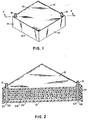
- the assembly 200 shown in FIG. 5 includes inlet and outlet conduits 202 and 204 respectively, a stack of plates 206 and a frame 208 that holds the stack of plates together and hermetically seals the stack of chambers formed between them.
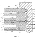
- FIG. 6 only a few of the stack of plates are shown sealed within the frame 208, but it should be appreciated that as many as 25 or 50 plates may be stacked one upon another to form a corresponding number of chambers.
- FIGS. 7-13 one plate 212 that may be used in the stack of FIG. 6 is shown but it is to be understood that other plates such as shown in FIGS. 3 and 4 may be used instead.
- the frame 208 is not limited to just one plate configuration.
- inlet and outlet ports 218 and 220 are provided which correspond to the ports 42 an 44 in the embodiment of FIGS. 3 and 4.
- a thickened rim 222 extends about the four sides of the plate from each surface thereof and surrounds the thin major portion 224 of the plate (see FIGS. 7-9.
- the rim 222 is spaced inwardly from the outer edge 226 of the plate to define a tongue 228 whose function is described below.
- the two surfaces of the plates are substantially identical except for aligning risks in two corners as described below.
- the ports 218 and 220 extend through the thin major portion 224 of the plate, and a pair of V-shaped ribs 230 and 232 disposed on each side of port 218 define a restricted flow path 234 between the adjacent apexes of the V-shaped ribs 230 and 232. No restricted passage is formed adjacent the outlet port 220 that corresponds to the restricted passage 234.
- diagonal ribs 244 and 246, respectively, connect adjacent portions of the rim 222 and define baffles in the chambers so as to eliminate the so called “dead spots" in the corners of the chambers remote from the flow path between the inlet and outlet ducts 218 and 220.
- These ribs essentially perform the same function as the fill at the opposed corners in FIGS. 3 and 4.
- FIGS. 7 and 8 the top and bottom surfaces of the plate 212 are shown, and it is evident from them that the two surfaces of the plates as thus described are essentially identical. Therefore, when two identical plates are placed face to face, the rims 222 stack one upon another as shown in FIG.
- the ribs 230, 232, 244 and 246 engage one another to form walls that in part define the growing chambers between the plates.
- the transversely extending ribs 248 that correspond to the ribs 46 in the embodiment of FIGS. 3 and 4 register with one another to direct flow through the chamber.
- ribs 250 and 252 are provided on one face of the plate while corresponding troughs 253 and 254 are formed on the opposite face thereof.
- Cross-sections of the ribs and troughs are shown in FIGS. 12 and 13. It will be noted in the cross-sectional views that the troughs are slightly longer than the ribs so as to assist in centering the plates one upon another.
- the ribs 250 and 252 and troughs 253 and 254 at the opposite corners are disposed at an angle to one another, the troughs and ribs prevent the plates from being stacked in any way but with inlet and outlet ports 218 and 220 of each plate properly aligned at the same corners of the stack. Moreover, the ribs and troughs will serve to hold several plates in the precise alignment with one another before the frame 208 is molded about them.
- no special frame is illustrated for holding the array of plates together and hermetically sealing the chambers, and various methods are suggested for assembling the array of plates, such as ultrasonic welding, solvent welding, potting etc.
- the array of plates are held together by frame 208.
- Very substantial savings in manufacturing costs are derived from this system as well as a better seal for each chamber 211 and an aesthetically superior product is achieved as compared to the vessel manufactured by the other techniques described.
- the frame is molded by placing the stack of plates in a tool cavity and injecting the styrenic material from which the frame is made into the cavity to form it. It will be noted in FIGS.
- the outer face of the topmost plate in the stack does not have the same configuration as the inner face.
- the inner face is identical to the lower faces of the plates below to form a chamber 211.
- only the top face of the lower plate (not shown) is configured to form a chamber 211.
- the frame may be made, it will be appreciated that other materials may be used as well so long as they are compatible with the function performed by the assembly.
- the frame could be injection molded from a rubber-like styrenic material which would provide physical protection for the assembly if it is dropped or otherwise subject to a sharp impact.
- the plates may typically be approximately 58 cm 2 (9 inches square), and a very substantial number of plates may be used in a single assembly to form as many as 25 or 50 chambers.
- the wall thickness of the frame measured to the outer edges of the tongues may be approximately 0.238 cm (3/32 inch) and the outer flange 270 of the frame over the outer surfaces of the end plates as shown in FIG. 10 may be approximately 0.476 cm 2 (3/16 inch). Because the frame is continuous, it permanently and securely bonds the stack together so that the plates cannot accidentally separate nor can any leakage occur from the system so long as the bonds between the frame and the outer surfaces of the end plates are secure.
Landscapes
- Health & Medical Sciences (AREA)
- Organic Chemistry (AREA)
- Life Sciences & Earth Sciences (AREA)
- Engineering & Computer Science (AREA)
- Bioinformatics & Cheminformatics (AREA)
- Chemical & Material Sciences (AREA)
- Zoology (AREA)
- Wood Science & Technology (AREA)
- Sustainable Development (AREA)
- Microbiology (AREA)
- Biotechnology (AREA)
- Biomedical Technology (AREA)
- Biochemistry (AREA)
- General Engineering & Computer Science (AREA)
- General Health & Medical Sciences (AREA)
- Genetics & Genomics (AREA)
- Clinical Laboratory Science (AREA)
- Apparatus Associated With Microorganisms And Enzymes (AREA)
Claims (14)
- Ensemble de plaques de culture de tissus (200) comprenant :une pluralité de plaques (212) empilées les unes sur les autres avec des plaques adjacentes définissant des chambres de croissance (211) entre elles, les plaques présentant des bords (226) qui sont alignés les uns par rapport aux autres dans la pile (206),des tubes d'entrée et de sortie (202 et 204) reliés à la pile afin de canaliser le fluide en direction de et à partir des chambres (211) dans lesquelles chacune desdites plaques (212) présente des conduits d'entrée et de sortie (218 et 220) qui communiquent avec les tubes d'entrée et de sortie (202 et 204) afin de diriger le fluide à travers les chambres (211),et un châssis (208) qui enclôt les bords de toutes les plaques, scellant les chambres (211) de façon étanche et verrouillant ensemble, d'une manière mécanique, les plaques empilées (212).
- Ensemble de plaques de culture de tissus (200) défini dans la revendication 1, dans lequel le châssis (208) est moulé comme structure en un seul bloc autour de tous les bords de toutes les plaques (212).
- Ensemble de plaques de culture de tissus (200) défini dans les revendications 1 ou 2, dans lequel les plaques (212) de la pile sont identiques les unes aux autres.
- Ensemble de plaques de culture de tissus (200) défini dans l'une quelconque des revendications 1 à 3, dans lequel chacune des plaques (212) présente un rebord (222) adjacent au bord (226) qui s'étend autour de la périphérie de celui-ci, les rebords (222) de plaques adjacentes étant empilés les uns sur les autres et formant des parois latérales pour les chambres (211).
- Ensemble de plaques de culture de tissus (200) défini dans l'une quelconque des revendications 1 à 4, dans lequel des languettes (228) sont formées dans les bords (226) des plaques, les languettes (228) des plaques adjacentes (212) de la pile (206) formant des cavités (260) entre celles-ci, ledit châssis (208) remplissant les cavités entre les languettes (228) et liant, de préférence, les plaques (212) ensemble.
- Ensemble de plaques de culture de tissus (200) défini dans l'une quelconque des revendications précédentes, comportant en outre des passages (234) limités formés dans chacune desdites plaques et reliant le conduit d'entrée (218) aux chambres (211) de chaque côté de chacune desdites plaques (212).
- Ensemble de plaques de culture de tissus (200) défini dans la revendication 6, comportant en outre des nervures (230 et 232) formées dans une plaque (212) adjacente au conduit d'entrée (218) afin de définir les passages limités (234)
- Ensemble de plaques de culture de tissus (200) défini dans l'une quelconque des revendications 1 à 7, comportant en outre des nervures d'empilage (250 et 252) et des rainures (253 et 254) sur des faces opposées de chacune des plaques identiques (212) afin d'aligner les plaques (212) les unes avec les autres dans une relation choisie préalablement.
- Ensemble de plaques de culture de tissus (200) défini dans l'une quelconque des revendications précédentes, dans lequel les chambres (211) ont au moins 1 mm d'épaisseur.
- Ensemble de plaques de culture de tissus (200) défini dans l'une quelconque des revendications précédentes, dans lequel les plaques (211) sont sensiblement carrées.
- Ensemble de plaques de culture de tissus (200) défini dans l'une quelconque des revendications précédentes, dans lequel des nervures de support (230, 232, 244 et 246) séparent des plaques adjacentes (212) dans la chambre (211).
- Ensemble de plaques de culture de tissus (200) défini dans les revendications 1 ou 2, dans lequel des saillies (228) sont formées dans les bords (226) des plaques (212), les saillies (228) des plaques adjacentes (212) dans la pile (206) formant des cavités (260) entre celles-ci, ledit châssis (208) remplissant les cavités (260) entre les saillies (228) et liant les plaques (212) ensemble.
- Ensemble de plaques de culture de tissus (200) défini dans l'une quelconque des revendications précédentes, dans lequel le châssis (208) est en contact avec tous les bords (226) de chaque plaque (212).
- Ensemble de plaques de culture de tissus (200) défini dans l'une quelconque des revendications précédentes, comprenant au moins 25 plaques (212).
Applications Claiming Priority (2)
| Application Number | Priority Date | Filing Date | Title |
|---|---|---|---|
| US60019590A | 1990-10-18 | 1990-10-18 | |
| US600195 | 1996-02-12 |
Publications (3)
| Publication Number | Publication Date |
|---|---|
| EP0481820A2 EP0481820A2 (fr) | 1992-04-22 |
| EP0481820A3 EP0481820A3 (en) | 1992-06-10 |
| EP0481820B1 true EP0481820B1 (fr) | 1996-12-18 |
Family
ID=24402672
Family Applications (1)
| Application Number | Title | Priority Date | Filing Date |
|---|---|---|---|
| EP91309665A Expired - Lifetime EP0481820B1 (fr) | 1990-10-18 | 1991-10-18 | Système pour la culture en continu de cellules à haute densité |
Country Status (3)
| Country | Link |
|---|---|
| EP (1) | EP0481820B1 (fr) |
| JP (1) | JPH04262775A (fr) |
| DE (1) | DE69123694T2 (fr) |
Families Citing this family (6)
| Publication number | Priority date | Publication date | Assignee | Title |
|---|---|---|---|---|
| DE69304774T2 (de) * | 1992-05-01 | 1997-02-20 | Hewlett Packard Co | Heizgebläseanordnung in einem Farbstrahldrucker |
| US6569675B2 (en) | 2000-06-16 | 2003-05-27 | Corning Incorporated | Cell cultivating flask and method for using the cell cultivating flask |
| US7283381B2 (en) * | 2000-08-17 | 2007-10-16 | David Earl Butz | System and methods for addressing a matrix incorporating virtual columns and addressing layers |
| EP2304019B1 (fr) * | 2008-07-16 | 2019-04-10 | EMD Millipore Corporation | Système de flacon stratifié pour la culture de cellules |
| US9751084B2 (en) | 2008-10-28 | 2017-09-05 | Emd Millipore Corporation | Biological culture assembly |
| WO2012051302A1 (fr) * | 2010-10-12 | 2012-04-19 | Nalge Nunc International Corporation | Dispositif de culture cellulaire |
Citations (1)
| Publication number | Priority date | Publication date | Assignee | Title |
|---|---|---|---|---|
| WO1992005243A1 (fr) * | 1990-09-19 | 1992-04-02 | Scott Berry E | Systeme de culture cellulaire en continu a densite elevee |
Family Cites Families (4)
| Publication number | Priority date | Publication date | Assignee | Title |
|---|---|---|---|---|
| GB1376131A (en) * | 1971-02-09 | 1974-12-04 | Nat Res Dev | Improvements in and relating to cell culture systems |
| US4083786A (en) * | 1975-03-20 | 1978-04-11 | Asahi Kasei Kogyo Kabushiki Kaisha | Apparatus for treating ascites |
| US4307193A (en) * | 1978-06-09 | 1981-12-22 | Toray Industries, Inc. | Method of producing interferon |
| US4882050A (en) * | 1987-10-02 | 1989-11-21 | Kopf Henry B | Filter plate, filter plate element, and filter comprising same |
-
1991
- 1991-10-15 JP JP26636391A patent/JPH04262775A/ja active Pending
- 1991-10-18 DE DE1991623694 patent/DE69123694T2/de not_active Expired - Lifetime
- 1991-10-18 EP EP91309665A patent/EP0481820B1/fr not_active Expired - Lifetime
Patent Citations (1)
| Publication number | Priority date | Publication date | Assignee | Title |
|---|---|---|---|---|
| WO1992005243A1 (fr) * | 1990-09-19 | 1992-04-02 | Scott Berry E | Systeme de culture cellulaire en continu a densite elevee |
Also Published As
| Publication number | Publication date |
|---|---|
| DE69123694D1 (de) | 1997-01-30 |
| JPH04262775A (ja) | 1992-09-18 |
| DE69123694T2 (de) | 1997-04-10 |
| EP0481820A3 (en) | 1992-06-10 |
| EP0481820A2 (fr) | 1992-04-22 |
Similar Documents
| Publication | Publication Date | Title |
|---|---|---|
| US5240854A (en) | Continuous high-density cell culture system | |
| EP0994941B1 (fr) | Systeme de croissance cellulaire autonome | |
| CN102099459B (zh) | 单层或多层细胞培养系统 | |
| EP2118259B1 (fr) | Dispositif et procédé permettant de réduire la formation de bulles dans une culture cellulaire | |
| US7374928B2 (en) | Bio-reactor for the cultivation of micro-organisms and method for the production thereof | |
| US6403369B1 (en) | Cell culture vessel | |
| EP2092052B1 (fr) | Dispositifs perméables au gaz particulièrement efficaces de culture de cellules | |
| US20210269756A1 (en) | Cell Culture Device | |
| US5310676A (en) | Cell cultivating device | |
| JP5395171B2 (ja) | 気体透過性の細胞培養装置および使用方法 | |
| EP0317612B1 (fr) | Support de cultures tissulaires | |
| US12480082B2 (en) | Cell culture apparatuses with manifolds including column structures | |
| CA1081149A (fr) | Procede pour la production en masse de cellules et systeme de contenants pour cette culture | |
| EP0500549B1 (fr) | Systeme de culture cellulaire en continu a densite elevee | |
| EP0481820A2 (fr) | Système pour la culture en continu de cellules à haute densité | |
| GB2297980A (en) | A bioreactor with adjustable cell channel width | |
| CN109266548A (zh) | 一种动态细胞培养器及细胞培养系统 | |
| US8039252B2 (en) | Multi-chamber cell culture assembly | |
| JPH05501953A (ja) | 連続的な高密度の細胞培養システム | |
| CN224077418U (zh) | 一种培养装置 | |
| WO2017101096A1 (fr) | Réservoir de bioréacteur combiné applicable à la culture sous perfusion | |
| CN113801790B (zh) | 培养装置 | |
| CN223008201U (zh) | 一种南美白对虾临时暂养箱 | |
| CN210945635U (zh) | 一种细胞培养皿 | |
| WO2026080286A2 (fr) | Flacons à culture cellulaire comprenant des substrats à microcavités |
Legal Events
| Date | Code | Title | Description |
|---|---|---|---|
| PUAI | Public reference made under article 153(3) epc to a published international application that has entered the european phase |
Free format text: ORIGINAL CODE: 0009012 |
|
| AK | Designated contracting states |
Kind code of ref document: A2 Designated state(s): DE FR GB |
|
| PUAL | Search report despatched |
Free format text: ORIGINAL CODE: 0009013 |
|
| AK | Designated contracting states |
Kind code of ref document: A3 Designated state(s): DE FR GB |
|
| 17P | Request for examination filed |
Effective date: 19921102 |
|
| 17Q | First examination report despatched |
Effective date: 19950522 |
|
| GRAG | Despatch of communication of intention to grant |
Free format text: ORIGINAL CODE: EPIDOS AGRA |
|
| GRAH | Despatch of communication of intention to grant a patent |
Free format text: ORIGINAL CODE: EPIDOS IGRA |
|
| GRAH | Despatch of communication of intention to grant a patent |
Free format text: ORIGINAL CODE: EPIDOS IGRA |
|
| GRAA | (expected) grant |
Free format text: ORIGINAL CODE: 0009210 |
|
| AK | Designated contracting states |
Kind code of ref document: B1 Designated state(s): DE FR GB |
|
| REF | Corresponds to: |
Ref document number: 69123694 Country of ref document: DE Date of ref document: 19970130 |
|
| ET | Fr: translation filed | ||
| PLBE | No opposition filed within time limit |
Free format text: ORIGINAL CODE: 0009261 |
|
| STAA | Information on the status of an ep patent application or granted ep patent |
Free format text: STATUS: NO OPPOSITION FILED WITHIN TIME LIMIT |
|
| 26N | No opposition filed | ||
| REG | Reference to a national code |
Ref country code: GB Ref legal event code: IF02 |
|
| PGFP | Annual fee paid to national office [announced via postgrant information from national office to epo] |
Ref country code: FR Payment date: 20101105 Year of fee payment: 20 |
|
| PGFP | Annual fee paid to national office [announced via postgrant information from national office to epo] |
Ref country code: DE Payment date: 20101027 Year of fee payment: 20 |
|
| PGFP | Annual fee paid to national office [announced via postgrant information from national office to epo] |
Ref country code: GB Payment date: 20101025 Year of fee payment: 20 |
|
| REG | Reference to a national code |
Ref country code: DE Ref legal event code: R071 Ref document number: 69123694 Country of ref document: DE |
|
| REG | Reference to a national code |
Ref country code: DE Ref legal event code: R071 Ref document number: 69123694 Country of ref document: DE |
|
| REG | Reference to a national code |
Ref country code: GB Ref legal event code: PE20 Expiry date: 20111017 |
|
| PG25 | Lapsed in a contracting state [announced via postgrant information from national office to epo] |
Ref country code: GB Free format text: LAPSE BECAUSE OF EXPIRATION OF PROTECTION Effective date: 20111017 |
|
| PG25 | Lapsed in a contracting state [announced via postgrant information from national office to epo] |
Ref country code: DE Free format text: LAPSE BECAUSE OF EXPIRATION OF PROTECTION Effective date: 20111019 |