EP0481854A1 - Verfahren zum Vakuumverpacken von flüssigen oder pastösen Produkten in Spender, Vorrichtung dafür und so erhaltene Spender - Google Patents
Verfahren zum Vakuumverpacken von flüssigen oder pastösen Produkten in Spender, Vorrichtung dafür und so erhaltene Spender Download PDFInfo
- Publication number
- EP0481854A1 EP0481854A1 EP91402717A EP91402717A EP0481854A1 EP 0481854 A1 EP0481854 A1 EP 0481854A1 EP 91402717 A EP91402717 A EP 91402717A EP 91402717 A EP91402717 A EP 91402717A EP 0481854 A1 EP0481854 A1 EP 0481854A1
- Authority
- EP
- European Patent Office
- Prior art keywords
- product
- vacuum
- valve
- bell
- injector
- Prior art date
- Legal status (The legal status is an assumption and is not a legal conclusion. Google has not performed a legal analysis and makes no representation as to the accuracy of the status listed.)
- Granted
Links
- 238000000034 method Methods 0.000 title claims abstract description 41
- 239000007788 liquid Substances 0.000 title claims abstract description 8
- 238000009461 vacuum packaging Methods 0.000 title claims description 16
- 235000011837 pasties Nutrition 0.000 claims abstract description 7
- 238000004806 packaging method and process Methods 0.000 claims description 8
- 210000000056 organ Anatomy 0.000 claims description 4
- 239000006071 cream Substances 0.000 claims description 3
- 230000003750 conditioning effect Effects 0.000 claims 1
- 239000003570 air Substances 0.000 abstract description 27
- 239000012080 ambient air Substances 0.000 abstract description 3
- 238000004891 communication Methods 0.000 abstract description 3
- 238000003466 welding Methods 0.000 abstract description 2
- 230000003796 beauty Effects 0.000 abstract 1
- 239000011800 void material Substances 0.000 abstract 1
- 238000010586 diagram Methods 0.000 description 4
- 238000007789 sealing Methods 0.000 description 3
- 230000008901 benefit Effects 0.000 description 2
- 238000002347 injection Methods 0.000 description 2
- 239000007924 injection Substances 0.000 description 2
- 230000000717 retained effect Effects 0.000 description 2
- 230000001154 acute effect Effects 0.000 description 1
- 230000003749 cleanliness Effects 0.000 description 1
- 238000011109 contamination Methods 0.000 description 1
- 239000002537 cosmetic Substances 0.000 description 1
- 238000002788 crimping Methods 0.000 description 1
- 238000006073 displacement reaction Methods 0.000 description 1
- 239000003814 drug Substances 0.000 description 1
- 229940079593 drug Drugs 0.000 description 1
- 239000000839 emulsion Substances 0.000 description 1
- 238000012423 maintenance Methods 0.000 description 1
- 239000000463 material Substances 0.000 description 1
- 230000003647 oxidation Effects 0.000 description 1
- 238000007254 oxidation reaction Methods 0.000 description 1
- 238000012858 packaging process Methods 0.000 description 1
- 239000006072 paste Substances 0.000 description 1
- 230000002093 peripheral effect Effects 0.000 description 1
- 230000001105 regulatory effect Effects 0.000 description 1
- 239000000606 toothpaste Substances 0.000 description 1
- 229940034610 toothpaste Drugs 0.000 description 1
- 238000011144 upstream manufacturing Methods 0.000 description 1
- 210000003905 vulva Anatomy 0.000 description 1
Images
Classifications
-
- B—PERFORMING OPERATIONS; TRANSPORTING
- B65—CONVEYING; PACKING; STORING; HANDLING THIN OR FILAMENTARY MATERIAL
- B65B—MACHINES, APPARATUS OR DEVICES FOR, OR METHODS OF, PACKAGING ARTICLES OR MATERIALS; UNPACKING
- B65B31/00—Packaging articles or materials under special atmospheric or gaseous conditions; Adding propellants to aerosol containers
- B65B31/02—Filling, closing, or filling and closing, containers or wrappers in chambers maintained under vacuum or superatmospheric pressure or containing a special atmosphere, e.g. of inert gas
-
- B—PERFORMING OPERATIONS; TRANSPORTING
- B05—SPRAYING OR ATOMISING IN GENERAL; APPLYING FLUENT MATERIALS TO SURFACES, IN GENERAL
- B05B—SPRAYING APPARATUS; ATOMISING APPARATUS; NOZZLES
- B05B11/00—Single-unit hand-held apparatus in which flow of contents is produced by the muscular force of the operator at the moment of use
- B05B11/0005—Components or details
- B05B11/0097—Means for filling or refilling the sprayer
-
- B—PERFORMING OPERATIONS; TRANSPORTING
- B05—SPRAYING OR ATOMISING IN GENERAL; APPLYING FLUENT MATERIALS TO SURFACES, IN GENERAL
- B05B—SPRAYING APPARATUS; ATOMISING APPARATUS; NOZZLES
- B05B11/00—Single-unit hand-held apparatus in which flow of contents is produced by the muscular force of the operator at the moment of use
- B05B11/01—Single-unit hand-held apparatus in which flow of contents is produced by the muscular force of the operator at the moment of use characterised by the means producing the flow
- B05B11/02—Membranes or pistons acting on the contents inside the container, e.g. follower pistons
- B05B11/028—Pistons separating the content remaining in the container from the atmospheric air to compensate underpressure inside the container
Definitions
- the present invention relates to a process for packaging liquid to pasty products so as to present them in vacuum dispensers.
- the products concerned are rather cosmetics or medicines which do not tolerate contact with the ambient air due to the risks of oxidation or contamination.
- the distributors preferably consist of a variable capacity reservoir (bottle with a deformable envelope, tube closed by a scraper piston, etc.) sealed off by a distribution valve without air intake.
- the latter finally finds advantage in being associated with a precompression pump in order to guarantee both cleanliness of distribution and acceptable rate of exhaustion.
- a device suitable for implementing the present process is also part of the invention, as are the distributors which result therefrom.
- a method of packaging in vacuum packaging is in particular known in the prior art. It is notably exposed in the US patent US 4,845,927 to RAPPARINI having as priority date January 21, 1987. It consists first of all in filling a small bag with the product to be packaged by introducing the latter through an open side of the sachet . Then the whole is placed in a bucket so that the open side of the bag is on top of the bucket. A bell is then lowered in order to close hermetically this above. The sachet is thus enclosed in an enclosure whose air is evacuated using a system of vacuum pumps. In the patent specification, provision is then made for jaws to heat seal the open side of the small bag. It is only after this welding operation that the enclosure is brought back to atmospheric pressure and that the sachet is released from the cup by withdrawal of the bell.
- VALOIS in June 1988, adapted this process to the case of flexible tubes containing a paste of the toothpaste type.
- enclosing the tube in an enclosure in order to create a vacuum there, then sealing the bottom of the tube within it before bringing the enclosure to atmospheric pressure.
- This same company finally used in the French patent application 89-14260 filed on October 31, 1989 a comparable method in order to subject a dispensing valve to a bottle. Once the vacuum of air established in the enclosure, the vulva was indeed for example crimped on the bottle, and that even inside the enclosure using pliers specially arranged in the closure bell.
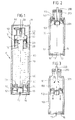
- This particular type of reservoir R in fact consists of a cylindrical tube 10, the bottom 13 of which is open.
- a cover 16 retained by a sleeve 12 adapted to force-engage around the lower periphery 14 of the tube 10 can however protect this open bottom 13 from untimely pressure from the user or, more simply, from dirt .
- Behind this cover 16, which has a vent hole 17 for this, a scraper piston 50 is able to circulate along the tube 10. A double peripheral lip 51 then seals the piston-tube contact.
- a preferred form of the scraper piston 50 is shown in Figures 1 to 3 in the appendix.
- it comprises a crown 52 which projects sufficiently to come into abutment on the cover 16 when the piston 50 is in the low position (associated with the maximum capacity of the tube 10).
- a crown 53 also extends. Its diameter, greater than that of the previous crown 52, is calculated so that a distribution valve V set on the neck 15 of the tube 10 is able to take place at the within the crown 53 when the piston 50 is in the high position (associated with the minimum capacity of the tube 10). The crown 53 is then in abutment against the nozzle of the neck 15.
- the introduction of the product into such a tube 10 can take place in two different ways as soon as the known techniques of filling at atmospheric pressure are implemented.
- the first (not shown) provides that the piston 50 remains in the low position throughout the operation.
- An injector is then lowered through the open neck 15 of the tube 10 to the immediate vicinity of the piston 50. It delivers product and is raised relative to the tube 10 as the quantity of product injected increases. Care is then taken to keep the end of the injector above the surface of the product. This in fact limits the risks of air bubbles remaining trapped in the mass already introduced. In practice, however, the inclusion of small volumes of air remains inevitable. And the presence of the crown 53 promotes this undesired phenomenon in this case.
- the second filling method already disclosed consists in placing the piston 50 in the high position beforehand (cf. fig. 2).
- An injector 200 is introduced through the neck 15 of the tube 10 as in the first method. However, its end 201 is simply disposed within the crown 53 of the piston 50. It is moreover secured by means of a plug 210 sealing the neck 15 and is thus isolated from the outside.
- product 80 is then injected with sufficient pressure to cause the scraper piston 50 to descend as new quantities of product are introduced.
- the present invention aims to provide a method of packaging liquid to pasty products in a vacuum dispenser in which the filling of the reservoirs of the dispensers completely avoids the trapping of air bubbles. It must be particularly effective when the reservoirs are scraper piston tubes like those just described.
- a method for packaging a liquid to pasty product in a vacuum dispenser comprising an operation of filling said tank with said product, characterized in that said filling operation is carried out while said tank is in its configuration of maximum capacity at l inside an airtight enclosure where there is a vacuum.
- said filling means comprise an injector having one end, said injector being secured to said bell so that, when said hermetic enclosure is formed, said end is engaged in said opening of said tank, a valve being moreover adapted to closing said injector outside of said filling operation so that said air vacuum created in said hermetic enclosure does not lead to a suction of said product into said enclosure through said injector.
- an amount of said product equal to said maximum capacity of said tank isolated using a metering cylinder is advantageously pushed back by a piston through said injector, said valve being a suitable hydraulic valve. to deliver passage to said quantity of said product as a function of the force developed by said piston.
- Said metering cylinder is then for example filled with said product prior to said filling operation from a reserve of said product maintained under vacuum, via a valve.
- said hermetic enclosure is brought back to atmospheric pressure, then said cup and said bell are separated from each other so that said filled reservoir is released.
- said dispensing member is placed in said opening, a vacuum fixing operation of said member then intervening to complete said process.
- said means adapted to vary the capacity of said reservoir consist of a scraper piston, and said dispensing member is a precompression metering pump suitable for dispensing creams.
- the present invention also discloses a device for implementing the above method. It consists at least of a cup having an open top to receive said tank so that its opening is present on said top, of a bell adapted to close said so as to constitute said sealed enclosure, filling means being in said bell, means for creating a vacuum in said sealed enclosure.
- the distributors obtained by the present process form part of the invention. They have the particularity that their content consists exclusively of said product, any inclusion of air being notably absent.
- FIGS. 1 to 3 If the scraper piston tube shown in FIGS. 1 to 3 has already been described above in the part of this memo devoted to the prior art, it is here appropriate to add how a dispenser is advantageously presented at the end of present vacuum packaging method using this type of reservoir R.
- the section of Figure 1 illustrates such a dispenser.
- a distribution valve V Partly introduced into the neck 15 of the tube 10 is in fact a distribution valve V.
- a precompression dosing pump adapted to the distribution of creams.
- a valve stem 40 protrudes outside, protruding out of a spinner 30.
- the latter comprises for example an annular wheelbase 32 to rest on the periphery of the neck 15 of the tube 10.
- a seal 23 is however interposed between this periphery and the wheelbase 32. In this way a crimping flange 20 is able to pinch the corresponding stack so as not only to subject valve V to tube 10, but also to make the attachment particularly watertight.
- a guiding ferrule 92 is passed around the neck 15 of the tube 10. It guarantees proper actuation of the valve stem 40 by means of a push button 90.
- the latter in this case determines a lateral distribution of the product which, from the rod 40, is deflected up to the nozzle 91 within a bent channel of the push button 90.
- a cap 11 is finally adapted to fit onto the tube 10 over the dispensing members which have just been quickly reviewed. Recall that they are specified here only as an illustration of a dispenser obtainable by the present vacuum packaging process.
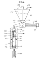
- FIG. 4 A particularly important phase of this process in the context of the present invention is illustrated in the diagram in FIG. 4. It is the operation of filling the reservoir R.
- the latter is then placed in a bucket 110 having for example the shape of a case with a bottom, but without top.
- the housing is cylindrical and its internal diameter is adapted to easy engagement as well as to effective maintenance of the reservoir R.
- the latter is also maintained so as to have its maximum capacity.
- its scraper piston 50 is in the low position.
- the cover 16 and the sleeve 12 are advantageously already assembled to the casing 10. In fact, the filling operation generally takes place at the product manufacturer and the tanks are delivered by another company which takes care to spare this manufacturer any task not related to the actual packaging.
- the neck 15 of the reservoir R is finally presented on the open top of the bucket 110 so that it is accessible.
- a bell 210 is brought into contact with the bucket 110 in order to close it.
- this can be done by means of a cylinder 100 adapted to raise the bucket as soon as it is plumb with the bell 210.
- a cylinder 100 adapted to raise the bucket as soon as it is plumb with the bell 210.
- closing the bucket by the bell is likely to have recourse to means of relative displacement of a greater or lesser complexity, the present presentation sticking rather to an operating principle.
- the bell 210 is for example provided below with a thick seal 211 in order to ensure the tightness of its contact with the bucket 110. Consequently, the reservoir R is found in a hermetic enclosure. However, it communicates through at least one suitable conduit 212 with a vacuum pump system. This is not shown and only an arrow coming from this conduit 212 materializes the evacuation of the air initially contained in the enclosure.
- an injector 200 adapted for the introduction of the product into the reservoir R. It is for example a cannula subject to a support 202 integral with the bell 210. Its height is in this case calculated so that its end 201 automatically takes place within the neck 15 as soon as the bell and cup are in contact. In other words, no relative movement of this end 201 and of the reservoir R is planned thereafter and, in particular, while the filling of the reservoir is taking place.
- the product 80 which is then introduced by the injector 200 is for example taken from a hopper 250. In this case, it is rather maintained under vacuum. This is shown diagrammatically in FIG. 4 by the arrow leaving the duct 252.
- an agitator 261 driven by a motor 260 can advantageously prevent the more or less compact product from preventing the evacuation of the content of the hopper 250 through its lower orifice 251.
- FIG. 4 schematically shows a three-way valve. It is for example a ball valve, its male part comprising three holes. In this way, either the hopper 250 and a metering cylinder 240 shown diagrammatically in FIG. 4 to the right of the valve 230 can be placed in communication, or this metering cylinder 240 and the bell 210.
- a hydraulic valve 220 In the latter case, however, the communication is further regulated by a hydraulic valve 220.
- the diagram in FIG. 4 is limited to recalling that such a valve comprises a needle 221 adapted to collaborate with a valve seat.
- this seat is advantageously provided by the end 201 of the injector 200, the latter being for this purpose narrowed relative to the internal channel of the injector 200 in which the needle 221 takes place.
- the hydraulic valve 220 also includes a piston head retained protected from the product on the side opposite the needle 221 by a spring (not shown) while the product under pressure can infiltrate under the head on the side where the needle 221 takes root.
- the filling operation ensures that at no time during its transfer, the dose of product to be introduced into the reservoir R is not in contact with the air. It cannot therefore contain the slightest bubble.
- the packaging process can then be completed by a vacuum sealing operation of the tank R according to a known embodiment.
- the pig piston tube which is more particularly concerned here, its valve V is advantageously crimped under vacuum according to the teaching of the application FR 89-14260 cited above. Note that it is then more practical to restore the atmospheric pressure in the enclosure of FIG. 4 in order to separate the cup 110 from the bell 210 and to be able to arrange the valve V in the neck 15 of the tank. Contact of the free surface of the product with the ambient air thus called into question, does not however risk losing the benefit of the filling operation as described above. Also the vacuum dispensers containing such doses devoid of totally air are also part of the present invention.
Landscapes
- Chemical & Material Sciences (AREA)
- Dispersion Chemistry (AREA)
- Engineering & Computer Science (AREA)
- Mechanical Engineering (AREA)
- Basic Packing Technique (AREA)
- Vacuum Packaging (AREA)
- Closures For Containers (AREA)
Applications Claiming Priority (2)
| Application Number | Priority Date | Filing Date | Title |
|---|---|---|---|
| FR9012806A FR2668118B1 (fr) | 1990-10-17 | 1990-10-17 | Procede de conditionnement de produits liquides a pateux en distributeur sous vide, dispositif pour le mettre en óoeuvre et distributeurs ainsi obtenus. |
| FR9012806 | 1990-10-17 |
Publications (2)
| Publication Number | Publication Date |
|---|---|
| EP0481854A1 true EP0481854A1 (de) | 1992-04-22 |
| EP0481854B1 EP0481854B1 (de) | 1994-08-24 |
Family
ID=9401302
Family Applications (1)
| Application Number | Title | Priority Date | Filing Date |
|---|---|---|---|
| EP91402717A Expired - Lifetime EP0481854B1 (de) | 1990-10-17 | 1991-10-11 | Verfahren zum Vakuumverpacken von flüssigen oder pastösen Produkten in Spender, Vorrichtung dafür und so erhaltene Spender |
Country Status (5)
| Country | Link |
|---|---|
| US (1) | US5217050A (de) |
| EP (1) | EP0481854B1 (de) |
| JP (1) | JP3208548B2 (de) |
| DE (1) | DE69103609T2 (de) |
| FR (1) | FR2668118B1 (de) |
Cited By (3)
| Publication number | Priority date | Publication date | Assignee | Title |
|---|---|---|---|---|
| FR2706415A1 (fr) * | 1993-06-15 | 1994-12-23 | Kalix Dupuy | Dispositif et procédé de remplissage sous vide. |
| FR2957839A1 (fr) * | 2010-03-25 | 2011-09-30 | Valois Sas | Procede de moulage par injection d'une piece creuse en matiere plastique. |
| US8726615B2 (en) | 2008-07-01 | 2014-05-20 | Aptar France Sas | Method for conditioning a fluid product in a dispenser |
Families Citing this family (20)
| Publication number | Priority date | Publication date | Assignee | Title |
|---|---|---|---|---|
| GB9122909D0 (en) * | 1991-10-29 | 1991-12-11 | Unilever Plc | Toothpaste composition |
| US5262151A (en) * | 1991-11-25 | 1993-11-16 | Montgomery Robert E | Stabilized enzymatic antimicrobial compositions |
| US5277340A (en) * | 1992-11-05 | 1994-01-11 | Risdon Corporation | Dispensing container |
| US5479967A (en) * | 1994-01-24 | 1996-01-02 | B. Braun Medical, Inc. | Method of filling a bourdon tube with a gel substance |
| JP2882756B2 (ja) | 1994-10-12 | 1999-04-12 | 昭和高分子株式会社 | 脂肪族ポリエステル組成物からなる延伸中空成形体 |
| EP1013566B1 (de) * | 1995-03-09 | 2009-01-21 | Osaka Shipbuilding Co., Ltd. | Verfahren zum herstellen eines doppel-aerosolbehälters, sowie dieser behälter |
| DE19741957A1 (de) * | 1997-09-23 | 1999-03-25 | Wischerath Josef Gmbh Co Kg | Verfahren zum Befüllen eines Spenders und Spender |
| DE19918721A1 (de) * | 1999-04-24 | 2000-11-02 | Inova Pac Systeme Gmbh | Verfahren und Vorrichtung zum Befüllen von nadelfreien Injektoren |
| KR100582672B1 (ko) | 2005-12-29 | 2006-05-23 | 주식회사 첨단자동기 | 액체 충전장치 |
| CH698602B1 (de) * | 2006-08-09 | 2009-09-15 | Dopag Dosiertechnik Und Pneuma | Vorrichtung und Verfahren zum Befüllen von Spritzenzylindern. |
| CN101652640B (zh) * | 2007-04-10 | 2011-08-31 | 梅特勒-托利多公开股份有限公司 | 用于实验室物质的储存和保护的容器单元 |
| FR2949438B1 (fr) * | 2009-08-25 | 2011-10-28 | Valois Sas | Ensemble et procede de conditionnement sous vide. |
| CN101774521A (zh) * | 2010-01-15 | 2010-07-14 | 周数理 | 伺服电机驱动的螺杆泵灌装装置 |
| CN103145078B (zh) * | 2013-03-30 | 2014-12-10 | 山东默锐科技有限公司 | 一种熔融金属钠灌装设备 |
| FR3046944B1 (fr) * | 2016-01-22 | 2022-04-01 | Capsum | Dispositif de conditionnement et de distribution sans reprise d'air d'un produit, notamment a plusieurs phases, bague de purge et procede associes |
| DE102018100353B4 (de) * | 2018-01-09 | 2020-08-06 | Khs Gmbh | Füllvorrichtung |
| DE102018200291A1 (de) * | 2018-01-10 | 2019-07-11 | Optima consumer GmbH | Vorrichtung und Verfahren zum Entgasen und Begasen von Behältern |
| WO2022271186A1 (en) * | 2021-06-25 | 2022-12-29 | Thrivo Technologies Inc. | Systems and Methods of Preserving Customized Cosmetic Products |
| CN117651681A (zh) * | 2021-07-08 | 2024-03-05 | 株式会社松风 | 牙科用糊剂填充装置以及方法 |
| US20250263283A1 (en) * | 2024-02-21 | 2025-08-21 | Clear IP Corporation | Injection system |
Citations (3)
| Publication number | Priority date | Publication date | Assignee | Title |
|---|---|---|---|---|
| FR1291224A (fr) * | 1961-05-29 | 1962-04-20 | Agfa Ag | Dispositif de remplissage pour bouteilles de matière synthétique |
| US3996725A (en) * | 1973-05-21 | 1976-12-14 | The Dow Chemical Company | Apparatus for filling and hermetically sealing thermoplastic containers under vacuum |
| EP0276983A2 (de) * | 1987-01-28 | 1988-08-03 | Unilever Plc | Dosierspender für viskose Flüssigkeiten |
Family Cites Families (3)
| Publication number | Priority date | Publication date | Assignee | Title |
|---|---|---|---|---|
| US1893716A (en) * | 1930-01-13 | 1933-01-10 | Vacuum Packing Corp | Filling, vacuumizing, sterilizing, and sealing machine |
| US3911972A (en) * | 1971-05-27 | 1975-10-14 | Ernst Hubers | Method of filling containers enclosing solid matter with an accurate amount of liquid |
| US4254806A (en) * | 1979-04-25 | 1981-03-10 | Robert M. Elsworth | Apparatus for filling caulking tubes in a clean manner |
-
1990
- 1990-10-17 FR FR9012806A patent/FR2668118B1/fr not_active Expired - Fee Related
-
1991
- 1991-10-11 EP EP91402717A patent/EP0481854B1/de not_active Expired - Lifetime
- 1991-10-11 DE DE69103609T patent/DE69103609T2/de not_active Expired - Lifetime
- 1991-10-17 US US07/777,925 patent/US5217050A/en not_active Expired - Lifetime
- 1991-10-17 JP JP29844991A patent/JP3208548B2/ja not_active Expired - Fee Related
Patent Citations (3)
| Publication number | Priority date | Publication date | Assignee | Title |
|---|---|---|---|---|
| FR1291224A (fr) * | 1961-05-29 | 1962-04-20 | Agfa Ag | Dispositif de remplissage pour bouteilles de matière synthétique |
| US3996725A (en) * | 1973-05-21 | 1976-12-14 | The Dow Chemical Company | Apparatus for filling and hermetically sealing thermoplastic containers under vacuum |
| EP0276983A2 (de) * | 1987-01-28 | 1988-08-03 | Unilever Plc | Dosierspender für viskose Flüssigkeiten |
Cited By (3)
| Publication number | Priority date | Publication date | Assignee | Title |
|---|---|---|---|---|
| FR2706415A1 (fr) * | 1993-06-15 | 1994-12-23 | Kalix Dupuy | Dispositif et procédé de remplissage sous vide. |
| US8726615B2 (en) | 2008-07-01 | 2014-05-20 | Aptar France Sas | Method for conditioning a fluid product in a dispenser |
| FR2957839A1 (fr) * | 2010-03-25 | 2011-09-30 | Valois Sas | Procede de moulage par injection d'une piece creuse en matiere plastique. |
Also Published As
| Publication number | Publication date |
|---|---|
| DE69103609T2 (de) | 1995-04-20 |
| JPH0516913A (ja) | 1993-01-26 |
| FR2668118A1 (fr) | 1992-04-24 |
| US5217050A (en) | 1993-06-08 |
| FR2668118B1 (fr) | 1993-12-24 |
| DE69103609D1 (de) | 1994-09-29 |
| EP0481854B1 (de) | 1994-08-24 |
| JP3208548B2 (ja) | 2001-09-17 |
Similar Documents
| Publication | Publication Date | Title |
|---|---|---|
| EP0481854B1 (de) | Verfahren zum Vakuumverpacken von flüssigen oder pastösen Produkten in Spender, Vorrichtung dafür und so erhaltene Spender | |
| EP0509179B1 (de) | Verfahren zum Vakuumverpacken von Produkten, insbesondere kosmetische oder pharmazeutische Produkte, in Behältern mit veränderbaren Grössen, verschlossen durch ein Verteilungsorgan ohne Abluft | |
| EP1064102B1 (de) | Behälter, verfahren zur befüllung dieses behälter und abgabevorrichtung für das im behälter enthaltene pulver | |
| EP0378935B1 (de) | Vorrichtung zum Spenden einer Flüssigkeit oder einer Creme in Tropfen kleinen Volumens | |
| EP2313319B1 (de) | Verfahren zum verpacken eines fluidprodukts in einem spender | |
| EP1877314B1 (de) | Verfahren und vorrichtung zum füllen eines behältnisses mit variablem nutzvolumen | |
| EP1572375B1 (de) | Manuell betätigte dosierpumpe | |
| FR2815328A1 (fr) | Dispositif de connexion entre un recipient et un contenant et ensemble pret a l'emploi comprenant un tel dispositif | |
| WO1999034853A1 (fr) | Dispositif de pulverisation de produit fluide | |
| FR2773355A1 (fr) | Dispositif de conditionnement et de distribution comportant un reservoir rempli sous vide et procede de fabrication | |
| EP0499538B1 (de) | Verpackung für pastöse Medien | |
| EP2092985B1 (de) | Behälter mit Steigrohr | |
| EP3969084A1 (de) | Vorrichtung zur ausgabe eines fluidprodukts | |
| FR2784969A1 (fr) | Reservoir pourvu d'un dispositif de fermeture et de remplissage et dispositif de distribution de produit fluide comportant un tel reservoir | |
| FR3041219A1 (de) | ||
| FR2685285A1 (fr) | Procede de conditionnement d'un produit liquide quelconque et flacon obtenu par ce procede. | |
| FR2668119A2 (fr) | Procede de conditionnement sous vide en distributeurs a enveloppe rigide et distributeurs correspondants. | |
| EP3634883B1 (de) | Dosierventil und fluidproduktabgabevorrichtung mit solch einem ventil | |
| FR2898114A1 (fr) | Procede et dispositif de conservation et de distribution d'un produit dans un recipient muni d'une poche et recipient rechargeable. | |
| FR2649616A1 (fr) | Seringue et aiguille d'injection a usage unique | |
| EP1103490B1 (de) | Zerstäuber mit Treibgas | |
| FR2847887A1 (fr) | Reservoir de produits fluides | |
| EP2703090B1 (de) | Sprühfläschchen für Flüssigprodukt | |
| EP4255825A1 (de) | Vorrichtung zur abgabe eines flüssigprodukts mit dosisanzeige |
Legal Events
| Date | Code | Title | Description |
|---|---|---|---|
| PUAI | Public reference made under article 153(3) epc to a published international application that has entered the european phase |
Free format text: ORIGINAL CODE: 0009012 |
|
| AK | Designated contracting states |
Kind code of ref document: A1 Designated state(s): DE FR GB IT |
|
| 17P | Request for examination filed |
Effective date: 19920721 |
|
| RAP1 | Party data changed (applicant data changed or rights of an application transferred) |
Owner name: SOCIETE ANONYME DITE:ETABLISSEMENTS VALOIS |
|
| 17Q | First examination report despatched |
Effective date: 19931029 |
|
| GRAA | (expected) grant |
Free format text: ORIGINAL CODE: 0009210 |
|
| AK | Designated contracting states |
Kind code of ref document: B1 Designated state(s): DE FR GB IT |
|
| REF | Corresponds to: |
Ref document number: 69103609 Country of ref document: DE Date of ref document: 19940929 |
|
| ITF | It: translation for a ep patent filed | ||
| GBT | Gb: translation of ep patent filed (gb section 77(6)(a)/1977) |
Effective date: 19941129 |
|
| PLBE | No opposition filed within time limit |
Free format text: ORIGINAL CODE: 0009261 |
|
| STAA | Information on the status of an ep patent application or granted ep patent |
Free format text: STATUS: NO OPPOSITION FILED WITHIN TIME LIMIT |
|
| 26N | No opposition filed | ||
| REG | Reference to a national code |
Ref country code: FR Ref legal event code: CD Ref country code: FR Ref legal event code: CA Ref country code: FR Ref legal event code: TP |
|
| REG | Reference to a national code |
Ref country code: GB Ref legal event code: IF02 |
|
| PGFP | Annual fee paid to national office [announced via postgrant information from national office to epo] |
Ref country code: GB Payment date: 20100923 Year of fee payment: 20 |
|
| PGFP | Annual fee paid to national office [announced via postgrant information from national office to epo] |
Ref country code: FR Payment date: 20101116 Year of fee payment: 20 |
|
| PGFP | Annual fee paid to national office [announced via postgrant information from national office to epo] |
Ref country code: DE Payment date: 20101012 Year of fee payment: 20 |
|
| PGFP | Annual fee paid to national office [announced via postgrant information from national office to epo] |
Ref country code: IT Payment date: 20101027 Year of fee payment: 20 |
|
| REG | Reference to a national code |
Ref country code: DE Ref legal event code: R071 Ref document number: 69103609 Country of ref document: DE |
|
| REG | Reference to a national code |
Ref country code: DE Ref legal event code: R071 Ref document number: 69103609 Country of ref document: DE |
|
| REG | Reference to a national code |
Ref country code: GB Ref legal event code: PE20 Expiry date: 20111010 |
|
| PG25 | Lapsed in a contracting state [announced via postgrant information from national office to epo] |
Ref country code: GB Free format text: LAPSE BECAUSE OF EXPIRATION OF PROTECTION Effective date: 20111010 |
|
| PG25 | Lapsed in a contracting state [announced via postgrant information from national office to epo] |
Ref country code: DE Free format text: LAPSE BECAUSE OF EXPIRATION OF PROTECTION Effective date: 20111012 |