EP0481855A1 - Prothèse d'articulation sphérique - Google Patents
Prothèse d'articulation sphérique Download PDFInfo
- Publication number
- EP0481855A1 EP0481855A1 EP91402719A EP91402719A EP0481855A1 EP 0481855 A1 EP0481855 A1 EP 0481855A1 EP 91402719 A EP91402719 A EP 91402719A EP 91402719 A EP91402719 A EP 91402719A EP 0481855 A1 EP0481855 A1 EP 0481855A1
- Authority
- EP
- European Patent Office
- Prior art keywords
- balls
- value
- housing
- cup
- prosthesis according
- Prior art date
- Legal status (The legal status is an assumption and is not a legal conclusion. Google has not performed a legal analysis and makes no representation as to the accuracy of the status listed.)
- Granted
Links
- 239000000463 material Substances 0.000 claims description 11
- 125000006850 spacer group Chemical group 0.000 claims description 5
- 244000144619 Abrus precatorius Species 0.000 claims description 4
- 101150038956 cup-4 gene Proteins 0.000 abstract description 10
- 210000003127 knee Anatomy 0.000 abstract description 3
- 238000004519 manufacturing process Methods 0.000 abstract description 2
- 239000002245 particle Substances 0.000 description 6
- 210000002540 macrophage Anatomy 0.000 description 5
- 210000000988 bone and bone Anatomy 0.000 description 3
- RTAQQCXQSZGOHL-UHFFFAOYSA-N Titanium Chemical compound [Ti] RTAQQCXQSZGOHL-UHFFFAOYSA-N 0.000 description 2
- 210000003414 extremity Anatomy 0.000 description 2
- 210000002414 leg Anatomy 0.000 description 2
- 229910052719 titanium Inorganic materials 0.000 description 2
- 239000010936 titanium Substances 0.000 description 2
- 210000000617 arm Anatomy 0.000 description 1
- 230000000295 complement effect Effects 0.000 description 1
- 239000012141 concentrate Substances 0.000 description 1
- 229920001971 elastomer Polymers 0.000 description 1
- 239000000806 elastomer Substances 0.000 description 1
- 239000006260 foam Substances 0.000 description 1
- 210000001624 hip Anatomy 0.000 description 1
- 210000004394 hip joint Anatomy 0.000 description 1
- 210000001503 joint Anatomy 0.000 description 1
- 230000037231 joint health Effects 0.000 description 1
- 210000000265 leukocyte Anatomy 0.000 description 1
- 230000014759 maintenance of location Effects 0.000 description 1
- 210000003049 pelvic bone Anatomy 0.000 description 1
- 210000004197 pelvis Anatomy 0.000 description 1
- 238000005096 rolling process Methods 0.000 description 1
- 210000000689 upper leg Anatomy 0.000 description 1
Images


Classifications
-
- A—HUMAN NECESSITIES
- A61—MEDICAL OR VETERINARY SCIENCE; HYGIENE
- A61F—FILTERS IMPLANTABLE INTO BLOOD VESSELS; PROSTHESES; DEVICES PROVIDING PATENCY TO, OR PREVENTING COLLAPSING OF, TUBULAR STRUCTURES OF THE BODY, e.g. STENTS; ORTHOPAEDIC, NURSING OR CONTRACEPTIVE DEVICES; FOMENTATION; TREATMENT OR PROTECTION OF EYES OR EARS; BANDAGES, DRESSINGS OR ABSORBENT PADS; FIRST-AID KITS
- A61F2/00—Filters implantable into blood vessels; Prostheses, i.e. artificial substitutes or replacements for parts of the body; Appliances for connecting them with the body; Devices providing patency to, or preventing collapsing of, tubular structures of the body, e.g. stents
- A61F2/02—Prostheses implantable into the body
- A61F2/30—Joints
- A61F2/32—Joints for the hip
-
- A—HUMAN NECESSITIES
- A61—MEDICAL OR VETERINARY SCIENCE; HYGIENE
- A61F—FILTERS IMPLANTABLE INTO BLOOD VESSELS; PROSTHESES; DEVICES PROVIDING PATENCY TO, OR PREVENTING COLLAPSING OF, TUBULAR STRUCTURES OF THE BODY, e.g. STENTS; ORTHOPAEDIC, NURSING OR CONTRACEPTIVE DEVICES; FOMENTATION; TREATMENT OR PROTECTION OF EYES OR EARS; BANDAGES, DRESSINGS OR ABSORBENT PADS; FIRST-AID KITS
- A61F2/00—Filters implantable into blood vessels; Prostheses, i.e. artificial substitutes or replacements for parts of the body; Appliances for connecting them with the body; Devices providing patency to, or preventing collapsing of, tubular structures of the body, e.g. stents
- A61F2/02—Prostheses implantable into the body
- A61F2/30—Joints
- A61F2/32—Joints for the hip
- A61F2/36—Femoral heads ; Femoral endoprostheses
-
- A—HUMAN NECESSITIES
- A61—MEDICAL OR VETERINARY SCIENCE; HYGIENE
- A61F—FILTERS IMPLANTABLE INTO BLOOD VESSELS; PROSTHESES; DEVICES PROVIDING PATENCY TO, OR PREVENTING COLLAPSING OF, TUBULAR STRUCTURES OF THE BODY, e.g. STENTS; ORTHOPAEDIC, NURSING OR CONTRACEPTIVE DEVICES; FOMENTATION; TREATMENT OR PROTECTION OF EYES OR EARS; BANDAGES, DRESSINGS OR ABSORBENT PADS; FIRST-AID KITS
- A61F2/00—Filters implantable into blood vessels; Prostheses, i.e. artificial substitutes or replacements for parts of the body; Appliances for connecting them with the body; Devices providing patency to, or preventing collapsing of, tubular structures of the body, e.g. stents
- A61F2/02—Prostheses implantable into the body
- A61F2/30—Joints
- A61F2/38—Joints for elbows or knees
-
- A—HUMAN NECESSITIES
- A61—MEDICAL OR VETERINARY SCIENCE; HYGIENE
- A61F—FILTERS IMPLANTABLE INTO BLOOD VESSELS; PROSTHESES; DEVICES PROVIDING PATENCY TO, OR PREVENTING COLLAPSING OF, TUBULAR STRUCTURES OF THE BODY, e.g. STENTS; ORTHOPAEDIC, NURSING OR CONTRACEPTIVE DEVICES; FOMENTATION; TREATMENT OR PROTECTION OF EYES OR EARS; BANDAGES, DRESSINGS OR ABSORBENT PADS; FIRST-AID KITS
- A61F2/00—Filters implantable into blood vessels; Prostheses, i.e. artificial substitutes or replacements for parts of the body; Appliances for connecting them with the body; Devices providing patency to, or preventing collapsing of, tubular structures of the body, e.g. stents
- A61F2/02—Prostheses implantable into the body
- A61F2/30—Joints
- A61F2002/30001—Additional features of subject-matter classified in A61F2/28, A61F2/30 and subgroups thereof
- A61F2002/30316—The prosthesis having different structural features at different locations within the same prosthesis; Connections between prosthetic parts; Special structural features of bone or joint prostheses not otherwise provided for
- A61F2002/30535—Special structural features of bone or joint prostheses not otherwise provided for
- A61F2002/30563—Special structural features of bone or joint prostheses not otherwise provided for having elastic means or damping means, different from springs, e.g. including an elastomeric core or shock absorbers
-
- A—HUMAN NECESSITIES
- A61—MEDICAL OR VETERINARY SCIENCE; HYGIENE
- A61F—FILTERS IMPLANTABLE INTO BLOOD VESSELS; PROSTHESES; DEVICES PROVIDING PATENCY TO, OR PREVENTING COLLAPSING OF, TUBULAR STRUCTURES OF THE BODY, e.g. STENTS; ORTHOPAEDIC, NURSING OR CONTRACEPTIVE DEVICES; FOMENTATION; TREATMENT OR PROTECTION OF EYES OR EARS; BANDAGES, DRESSINGS OR ABSORBENT PADS; FIRST-AID KITS
- A61F2/00—Filters implantable into blood vessels; Prostheses, i.e. artificial substitutes or replacements for parts of the body; Appliances for connecting them with the body; Devices providing patency to, or preventing collapsing of, tubular structures of the body, e.g. stents
- A61F2/02—Prostheses implantable into the body
- A61F2/30—Joints
- A61F2002/30001—Additional features of subject-matter classified in A61F2/28, A61F2/30 and subgroups thereof
- A61F2002/30621—Features concerning the anatomical functioning or articulation of the prosthetic joint
- A61F2002/30639—Features concerning the anatomical functioning or articulation of the prosthetic joint having rolling elements between both articulating surfaces
-
- A—HUMAN NECESSITIES
- A61—MEDICAL OR VETERINARY SCIENCE; HYGIENE
- A61F—FILTERS IMPLANTABLE INTO BLOOD VESSELS; PROSTHESES; DEVICES PROVIDING PATENCY TO, OR PREVENTING COLLAPSING OF, TUBULAR STRUCTURES OF THE BODY, e.g. STENTS; ORTHOPAEDIC, NURSING OR CONTRACEPTIVE DEVICES; FOMENTATION; TREATMENT OR PROTECTION OF EYES OR EARS; BANDAGES, DRESSINGS OR ABSORBENT PADS; FIRST-AID KITS
- A61F2/00—Filters implantable into blood vessels; Prostheses, i.e. artificial substitutes or replacements for parts of the body; Appliances for connecting them with the body; Devices providing patency to, or preventing collapsing of, tubular structures of the body, e.g. stents
- A61F2/02—Prostheses implantable into the body
- A61F2/30—Joints
- A61F2/32—Joints for the hip
- A61F2002/3233—Joints for the hip having anti-luxation means for preventing complete dislocation of the femoral head from the acetabular cup
-
- A—HUMAN NECESSITIES
- A61—MEDICAL OR VETERINARY SCIENCE; HYGIENE
- A61F—FILTERS IMPLANTABLE INTO BLOOD VESSELS; PROSTHESES; DEVICES PROVIDING PATENCY TO, OR PREVENTING COLLAPSING OF, TUBULAR STRUCTURES OF THE BODY, e.g. STENTS; ORTHOPAEDIC, NURSING OR CONTRACEPTIVE DEVICES; FOMENTATION; TREATMENT OR PROTECTION OF EYES OR EARS; BANDAGES, DRESSINGS OR ABSORBENT PADS; FIRST-AID KITS
- A61F2/00—Filters implantable into blood vessels; Prostheses, i.e. artificial substitutes or replacements for parts of the body; Appliances for connecting them with the body; Devices providing patency to, or preventing collapsing of, tubular structures of the body, e.g. stents
- A61F2/02—Prostheses implantable into the body
- A61F2/30—Joints
- A61F2/32—Joints for the hip
- A61F2/34—Acetabular cups
- A61F2002/3445—Acetabular cups having a number of shells different from two
- A61F2002/3448—Multiple cups made of three or more concentric shells fitted or nested into one another
-
- A—HUMAN NECESSITIES
- A61—MEDICAL OR VETERINARY SCIENCE; HYGIENE
- A61F—FILTERS IMPLANTABLE INTO BLOOD VESSELS; PROSTHESES; DEVICES PROVIDING PATENCY TO, OR PREVENTING COLLAPSING OF, TUBULAR STRUCTURES OF THE BODY, e.g. STENTS; ORTHOPAEDIC, NURSING OR CONTRACEPTIVE DEVICES; FOMENTATION; TREATMENT OR PROTECTION OF EYES OR EARS; BANDAGES, DRESSINGS OR ABSORBENT PADS; FIRST-AID KITS
- A61F2/00—Filters implantable into blood vessels; Prostheses, i.e. artificial substitutes or replacements for parts of the body; Appliances for connecting them with the body; Devices providing patency to, or preventing collapsing of, tubular structures of the body, e.g. stents
- A61F2/02—Prostheses implantable into the body
- A61F2/30—Joints
- A61F2/32—Joints for the hip
- A61F2/34—Acetabular cups
- A61F2002/348—Additional features
- A61F2002/3493—Spherical shell significantly greater than a hemisphere, e.g. extending over more than 200 degrees
-
- A—HUMAN NECESSITIES
- A61—MEDICAL OR VETERINARY SCIENCE; HYGIENE
- A61F—FILTERS IMPLANTABLE INTO BLOOD VESSELS; PROSTHESES; DEVICES PROVIDING PATENCY TO, OR PREVENTING COLLAPSING OF, TUBULAR STRUCTURES OF THE BODY, e.g. STENTS; ORTHOPAEDIC, NURSING OR CONTRACEPTIVE DEVICES; FOMENTATION; TREATMENT OR PROTECTION OF EYES OR EARS; BANDAGES, DRESSINGS OR ABSORBENT PADS; FIRST-AID KITS
- A61F2/00—Filters implantable into blood vessels; Prostheses, i.e. artificial substitutes or replacements for parts of the body; Appliances for connecting them with the body; Devices providing patency to, or preventing collapsing of, tubular structures of the body, e.g. stents
- A61F2/02—Prostheses implantable into the body
- A61F2/30—Joints
- A61F2/32—Joints for the hip
- A61F2/36—Femoral heads ; Femoral endoprostheses
- A61F2/3609—Femoral heads or necks; Connections of endoprosthetic heads or necks to endoprosthetic femoral shafts
- A61F2002/3611—Heads or epiphyseal parts of femur
Definitions
- the present invention relates to patellar prostheses such as those which are implanted in the human body to restore damaged joints, for example during an illness or an accident, in particular those connecting the bones of the limbs, arms and legs, to the trunk. , but also those connecting the bones of the different parts of these limbs, for example the hip joint, that of the knee, etc.
- Any ball joint essentially comprises a male part generally constituted by a portion of sphere and a female part in the shape of a cup complementary to the portion of sphere and of the same radius.
- the sphere portion is mounted by any means on a fixing lug intended to be implanted in the femur, and the cup is able to be implanted in the pelvic bone, the sphere portion being held in the cup by all means of retention and being able to move therein in rotation so as to allow the same movements of the leg relative to the pelvis as those which are normally possible with a healthy joint.
- the cup in which is housed in rotation the male spherical head of the ball joint is generally made of a less hard material than that in which this spherical head is made. It follows that the friction of the two materials against each other during the rotation of the spherical head in the cup produces wear particles of the most tender material.
- a patellar prosthesis which comprises a cup defining a hemispherical hollow housing with a first value of radius of curvature, a portion of sphere having a second value of radius of curvature, this second value being less than the first value, a plurality of spherical balls, the spherical balls having a diameter of a third value equal to the difference between the prayer and second values of radius of curvature, the portion of sphere being located in the housing of the cup so that its center and that of the housing are combined to define, between it and the housing, a hemispherical space, the balls being arranged in the hemispherical space between the wall of the housing and the wall of the sphere portion, and at their contact, and means for retaining the balls in the hemispherical space.
- patellar prosthesis structure described above gives good results.
- the object of the present invention is to produce a patellar prosthesis which makes it possible to further reduce the quantity produced of wear particles and to favor the rotation of the balls between themselves and with respect to the surfaces which surround them.
- the present invention relates to a patellar prosthesis comprising: at least one cup defining a hollow hemispherical recess of a prayer value of radius of curvature, at least a portion of a sphere having a second value of radius of curvature, said second value being less than said prayer value, a plurality of spherical balls having a diameter of a third value equal to the difference between said prayer and second values of radius of curvature, said portion of sphere being located in said housing of the cup so that its center and that of the housing are combined to define, between it and said housing, a hemispherical space, said balls being arranged in said hemispherical space between the wall of said housing and the wall of said portion of sphere, and means for retaining said balls in said hemispherical space, characterized in that it further comprises a cavity produced in said cup, said cavity comprising a circular opening defined substantially in the wall of said hemispherical housing and substantially centered on the axis of
- the patellar prosthesis comprises at least one cup 4 defining a substantially hemispherical recess 5 of a radius of curvature "R” having a prayer value, and at least a portion of sphere 6 having a second value of radius of curvature "r", the second value "r" being less at prayer value "R".
- the portion of sphere 6 is located in the housing 5 of the cup 4 so that its center “c" coincides with that "C” of the housing, to define between it and this housing a hemispherical space 12, balls 7 being arranged in this hemispherical space between the wall 9 of the housing 5 and the wall 10 of the sphere portion 6.
- the balls 7 have a diameter of a third value equal to the difference between said first and second values of radius of curvature so that they are in contact with the wall 9 of the housing and the wall 10 of the portion of sphere.
- the prosthesis also comprises a cavity 40 produced in the cup 4.
- This cavity 40 has a circular opening 41 connecting it to the hemispherical space 12 defined substantially in the wall 9 of the housing 5, advantageously at its bottom, and substantially centered on the axis of revolution 43 of this housing.
- the hemispherical space 12 and the cavity 40 are filled with balls 7 so that the latter are distributed there on a single ply and that they are in contact with each other at at least one common point 44.
- the width of the circular opening 41 is substantially equal to the diameter of the balls 7 in contact with the wall of the housing and the portion of the sphere.
- the thickness of the cavity 40 is equal to the diameter of the balls 7.
- this thickness can advantageously be very slightly greater than their diameter, as shown in the figures.
- a prosthesis comprises means 11 for retaining the balls in the hemispherical space 12 and, according to one characteristic of the improvement, the means 11 consist of a ring 45 secured to the cup 4.
- the ring 45 has a configuration which allows the opening 41 to be bordered, at the same time as its surface 46 facing the hemispherical space 12 forms a continuity with the concave surface 47, the most distant with respect to the housing 5, from the cavity 40.
- the cavity 40 is delimited by two parts 51, 52 in the form of a cup placed one inside the other and forming, with the means described below allowing their association, the cup 4.
- the internal section 52 is delimited by two prayer 53 and second 54 respectively concave and convex surfaces, both essentially hemispherical and concentric, the prayer concave surface 53 forming a part of the wall 9 of the hollow housing 5.
- the other section 51 defines a third concave hemispherical surface 55 having a radius of curvature at least equal, if not very slightly greater, to the sum of the radius of curvature of the second convex surface 54 of the inner section 52 and the diameter of the balls 7 in contact with the walls of the housing and of the sphere portion.
- the cup 4 includes means 56 for associating the two cups 51, 52 so that the three prayers 53, second 54 and third 55 surfaces are concentric and the edge 57 of the third surface, at the level of the circular opening 41 of the cavity 40, surrounds the wall portion 58 connecting the two prayer 53 and second 54 surfaces while remaining distant from this wall portion by a distance at least equal to the diameter of the balls 7.
- the means 56 for associate the two sections 51, 52 are advantageously constituted by at least one spacer integral with the second and third surfaces. This spacer, preferably devoid of sharp contour portions, is for example of cylindrical shape of revolution.
- the portion of sphere 6 undergoes a senestrorsum rotation 60.
- it drives the balls 7 located in the housing 5, like the balls 7-1, 7- 2, ..., in dextrorsum rotations, by which they slide on the surface 53 while tending to push the balls 7-3, 7-4, ... which are in the cavity 40, or at its entry, to replenish the hemispherical space 12 by the opening part 41 opposite to that by which the balls 7 were sent into the cavity 40.
- the latter has a thickness very slightly greater than the diameter of the balls, as shown in the figures in which this difference has been exaggerated on purpose.
- FIG. 4 represents an improvement to the embodiment illustrated in FIGS. 1 to 3.
- the balls filling the housing 5 and the cavity 40 are constituted by a plurality of first spherical balls 7 which have a diameter "D "of a value equal to the difference between the first" R “and second" r “values of radius of curvature and by another plurality of second balls 37, these second balls 37 having a fourth value of diameter" d “less than the value "D" of the diameter of the first balls 7.
- the number of second balls 37 is less to that of the prayer prayers 7, so that the spherical part 6 of the prosthesis is well supported by the prayer prayers 7 of diameter "D", while, by being distributed and inserted between the balls 7, the second balls 37 of diameter "d” make it possible to improve the rotation of these prayer beads.
- these second balls 37 somehow play the role of spacers between the balls 7, but with the advantage that these spacers can pivot on themselves.
- the Applicant has produced prototypes of patellar prosthesis according to the invention which have given satisfaction, in which the percentage of second balls 37 relative to the number of prayer prayers 7 was of the order of sixty to seventy percent.
- the housing 5 and the cavity 40 were completely filled with balls 7 and 37 and the balls 37 of smaller diameter therefore occupied substantially thirty-five percent of the volume.
- the cup 4 is constituted by a stack of at least three caps 31, 32 and 33 inside each other, the two inner caps 31 and outer 33 being made of a rigid material, the intermediate cap 32 being made of a material having a certain elasticity of deformation, such as a elastomer or the like.
- the sphere portion 6, the balls 7, 37 and the cup part 4 in contact with the balls are made of the same material such as, for example, a material based on titanium or titanium foam.
- This stack of three caps 31-33 is associated with means 34 for holding the three caps integral with one another and preventing, for example, that they pivot in one another or that they disunite.
- These means 34 are very schematically represented, in FIG. 5, by lugs 35 or the like.
- the value of the angle at the center 14 of the housing 5, as illustrated in FIG. 5, is also advantageous for the value of the angle at the center 14 of the housing 5, as illustrated in FIG. 5, to be greater than 180 degrees, for example so that the portion 8 going beyond the flat angle, from this angle at the center 14, contains at least one ball 7 of diameter "D".
- the value of the angle at the center 15 of the portion of sphere 6 is greater than the value of the angle at the center 14 of the recessed housing so that, as in all patellar prostheses and in particular coxo- femoral, the rotational movement of the male part in the female part can have the amplitude necessary for the restitution of the movements of the joint thus restored.
Landscapes
- Health & Medical Sciences (AREA)
- Orthopedic Medicine & Surgery (AREA)
- Cardiology (AREA)
- Oral & Maxillofacial Surgery (AREA)
- Transplantation (AREA)
- Engineering & Computer Science (AREA)
- Biomedical Technology (AREA)
- Heart & Thoracic Surgery (AREA)
- Vascular Medicine (AREA)
- Life Sciences & Earth Sciences (AREA)
- Animal Behavior & Ethology (AREA)
- General Health & Medical Sciences (AREA)
- Public Health (AREA)
- Veterinary Medicine (AREA)
- Prostheses (AREA)
Abstract
Description
- La présente invention concerne les prothèses rotuliennes telles que celles qui sont implantées dans le corps humain pour restaurer des articulations détérioriées, par exemple lors d'une maladie ou d'un accident, notamment celles raccordant les os des membres, bras et jambes, au tronc, mais aussi celles raccordant les os des différentes parties de ces membres, par exemple l'articulation de la hanche, celle du genou, etc.
- Les chirurgiens sont en effet de plus en plus fréquemment amenés à pratiquer des opérations qui consistent à implanter des prothèses rotuliennes, dont les plus courantes sont celles de la hanche et du genou.
- Toute rotule comporte essentiellement une partie mâle généralement constituée par une portion de sphère et une partie femelle en forme de cupule complémentaire de la portion de sphère et de même rayon.
- Dans l'exemple d'une prothèse rotulienne coxo-fémorale, la portion de sphère est montée par tous moyens sur une patte de fixation destinée à être implantée dans le fémur, et la cupule est apte à être implantée dans l'os du bassin, la portion de sphère étant maintenue dans la cupule par tous moyens de rétention et étant apte à s'y mouvoir en rotation de façon à permettre les mêmes mouvements de la jambe par rapport au bassin que ceux qui sont normalement possibles avec une articulation saine.
- Dans toutes les prothèses rotuliennes connues à ce jour, la cupule dans laquelle est logée en rotation la tête sphérique mâle de la rotule est généralement constituée d'un matériau moins dur que celui dans lequel est réalisée cette tête sphérique. Il s'en suit que le frottement des deux matériaux l'un contre l'autre au cours de la rotation de la tête sphérique dans la cupule produit des particules d'usure du matériau le plus tendre.
- Ces particules sont reçues par l'organise vivant dans lequel est implantée la prothèse, par exemple le corps humain, comme des corps étrangers, et cet organisme vivant réagit en augmentant le développement du nombre de ses globules blancs dits "macrophages" et en les guidant vers ces corps étrangers, pour les éliminer. Or, la nature du matériau constituant les particules d'usure de la prothèse ne permet pas aux macrophages de les digérer et les particules ont tendance à migrer dans le corps, dans l'environnement de la prothèse, notamment le long de la patte de fixation. Pour combattre ces corps étrangers, les macrophages s'agglutinent autour d'eux en colonies de plus en plus denses. La prothèse elle-même devient un corps étranger à détruire et les macrophages ont tendance à se concentrer autour d'elle, entre elle et la partie d'os sur laquelle ou dans laquelle elle est fixée. Ces agrégats de macrophages entraînent petit à petit le descellement de la prothèse.
- Pour tenter de pallier cet inconvénient, on a réalisé une prothèse rotulienne qui comporte une coupelle définissant un logement en creux hémisphérique d'une première valeur de rayon de courbure, une portion de sphère ayant une deuxième valeur de rayon de courbure, cette deuxième valeur étant inférieure à la première valeur, une pluralité de billes sphériques, les billes sphériques ayant un diamètre d'une troisième valeur égale à la différence entre les prière et deuxième valeurs de rayon de courbure, la portion de sphère étant située dans le logement de la coupelle de façon que son centre et celui du logement soient confondus pour définir, entre elle et le logement, un espace hémisphérique, les billes étant disposées dans l'espace hémisphérique entre la paroi du logement et la paroi de la portion de sphère, et à leur contact, et des moyens pour retenir les billes dans l'espace hemisphérique.
- La structure de prothèse rotulienne décrite ci-dessus donne de bons résultats. Cependant, la présente invention a pour but de réaliser une prothèse rotulienne qui permette de réduire encore plus la quantité produite de particules d'usure et de favoriser la rotation des billes entre elles et par rapport aux surfaces qui les entourent.
- Plus précisément, la présente invention a pour objet une prothèse rotulienne comportant :
au moins une coupelle définissant un logement en creux hémisphérique d'une prière valeur de rayon de courbure,
au moins une portion de sphère ayant une deuxième valeur de rayon de courbure, cette dite deuxième valeur étant inférieure à ladite prière valeur,
une pluralité de billes sphériques ayant un diamètre d'une troisième valeur égale à la différence entre lesdites prière et deuxième valeurs de rayon de courbure, ladite portion de sphère étant située dans ledit logement de la coupelle de façon que son centre et celui du logement soient confondus pour définir, entre elle et ledit logement, un espace hémisphérique, lesdites billes étant disposées dans ledit espace hémisphérique entre la paroi dudit logement et la paroi de ladite portion de sphère, et
des moyens pour retenir lesdites billes dans ledit espace hémisphérique,
caractérisée par le fait qu'elle comporte en outre une cavité réalisée dans ladite coupelle, ladite cavité comportant une ouverture circulaire définie sensiblement dans la paroi dudit logement hémisphérique et sensiblement centrée sur l'axe de révolution dudit logement, ladite ouverture reliant ledit espace hémisphérique et ladite cavité. - D'autres caractéristiques et avantages de la présente invention apparaîtront au cours de la description suivante donnée en regard des dessins annexés à titre illustratif, mais nullement limitatif, dans lesquels :
- Les figures 1 et 3 représentent deux vues en coupe, respectivememnt référencées I-I sur la figure 3 et III-III sur la figure 1, d'un mode de réalisation d'une prothèse rotulienne comportant le perfectionnement selon l'invention,
- La figure 2 représente, à une plus grande échelle, un détail du mode de réalisation de la prothèse rotulienne selon la figure 1,
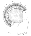
- La figure 4 représente, vu en coupe et partiellement écorché, un mode de réalisation d'une prothèse rotulienne comportant le perfectionnement à la réalisation selon les figures 1 à 3, et
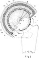
- La figure 5 représente, vu en coupe et partiellement écorché, un autre mode de réalisation d'une prothèse rotulienne selon l'invention.
- La prothèse rotulienne dont un mode de réalisation est illustré sur les figures 1 à 3 comporte au moins une coupelle 4 définissant un logement en creux sensiblement hémisphérique 5 d'un rayon de courbure "R" ayant une prière valeur, et au moins une portion de sphère 6 ayant une deuxième valeur de rayon de courbure "r", la deuxième valeur "r" étant inférieure à la prière valeur "R".
- La portion de sphère 6 est située dans le logement 5 de la coupelle 4 de façon que son centre "c" soit confondu avec celui "C" du logement, pour définir entre elle et ce logement un espace hémisphérique 12, des billes 7 étant disposées dans cet espace hémisphérique entre la paroi 9 du logement 5 et la paroi 10 de la portion de sphère 6.
- Les billes 7 ont un diamètre d'une troisiéme valeur égale à la différence entre lesdites première et deuxième valeurs de rayon de courbure de façon qu'elles soient au contact de la paroi 9 du logement et de la paroi 10 de la portion de sphère.
- Selon une caractéristique importante, la prothèse comporte en outre une cavité 40 réalisée dans la coupelle 4. Cette cavité 40 comporte une ouverture circulaire 41 la reliant à l'espace hémisphérique 12 définie sensiblement dans la paroi 9 du logement 5, avantageusement au niveau de son fond, et sensiblement centrée sur l'axe de révolution 43 de ce logement.
- Dans le mode de réalisation illustré, l'espace hémisphérique 12 et la cavité 40 sont remplis de billes 7 de façon que ces dernières y soient réparties sur une seule nappe et qu'elles soient au contact les unes des autres en au moins un point commun 44.
- Selon une caractéristique avantageuse, la largeur de l'ouverture circulaire 41 est sensiblement égale au diamètre des billes 7 en contact avec la paroi du logement et la portion de sphère.
- Dans une réalisation possible, l'épaisseur de la cavité 40 est égale au diamètre des billes 7. Cependant, pour favoriser le roulement de ces billes, cette épaisseur peut avantageusement être très légèrement supérieure à leur diamètre, comme représenté sur les figures.
- Bien entendu, a prothèse comporte des moyens 11 pour retenir les billes dans l'espace hémisphérique 12 et, selon une caractéristique du perfectionnement, les moyens 11 sont constitués par une bague 45 solidaire de la coupelle 4. La bague 45 a une configuration qui lui permet de border l'ouverture 41, en même temps que sa surface 46 tournée vers l'espace hémisphérique 12 forme une continuité avec la surface concave 47, la plus éloignée par rapport au logement 5, de la cavité 40.
- Dans un mode de réalisation avantageux, la cavité 40 est délimitée par deux pièces 51, 52 en forme de coupe placées l'une dans l'autre et formant, avec les moyens décrits ci-après permettant leur association, la coupelle 4.
- La coupe intérieure 52 est délimitée par deux prière 53 et seconde 54 surfaces respectivement concave et convexe, toutes deux essentiellement hémisphériques et concentriques, la prière surface concave 53 formant une partie de la paroi 9 du logement en creux 5.
- L'autre coupe 51 définit une troisième surface hémisphérique concave 55 ayant un rayon de courbure au moins égal, sinon très légèrement supérieur, à la somme du rayon de courbure de la seconde surface convexe 54 de la coupe intérieure 52 et du diamètre des billes 7 en contact avec les parois du logement et de la portion de sphère.
- Comme mentionné ci-avant, la coupelle 4 comporte des moyens 56 pour associer les deux coupes 51, 52 de façon que les trois prière 53, deuxième 54 et troisième 55 surfaces soient concentriques et que le bord 57 de la troisième surface, au niveau de l'ouverture circulaire 41 de la cavité 40, entoure la portion de paroi 58 reliant les deux prière 53 et deuxième 54 surfaces en restant éloignée de cette portion de paroi d'une distance au moins égale au diamètre des billes 7. Les moyens 56 pour associer les deux coupes 51, 52 sont avantageusement constitués par au moins une entretoise solidaire des deuxième et troisième surfaces. Cette entretoise, de préférence dépourvue de portions de contour aiguës, est par exemple de forme cylindrique de révolution.
- La prothèse décrite ci-dessus fonctionne de la façon suivante:
- On suppose par exemple que, par référence aux deux figures 1 et 2, la portion de sphère 6 subit une rotation senestrorsum 60. Dans ce cas, elle entraîne les billes 7 situées dans le logement 5, comme les billes 7-1, 7-2, ..., dans des rotations dextrorsum, par lesquelles elles glissent sur la surface 53 en tendant à pousser les billes 7-3, 7-4, ... qui sont dans la cavité 40, ou à son entrée, pour réalimenter l'espace hémisphérique 12 par la partie d'ouverture 41 opposée à celle par laquelle les billes 7 ont été envoyées dans la cavité 40.
- La rotation de la portion de sphère 6 est ainsi facilitée par le fait que certaines des billes ne sont plus obligées de frotter, dans une rotation sur elles-mêmes, contre le fond du logement en creux.
- Ce résultat est le même quelle que soit la rotation de la portion de sphère 6 par rapport à la coupelle 4, puisque l'ouverture 41 est circulaire et que les billes éjectées de l'espace 12 vers la cavité 40 sont automatiquement remplacées par des billes provenant de la cavité 40 et entrant dans l'espace 12 par la partie d'ouverture opposée à celle par laquelle les billes éjectées avaient quitté cet espace.
- Afin de réduire encore plus le frottement des billes, notamment dans la cavité 40, celle-ci a une épaisseur très légèrement supérieure au diamètre des billes, comme représenté sur les figures sur lesquelles cette différence a été exagérée à dessein.
- Dans ces conditions, la rotation des deux parties mâle et femelle de la prothèse rotulienne l'une par rapport à l'autre est obtenue avec un minimum de frottements, ce qui entraîne une importante réduction de la quantité produite de particules d'usure des matériaux en contact.
- La figure 4 représente un perfectionnement à la réalisation illustrée sur les figures 1 à 3.
- Dans le mode de réalisation illustré de ce perfectionnement, les billes emplissant le logement 5 et la cavité 40 (le logement 5 étant seul représenté par souci de simplification du dessin) sont constituées par une pluralité de premières billes sphériques 7 qui ont un diamètre "D" d'une valeur égale à la différence entre les première "R" et deuxième "r" valeurs de rayon de courbure et par une autre pluralité de secondes billes 37, ces secondes billes 37 ayant une quatrième valeur de diamètre "d" inférieure à la valeur "D" du diamètre des premières billes 7.
- Avantageusement, le nombre de secondes billes 37 est inférieur à celui des prières billes 7, de façon que la partie sphérique 6 de la prothèse soit bien supportée par les prières billes 7 de diamètre "D", alors que, en se répartissant et s'intercalant entre les billes 7, les secondes billes 37 de diamètre "d" permettent d'améliorer la rotation de ces prières billes. En effet, ces secondes billes 37 jouent en quelque sorte le rôle d'entretoises entre les billes 7, mais avec l'avantage que ces entretoises peuvent pivoter sur elles-mêmes.
- Le Demandeur a réalisé des prototypes de prothèse rotulienne selon l'invention qui ont donné satisfaction, dans lesquels le pourcentage de secondes billes 37 par rapport au nombre de prières billes 7 était de l'ordre de soixante à soixante-dix pour cent. Le logement 5 et la cavité 40 étaient entièrement remplis de billes 7 et 37 et les billes 37 de plus faible diamètre occupaient donc sensiblement trente-cinq pour cent du volume.
- Selon une autre caractéristique avantageuse additionnelle, comme illustré sur la figure 5 sur laquelle, comme pour l'exemple précédent par simple souci de simplification du dessin, la cavité 40 n'a pas été représentée, la coupelle 4 est constituée par un empilement d'au moins trois calottes 31, 32 et 33 les unes dans les autres, les deux calottes intérieure 31 et extérieure 33 étant réalisées en un matériau rigide, la calotte intermédiaire 32 étant réalisée en un matériau présentant une certaine élasticité de déformation, tel qu'un élastomère ou analogue.
- Par contre, la portion de sphère 6, les billes 7, 37 et la partie de coupelle 4 au contact des billes, par exemple la calotte intérieure 31, sont réalisées en un même matériau tel que, par exemple, un matériau à base de titane ou de mousse de titane.
- A cet empilement de trois calottes 31-33, sont associés des moyens 34 pour maintenir les trois calottes solidaires les unes des autres et éviter, par exemple, qu'elles ne pivotent les unes dans les autres ou qu'elles ne se désunissent. Ces moyens 34 sont très schématiquement représentés, sur la figure 5, par des ergots 35 ou analogue.
- Il est en outre avantageux que la valeur de l'angle au centre 14 du logement 5, comme illustré sur la figure 5, soit supérieure à 180 degrés, par exemple de façon que la portion 8 allant au-delà de l'angle plat, de cet angle au centre 14, contienne au moins une bille 7 de diamètre "D" .
- Bien évidemment, la valeur de l'angle au centre 15 de la portion de sphère 6 est supérieure à la valeur de l'angle au centre 14 du logement en creux pour que, comme dans toutes les prothèses rotuliennes et en particulier les prothèses coxo-fémorales, le mouvement de rotation de la partie mâle dans la partie femelle puisse avoir l'amplitude nécessairre pour la restitution des mouvements de l'articulation ainsi restaurée.
Claims (12)
- Prothèse rotulienne comportant :
au moins une coupelle (4) définissant un logement en creux hémisphérique (5) d'une prière valeur de rayon de courbure,
au moins une portion de sphère (6) ayant une deuxième valeur de rayon de courbure, cette dite deuxième valeur étant inférieure à ladite prière valeur,
une pluralité de premières billes sphériques (7) ayant un diamètre d'une troisième valeur égale à la différence entre lesdites prière et deuxième valeurs de rayon de courbure, ladite portion de sphère étant située dans ledit logement de la coupelle de façon que son centre et celui du logement soient confondus pour définir, entre elle et ledit logement, un espace hémisphérique (12), lesdites prières billes étant disposées dans ledit espace hémisphérique entre la paroi (9) dudit logement et la paroi (10) de ladite portion de sphère, et
des moyens (11) pour retenir lesdites billes dans ledit espace hémisphérique (12),
caractérisée par le fait qu'elle comporte en outre une cavité (40) réalisée dans ladite coupelle (4), ladite cavité comportant une ouverture circulaire (41) définie sensiblement dans la paroi (9) dudit logement (5) et sensiblement centrée sur l'axe de révolution (43) dudit logement, ladite ouverture reliant ledit espace hémisphérique (12) et ladite cavité (40). - Prothèse selon la revendication 1, caractérisée par le fait que la largeur de ladite ouverture (41) est sensiblement égale au diamètre desdites prières billes (7).
- Prothèse selon la revendication 2, caractérisée par le fait que l'épaisseur de ladite cavité (40) est légèrement supérieure audit diamètre desdites prières billes (7).
- Prothèse selon l'une des revendications précédentes, caractérisée par le fait que les moyens (11) pour retenir lesdites billes dans ledit espace hémisphérique (12) sont constitués par une bague (45) solidaire de ladite coupelle (4), ladite bague délimitant l'un des bords de ladite ouverture (41), la surface (46) de ladite bague tournée vers ledit espace hémisphérique (12) formant une continuité avec une surface (47,55) de ladite cavité.
- Prothèse selon l'une des revendications précédentes, caractérisée par le fait que ladite coupelle (4) est formée de deux pièces (51,52) en forme de coupes, l'une étant placée sensiblement dans l'autre, la coupe intérieure (52) étant délimitée par deux prière (53) et seconde (54) surfaces respectivement concave et convexe, toutes deux hémisphériques et concentriques, la prière surface concave (53) formant la paroi (9) du logement en creux (5), l'autre coupe (51) définissant une troisième surface hémisphérique (55) concave ayant un rayon de courbure au moins égal à la somme du rayon de courbure de la deuxième surface convexe (54) et du diamètre desdites prières billes (7), et de moyens (56) pour associer les deux dites coupes de façon que les trois prière, deuxième et troisième surfaces soient concentriques et que le bord de la troisième surface entoure la portion de paroi (58) reliant les deux prière (53) et deuxième (54) surfaces à une distance égale au moins au diamètre desdites prières billes.
- Prothèse selon la revendication 5, caractérisée par le fait que les moyens ( 56 ) pour associer les deux coupes sont constitués par au moins une entretoise solidaire des deuxième (54) et troisième (55) surfaces.
- Prothèse selon l'une des revendications précédentes, caractérisée par le fait qu'il comporte en outre une pluralité de secondes billes (37), lesdites secondes billes ayant une quatrième valeur de diamètre inférieure à ladite troisième valeur de diamètre des prières billes (7) et étant disposées dans ledit espace hémisphérique et ladite cavité.
- Prothèse selon la revendication 7, caractérisée par le fait que le nombre de secondes billes (37) est inférieur au nombre de permières billes (7).
- Prothèse selon l'une des revendications précédentes, caractérisée par le fait que ledit logement en creux (5) a une valeur d'angle au centre (14) supérieure à 180 degrés.
- Prothèse selon la revendication 9, caractérisée par le fait que la valeur de l'angle au centre (15) de la portion de sphère (6) est supérieure à la valeur de l'angle au centre (14) dudit logement en creux (5).
- Prothèse selon la revendication 10, caractérisée par le fait que la valeur de l'angle au centre (14) dudit logement en creux (5) est déterminée de façon que la portion (8), au-delà de l'angle plat, dudit angle au centre du logement en creux, contienne au moins une première bille (7).
- Prothèse selon l'une des revendications précédentes, caractérisée par le fait que ladite coupelle (4) est constituée par un empilement d'au moins trois calottes (31,32,33) les unes dans les autres, les deux calottes intérieure (31) et extérieure (33) étant réalisées en un matériau rigide, la calotte intermédiaire (32) étant réalisée en un matériau présentant une élasticité de déformation.
Applications Claiming Priority (6)
| Application Number | Priority Date | Filing Date | Title |
|---|---|---|---|
| FR9013017 | 1990-10-16 | ||
| FR9013017 | 1990-10-16 | ||
| FR9015345 | 1990-12-07 | ||
| FR9015345A FR2670107A1 (fr) | 1990-10-16 | 1990-12-07 | Prothese rotulienne. |
| FR9100279A FR2671483A1 (fr) | 1990-10-16 | 1991-01-11 | Prothese rotulienne. |
| FR9100279 | 1991-01-11 |
Publications (2)
| Publication Number | Publication Date |
|---|---|
| EP0481855A1 true EP0481855A1 (fr) | 1992-04-22 |
| EP0481855B1 EP0481855B1 (fr) | 1995-04-05 |
Family
ID=27252334
Family Applications (1)
| Application Number | Title | Priority Date | Filing Date |
|---|---|---|---|
| EP91402719A Expired - Lifetime EP0481855B1 (fr) | 1990-10-16 | 1991-10-11 | Prothèse d'articulation sphérique |
Country Status (3)
| Country | Link |
|---|---|
| EP (1) | EP0481855B1 (fr) |
| DE (1) | DE69108668T2 (fr) |
| ES (1) | ES2072571T3 (fr) |
Cited By (11)
| Publication number | Priority date | Publication date | Assignee | Title |
|---|---|---|---|---|
| EP0615733A1 (fr) * | 1993-03-15 | 1994-09-21 | AAP GmbH & Co. Betriebs KG | Articulation de substitution à billes |
| FR2705883A1 (fr) * | 1993-06-04 | 1994-12-09 | Revest Michel | Prothèse articulaire à roulement sphérique à billes. |
| WO1994029605A1 (fr) * | 1993-06-04 | 1994-12-22 | Michel Martial Revest | Dispositif d'articulation a roulement spherique a billes |
| EP0722703A3 (fr) * | 1995-01-21 | 1997-05-28 | Aldinger Guenther | Articulation artificielle, notamment une endoprothèse d'articulation de la hanche |
| RU2138226C1 (ru) * | 1998-08-11 | 1999-09-27 | Научно-исследовательский центр Татарстана "Восстановительная травматология и ортопедия" | Эндопротез тазобедренного сустава |
| RU2154445C2 (ru) * | 1998-10-13 | 2000-08-20 | Научно-исследовательский центр Татарстана "Восстановительная травматология и ортопедия" | Эндопротез тазобедренного сустава |
| RU2265420C1 (ru) * | 2004-03-18 | 2005-12-10 | Научно-исследовательский центр Татарстана "Восстановительная травматология и ортопедия" (НИЦТ "ВТО") | Эндопротез тазобедренного сустава |
| US7179298B2 (en) | 2005-05-27 | 2007-02-20 | Greenlee Wilfred E | Hip prosthesis and the use thereof |
| RU2408328C1 (ru) * | 2009-08-12 | 2011-01-10 | Государственное образовательное учреждение высшего профессионального образования "Тюменский государственный нефтегазовый университет" (филиал ТюмГНГУ "Тобольский индустриальный институт") | Эндопротез тазобедренного сустава |
| DE102012111365A1 (de) * | 2012-11-23 | 2014-05-28 | Dot Gmbh | Hüftgelenkendoprothesenkopf |
| CN104783932A (zh) * | 2015-05-08 | 2015-07-22 | 北京爱康宜诚医疗器材股份有限公司 | 髋臼假体 |
Citations (6)
| Publication number | Priority date | Publication date | Assignee | Title |
|---|---|---|---|---|
| DE2024583A1 (de) * | 1969-05-23 | 1970-11-26 | Osteo Ag, Selzach (Schweiz) | Hüftgelenkprothese |
| FR2060179A1 (fr) * | 1969-09-02 | 1971-06-18 | Cellier Michel | |
| US3683421A (en) * | 1970-07-13 | 1972-08-15 | Skf Ind Inc | Prosthetic joint assembly |
| FR2357235A1 (fr) * | 1976-07-05 | 1978-02-03 | Leveau Henri | Prothese de hanche |
| EP0066092A1 (fr) * | 1981-05-30 | 1982-12-08 | orthoplant Endoprothetik GmbH | Coussinet de prothèse pour l'acétabule d'une articulation de la hanche |
| EP0303195A1 (fr) * | 1987-08-13 | 1989-02-15 | Friedrichsfeld Aktiengesellschaft Keramik- und Kunststoffwerke | Endoprothèse d'articulation du genou |
-
1991
- 1991-10-11 DE DE69108668T patent/DE69108668T2/de not_active Expired - Fee Related
- 1991-10-11 EP EP91402719A patent/EP0481855B1/fr not_active Expired - Lifetime
- 1991-10-11 ES ES91402719T patent/ES2072571T3/es not_active Expired - Lifetime
Patent Citations (6)
| Publication number | Priority date | Publication date | Assignee | Title |
|---|---|---|---|---|
| DE2024583A1 (de) * | 1969-05-23 | 1970-11-26 | Osteo Ag, Selzach (Schweiz) | Hüftgelenkprothese |
| FR2060179A1 (fr) * | 1969-09-02 | 1971-06-18 | Cellier Michel | |
| US3683421A (en) * | 1970-07-13 | 1972-08-15 | Skf Ind Inc | Prosthetic joint assembly |
| FR2357235A1 (fr) * | 1976-07-05 | 1978-02-03 | Leveau Henri | Prothese de hanche |
| EP0066092A1 (fr) * | 1981-05-30 | 1982-12-08 | orthoplant Endoprothetik GmbH | Coussinet de prothèse pour l'acétabule d'une articulation de la hanche |
| EP0303195A1 (fr) * | 1987-08-13 | 1989-02-15 | Friedrichsfeld Aktiengesellschaft Keramik- und Kunststoffwerke | Endoprothèse d'articulation du genou |
Cited By (12)
| Publication number | Priority date | Publication date | Assignee | Title |
|---|---|---|---|---|
| EP0615733A1 (fr) * | 1993-03-15 | 1994-09-21 | AAP GmbH & Co. Betriebs KG | Articulation de substitution à billes |
| FR2705883A1 (fr) * | 1993-06-04 | 1994-12-09 | Revest Michel | Prothèse articulaire à roulement sphérique à billes. |
| WO1994029605A1 (fr) * | 1993-06-04 | 1994-12-22 | Michel Martial Revest | Dispositif d'articulation a roulement spherique a billes |
| EP0722703A3 (fr) * | 1995-01-21 | 1997-05-28 | Aldinger Guenther | Articulation artificielle, notamment une endoprothèse d'articulation de la hanche |
| RU2138226C1 (ru) * | 1998-08-11 | 1999-09-27 | Научно-исследовательский центр Татарстана "Восстановительная травматология и ортопедия" | Эндопротез тазобедренного сустава |
| RU2154445C2 (ru) * | 1998-10-13 | 2000-08-20 | Научно-исследовательский центр Татарстана "Восстановительная травматология и ортопедия" | Эндопротез тазобедренного сустава |
| RU2265420C1 (ru) * | 2004-03-18 | 2005-12-10 | Научно-исследовательский центр Татарстана "Восстановительная травматология и ортопедия" (НИЦТ "ВТО") | Эндопротез тазобедренного сустава |
| US7179298B2 (en) | 2005-05-27 | 2007-02-20 | Greenlee Wilfred E | Hip prosthesis and the use thereof |
| RU2408328C1 (ru) * | 2009-08-12 | 2011-01-10 | Государственное образовательное учреждение высшего профессионального образования "Тюменский государственный нефтегазовый университет" (филиал ТюмГНГУ "Тобольский индустриальный институт") | Эндопротез тазобедренного сустава |
| DE102012111365A1 (de) * | 2012-11-23 | 2014-05-28 | Dot Gmbh | Hüftgelenkendoprothesenkopf |
| WO2014079753A1 (fr) | 2012-11-23 | 2014-05-30 | Dot Gmbh | Tête d'endoprothèse d'articulation de la hanche |
| CN104783932A (zh) * | 2015-05-08 | 2015-07-22 | 北京爱康宜诚医疗器材股份有限公司 | 髋臼假体 |
Also Published As
| Publication number | Publication date |
|---|---|
| DE69108668T2 (de) | 1995-11-23 |
| DE69108668D1 (de) | 1995-05-11 |
| EP0481855B1 (fr) | 1995-04-05 |
| ES2072571T3 (es) | 1995-07-16 |
Similar Documents
| Publication | Publication Date | Title |
|---|---|---|
| EP0507645B1 (fr) | Prothèse médicale pour articulation | |
| EP1611872B1 (fr) | Prothèse d'épaule ou de hanche | |
| EP0461019B1 (fr) | Rotule pour prothèse | |
| EP0481855B1 (fr) | Prothèse d'articulation sphérique | |
| EP1229872B1 (fr) | Prothese cotyloidienne expansible a double mobilite | |
| EP0857472B1 (fr) | Prothèse totale de coude | |
| WO1999048442A1 (fr) | Lentille intraoculaire monobloc souple | |
| EP1781214B1 (fr) | Système d'implants à triple articulation du type sphérique pour membre supérieur ou inférieur | |
| WO2005046534A1 (fr) | Prothese totale de disque intervertebral | |
| WO2003047469A1 (fr) | Cotyle pour rotule de prothese de hanche ou analogue | |
| EP0821922A1 (fr) | Partie articulaire d'une prothèse de hanche avec piége à particules | |
| FR2649605A1 (fr) | Implant corneen | |
| FR2929103A1 (fr) | Prothese cotyloidienne du type dit "a double mobilite" | |
| EP1877011A1 (fr) | Prothese de disque intervertebral | |
| BE1006003A3 (fr) | Implant intra-oculaire, notamment du type intra-sacculaire. | |
| CH584031A5 (fr) | ||
| FR2786390A1 (fr) | Cotyle de correction pour emploi dans le traitement de pathologies de la hanche | |
| EP2276427A1 (fr) | Prothese d'articulation trapezo-metacarpienne | |
| WO1996000538A1 (fr) | Articulation prothetique du genou, notamment prothese unicompartimentale du genou, ou prothese de la rotule | |
| EP1053723B1 (fr) | Implant cotyloidien médialisé et à noyau mobile | |
| CA2586800C (fr) | Prothese acetabulaire destinee a etre fixee sans ciment | |
| FR2671483A1 (fr) | Prothese rotulienne. | |
| FR2817734A1 (fr) | Prothese intervertebrale | |
| FR2661605A1 (fr) | Cotyle pour prothese rotulienne notamment pour prothese du type coxo-femoral. | |
| FR2628967A1 (fr) | Prothese totale de la hanche |
Legal Events
| Date | Code | Title | Description |
|---|---|---|---|
| PUAI | Public reference made under article 153(3) epc to a published international application that has entered the european phase |
Free format text: ORIGINAL CODE: 0009012 |
|
| AK | Designated contracting states |
Kind code of ref document: A1 Designated state(s): BE CH DE ES FR GB IT LI |
|
| 17P | Request for examination filed |
Effective date: 19921006 |
|
| 17Q | First examination report despatched |
Effective date: 19940606 |
|
| GRAA | (expected) grant |
Free format text: ORIGINAL CODE: 0009210 |
|
| AK | Designated contracting states |
Kind code of ref document: B1 Designated state(s): BE CH DE ES FR GB IT LI |
|
| REF | Corresponds to: |
Ref document number: 69108668 Country of ref document: DE Date of ref document: 19950511 |
|
| ITF | It: translation for a ep patent filed | ||
| REG | Reference to a national code |
Ref country code: ES Ref legal event code: FG2A Ref document number: 2072571 Country of ref document: ES Kind code of ref document: T3 |
|
| GBT | Gb: translation of ep patent filed (gb section 77(6)(a)/1977) |
Effective date: 19950630 |
|
| PLBE | No opposition filed within time limit |
Free format text: ORIGINAL CODE: 0009261 |
|
| STAA | Information on the status of an ep patent application or granted ep patent |
Free format text: STATUS: NO OPPOSITION FILED WITHIN TIME LIMIT |
|
| 26N | No opposition filed | ||
| PGFP | Annual fee paid to national office [announced via postgrant information from national office to epo] |
Ref country code: GB Payment date: 19981001 Year of fee payment: 8 |
|
| PGFP | Annual fee paid to national office [announced via postgrant information from national office to epo] |
Ref country code: ES Payment date: 19981008 Year of fee payment: 8 |
|
| PGFP | Annual fee paid to national office [announced via postgrant information from national office to epo] |
Ref country code: CH Payment date: 19981106 Year of fee payment: 8 |
|
| PGFP | Annual fee paid to national office [announced via postgrant information from national office to epo] |
Ref country code: BE Payment date: 19981109 Year of fee payment: 8 |
|
| PGFP | Annual fee paid to national office [announced via postgrant information from national office to epo] |
Ref country code: DE Payment date: 19981204 Year of fee payment: 8 |
|
| PG25 | Lapsed in a contracting state [announced via postgrant information from national office to epo] |
Ref country code: GB Free format text: LAPSE BECAUSE OF NON-PAYMENT OF DUE FEES Effective date: 19991011 |
|
| PG25 | Lapsed in a contracting state [announced via postgrant information from national office to epo] |
Ref country code: ES Free format text: LAPSE BECAUSE OF NON-PAYMENT OF DUE FEES Effective date: 19991012 |
|
| PG25 | Lapsed in a contracting state [announced via postgrant information from national office to epo] |
Ref country code: LI Free format text: LAPSE BECAUSE OF NON-PAYMENT OF DUE FEES Effective date: 19991031 Ref country code: CH Free format text: LAPSE BECAUSE OF NON-PAYMENT OF DUE FEES Effective date: 19991031 Ref country code: BE Free format text: LAPSE BECAUSE OF NON-PAYMENT OF DUE FEES Effective date: 19991031 |
|
| BERE | Be: lapsed |
Owner name: BOUVET JEAN-CLAUDE Effective date: 19991031 |
|
| GBPC | Gb: european patent ceased through non-payment of renewal fee |
Effective date: 19991011 |
|
| REG | Reference to a national code |
Ref country code: CH Ref legal event code: PL |
|
| PG25 | Lapsed in a contracting state [announced via postgrant information from national office to epo] |
Ref country code: DE Free format text: LAPSE BECAUSE OF NON-PAYMENT OF DUE FEES Effective date: 20000801 |
|
| REG | Reference to a national code |
Ref country code: ES Ref legal event code: FD2A Effective date: 20001113 |
|
| PG25 | Lapsed in a contracting state [announced via postgrant information from national office to epo] |
Ref country code: IT Free format text: LAPSE BECAUSE OF NON-PAYMENT OF DUE FEES;WARNING: LAPSES OF ITALIAN PATENTS WITH EFFECTIVE DATE BEFORE 2007 MAY HAVE OCCURRED AT ANY TIME BEFORE 2007. THE CORRECT EFFECTIVE DATE MAY BE DIFFERENT FROM THE ONE RECORDED. Effective date: 20051011 |
|
| PGFP | Annual fee paid to national office [announced via postgrant information from national office to epo] |
Ref country code: FR Payment date: 20051017 Year of fee payment: 15 |
|
| REG | Reference to a national code |
Ref country code: FR Ref legal event code: ST Effective date: 20070629 |
|
| PG25 | Lapsed in a contracting state [announced via postgrant information from national office to epo] |
Ref country code: FR Free format text: LAPSE BECAUSE OF NON-PAYMENT OF DUE FEES Effective date: 20061031 |