EP0481914A1 - Stabilisation et positionnement de produits imprimés pendant leurs transport - Google Patents
Stabilisation et positionnement de produits imprimés pendant leurs transport Download PDFInfo
- Publication number
- EP0481914A1 EP0481914A1 EP91810673A EP91810673A EP0481914A1 EP 0481914 A1 EP0481914 A1 EP 0481914A1 EP 91810673 A EP91810673 A EP 91810673A EP 91810673 A EP91810673 A EP 91810673A EP 0481914 A1 EP0481914 A1 EP 0481914A1
- Authority
- EP
- European Patent Office
- Prior art keywords
- conveying
- printed product
- guide elements
- flow
- printed products
- Prior art date
- Legal status (The legal status is an assumption and is not a legal conclusion. Google has not performed a legal analysis and makes no representation as to the accuracy of the status listed.)
- Granted
Links
- 230000006641 stabilisation Effects 0.000 title description 6
- 238000011105 stabilization Methods 0.000 title description 6
- 238000000034 method Methods 0.000 claims abstract description 50
- 238000012545 processing Methods 0.000 claims abstract description 19
- 238000003780 insertion Methods 0.000 claims description 17
- 230000037431 insertion Effects 0.000 claims description 17
- 238000013459 approach Methods 0.000 claims description 4
- 230000000087 stabilizing effect Effects 0.000 claims description 4
- 238000013461 design Methods 0.000 description 3
- 238000007639 printing Methods 0.000 description 2
- 238000005452 bending Methods 0.000 description 1
- 238000011982 device technology Methods 0.000 description 1
- 230000000694 effects Effects 0.000 description 1
- 230000005484 gravity Effects 0.000 description 1
- 238000004519 manufacturing process Methods 0.000 description 1
- 230000000149 penetrating effect Effects 0.000 description 1
- 230000000630 rising effect Effects 0.000 description 1
Images



Classifications
-
- B—PERFORMING OPERATIONS; TRANSPORTING
- B65—CONVEYING; PACKING; STORING; HANDLING THIN OR FILAMENTARY MATERIAL
- B65H—HANDLING THIN OR FILAMENTARY MATERIAL, e.g. SHEETS, WEBS, CABLES
- B65H39/00—Associating, collating, or gathering articles or webs
- B65H39/02—Associating,collating or gathering articles from several sources
- B65H39/06—Associating,collating or gathering articles from several sources from delivery streams
- B65H39/065—Associating,collating or gathering articles from several sources from delivery streams by collecting in rotary carriers
-
- B—PERFORMING OPERATIONS; TRANSPORTING
- B65—CONVEYING; PACKING; STORING; HANDLING THIN OR FILAMENTARY MATERIAL
- B65H—HANDLING THIN OR FILAMENTARY MATERIAL, e.g. SHEETS, WEBS, CABLES
- B65H29/00—Delivering or advancing articles from machines; Advancing articles to or into piles
- B65H29/003—Delivering or advancing articles from machines; Advancing articles to or into piles by grippers
-
- B—PERFORMING OPERATIONS; TRANSPORTING
- B65—CONVEYING; PACKING; STORING; HANDLING THIN OR FILAMENTARY MATERIAL
- B65H—HANDLING THIN OR FILAMENTARY MATERIAL, e.g. SHEETS, WEBS, CABLES
- B65H2301/00—Handling processes for sheets or webs
- B65H2301/30—Orientation, displacement, position of the handled material
- B65H2301/32—Orientation of handled material
- B65H2301/323—Hanging
-
- B—PERFORMING OPERATIONS; TRANSPORTING
- B65—CONVEYING; PACKING; STORING; HANDLING THIN OR FILAMENTARY MATERIAL
- B65H—HANDLING THIN OR FILAMENTARY MATERIAL, e.g. SHEETS, WEBS, CABLES
- B65H2301/00—Handling processes for sheets or webs
- B65H2301/40—Type of handling process
- B65H2301/43—Gathering; Associating; Assembling
- B65H2301/434—In channels, e.g. in which the articles are substantially vertical or inclined
- B65H2301/4341—In channels, e.g. in which the articles are substantially vertical or inclined with several channels on a rotary carrier rotating around an axis parallel to the channels
-
- B—PERFORMING OPERATIONS; TRANSPORTING
- B65—CONVEYING; PACKING; STORING; HANDLING THIN OR FILAMENTARY MATERIAL
- B65H—HANDLING THIN OR FILAMENTARY MATERIAL, e.g. SHEETS, WEBS, CABLES
- B65H2301/00—Handling processes for sheets or webs
- B65H2301/40—Type of handling process
- B65H2301/44—Moving, forwarding, guiding material
- B65H2301/447—Moving, forwarding, guiding material transferring material between transport devices
- B65H2301/4471—Grippers, e.g. moved in paths enclosing an area
- B65H2301/44712—Grippers, e.g. moved in paths enclosing an area carried by chains or bands
-
- B—PERFORMING OPERATIONS; TRANSPORTING
- B65—CONVEYING; PACKING; STORING; HANDLING THIN OR FILAMENTARY MATERIAL
- B65H—HANDLING THIN OR FILAMENTARY MATERIAL, e.g. SHEETS, WEBS, CABLES
- B65H2301/00—Handling processes for sheets or webs
- B65H2301/40—Type of handling process
- B65H2301/44—Moving, forwarding, guiding material
- B65H2301/447—Moving, forwarding, guiding material transferring material between transport devices
- B65H2301/44765—Rotary transport devices with compartments
Definitions
- the invention relates to a method and a device according to the preambles of the independent claims for locally precise guidance and stabilization of, for example, suspended, flat objects, in particular printed products.
- Flat objects such as printed products are conveyed suspended in a conveying stream, in that a conveying means, for example a clamp or gripper, acts on the upper edge of each printed product.
- a conveying means for example a clamp or gripper
- the printed products are fed individually to any processing step by simply opening the conveying means with the force of gravity, while the conveying means continue to move essentially in a straight line.
- An application example for such a hanging feed to a processing step is the feed to a processing drum in which, for example, preliminary products and / or inserts are inserted into printed products.
- a corresponding device with a hanging feed is described in Swiss Patent No. 668 244 described by the same applicant. This patent specification is assumed to be known.
- the advantage of the hanging feeder is that the funding does not have to be carried out in the immediate vicinity of the feeder. As a result, the actual feed remains undisturbed and the funds can be directed away from the feed point in a simple manner.
- the hanging print product is fed with the lower edge ahead. This means that the precision of the feed depends on the positional accuracy of this lower edge.
- Such a feed is not a problem for sufficiently stiff, relatively slowly conveyed printed products, because the position of the lower edge is defined fairly precisely: it is always perpendicular to the upper edge. The supply can therefore be limited locally.
- the speed of this conveyor belt is equal to the conveying speed, the printed products will reach the feed point in a vertical position. If the speed of the conveyor belt is not exactly the same as the speed of the conveyor elements, the lower edge of the printed products is accelerated or decelerated relative to the upper edge and the printed products have a slightly inclined position at the feed point, which can be advantageous for the feed, for example to a processing drum .
- the position of an edge not held by the conveying means for example the lower edge of hanging printed products, relative to the edge held by the conveying means, for example the upper edge of hanging printed products, should be precisely defined and stable at a point on the conveying path.
- the method should be applicable in particular for flat, less stiff objects that are conveyed at high speed, so that they are not only moved out of their conveying position, for example hanging position, but also bent without stabilization by the air resistance.
- the process should be gentle on sensitive printed products by gradually moving them from the position deflected by the air resistance to the intended position.
- Another object of the invention is to provide an apparatus for performing the method. This should be straightforward, simple and robust.
- the basic principle of the method according to the invention is based on the fact that, in front of a positioning point at which, for example, the hanging print products of a conveying stream should have a very specific position, guide elements from above (ie from that side of the conveying stream at which the printed products are held by the conveying means) the flow is introduced so that the guide elements are moved up to the positioning point in the flow so that they gradually guide the printed products of the flow into the intended position, and that the guide elements are guided upwards out of the flow again after the positioning point.
- a guide element is assigned to each printed product.
- the guide elements move at constant distances from each other and at constant speed on a closed path, part of which runs within the flow.
- Figure 1 shows schematically a variant of the inventive method. It shows a flow of hanging printed products 11.1 / 2/3 ..., which are funded with funding 10.1 / 2/3 ...
- the conveying direction F is directed from right to left in the figure, the hanging printed products are at a distance a from one another, the conveying speed is v Fö .
- the printed products 11 are shown as solid lines in a real position caused by the air resistance and dashed lines in a vertical position which they would take up without air resistance.
- the aim of the method according to the invention is now to bring the printed products 11.1 / 2/3 ... at the positioning point P into an intended, precisely defined position, that is to say, for example, so inclined to the vertical that the lower edge is forward a distance d in the conveying direction the upper edge is the position in which the printed product 11.7 is shown.
- This is achieved by moving guide elements 12.1 / 2/3 ... in the conveying flow over part of the conveying path, specifically from the insertion point E in the conveying direction before the positioning point P to the exit point A after the positioning point P.
- the guide element 12.x is moved into the conveying stream at the point E between the printed product 11.x and the printed product 11.x-1 and passes through the conveying path to the delivery point A between these two printed products. So that there is no conflict with the conveying means 10.x at the insertion point E, it has a distance p from the printed product 11.x during the introduction, where p ⁇ a, preferably ⁇ a / 2. So that there is no conflict with the funding 10.x at the execution point A, it has the distance q from the printed product 11.x during the execution, where q ⁇ a, preferably ⁇ a / 2.
- the minimum sizes of p and q are determined by the design of the conveying means 10 and the guide elements 12.
- the means 10.1 and 10.11 are dashed in the figure (10.1 ', 10.11') also in shown the position they take at the time when the corresponding guide element 12.1 rsp. 12.11 in or out of the flow.
- the guide element 12.x moves on the one hand downwards and on the other hand in the conveying direction against a position relative to the printed product 11.x, that of the intended position of the printed product 11.x at the positioning point P corresponds. It reaches a position at the positioning point P which corresponds to the intended position of the printed product 11. X in the direction of conveyance. Towards the bottom, it is in a position relative to the lower edge in such a way that the lower edge has a defined position. Since the guide element 12.x approaches the printed product 11.x in the conveying direction from behind, that is to say against the air resistance, the printed product is driven by the air resistance against the guide element 12.x.
- the vertical distance l between the insertion point E and the lowest position of the guide elements 12 (12.7) corresponds approximately to the length of the printed products 11.
- a processing device is positioned below the conveying stream at this point on the conveying path, so that the guide elements 12 are advantageously moved upward out of the conveying stream. It is advantageous to delay them compared to the printed products 11 so that they are no longer carried.
- the guide element 12.x is thus moved over an execution path AS in such a way that it is decelerated in the conveying direction with respect to the printed product 11.x, and towards the top in such a way that it reaches the upper edge of the printed products 11 at the execution point A. Since the real positions of the printed product 11.x after the positioning point P depend on the specific application of the method according to the invention, the real positions of the printed products are 10.8 / 9/10/11 (solid lines), that is to say those printed products which the Positioning point P have already passed, not shown in the figure.
- the guide elements 12 are moved from the execution point A back to the insertion point E on any path.
- the entire length of the movement path of the guide elements 12 must be an integral multiple of the distance c between the guide elements 12.
- a method variant of the method shown in FIG. 1 is that the distance d is zero, that is to say that the intended position of the hanging printed products 11 at the positioning point P is a vertical one.
- d becomes negative, which represents a further process variant.
- the method according to the invention is shown in FIG. 1 on a straight, horizontally running conveyor line.
- the method according to the invention is in no way limited to straight, horizontal conveyor lines, but can also be used for rising, falling or curved conveyor lines.
- the path of movement of the guide elements 12 within the flow is shown as being composed of two straight lines. This is not a requirement for the method according to the invention. Trajectories from more than two straight lines and also with curved parts can be used. Curved trajectories are particularly advantageous in connection with conveyor lines that also do not run in a straight line. At points where the guide elements 12 change their direction of movement, for example at the positioning point P, it is advantageous for reasons of device technology to arrange a short, curved piece between the two straight parts of the movement path of the guide elements 12 (see device in FIG. 4).
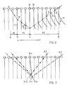
- FIG. 2 shows a variant of the method with a horizontal, straight-line conveying path and a movement path of the guide elements 12 composed of three straight-line parts.
- the guide elements 12 do not immediately lag behind the print products 11 assigned to them, but instead guide them over a guide path PS in the same position that they are at the positioning point P. achieved.
- An execution route AS then connects to the guide route PS.
- FIG. 3 shows a further method variant, which is advantageously used when the intended position of the printed products 11 at the positioning point P is approximately the same as that caused by the air resistance, so that the air resistance no longer presses the printed products 11 sufficiently against the guide elements 12, to guarantee safe guidance and stabilization.
- each printed product 11.x can be assigned two guide elements 12.x1 and 12.x2, the guide element 12.x1 (shown as a circle) moving on the movement path B.1 and moving in the conveying direction from the rear over the insertion path the printing product to be guided 11.x approaches, while the guide element 12.x2 (shown as a point) moves on the movement path B.2 and approaches the printing product to be guided 11.x from the front.
- the upper guide element prevents the printed product from bending backwards due to the air resistance between the bracket and the lower guide element, such that its lower edge is pressed backwards over the lower guide element.
- the movement paths of the lower and the upper guide elements for such an arrangement run parallel to one another.
- FIGS. 4 and 5 show a device for carrying out that process variant which was described in connection with FIG. 1.
- the device 40 according to the invention is shown in use together with a conveying device 50 for a conveying flow of hanging printed products, and a processing drum 60.
- the entire arrangement is seen in FIG. 4 from a direction parallel to the axis of the processing drum 60.
- FIG. 5 shows in detail a printed product 11.x with the corresponding conveyor clamp 10.x and the corresponding paired guide element 12.x, seen parallel to the conveying direction.
- the processing drum 60 and the conveyor device 50 are known from the above-mentioned CH patent 668 244.
- the use of the device according to the invention can be clearly seen from FIG .
- the printed products 11.1 / 2/3 ... are conveyed on brackets 10.1 / 2/3 ... against the processing drum 60 on a slightly sinking conveyor line, for example.
- the processing drum 60 rotates in the direction of the arrow and has compartments 61.1 / 2/3 ... into which the printed products 11.1 / 2/3 ... are to be fed.
- the printed product 11.6 is shown in the feed position. Its lower edge is already in the entrance of a corresponding one Compartment 61.6 of the processing drum 60 positioned.
- each printed product 11.x can be inserted exactly into compartment 61.x even at high conveying speed, its lower edge must be stable and in a defined position when it has reached the position which is assumed by printed product 11.6 in the figure be.
- the printed product 11.x is conveyed a little further after the feed point by the clamp 10.x, the lower edge penetrating ever deeper into the corresponding compartment 61.x of the processing drum 60. Only in the position in which the printed product 11.9 is shown does the clip 10.x open and the printed product 11.x falls into the compartment 61.x.
- Guide elements 12.1 / 2/3 ... are fastened at regular intervals on at least one traction means which is closed to the ring and is arranged laterally from the flow, preferably a chain 41 (indicated by a dash-dotted line) or a toothed belt.
- the chain runs over, for example, four sprockets 42.1 / 2/3/4, one of which is operatively connected to a drive (not visible in the figure), so that the sprockets 42.1 / 2/3/4 are in operation as indicated by the arrows Turn directions.
- the drive speed of the chain is matched to the conveying speed of the printed products in such a way that the guide elements cover the distance c in the same time as the printed products cover the distance a.
- the sprocket 42.2 is arranged at the positioning point (feed position) and effects the change in direction of the guide elements 12 which is necessary at this point.
- the sprockets 42.1 and 42.3 are above the conveyor path in the area of the ins.
- Execution point arranged, while the sprocket 42.4 is arranged in that part of the path of movement of the guide elements in which they move from the execution point back to the insertion point. For reasons of space, it is advantageous to drive the sprocket 42.4.
- FIG. 5 shows the arrangement of a guide element 12.x relative to a printed product 11.x, which is conveyed by a transport clamp 10.x.
- the viewing direction is in the conveying direction and parallel to the conveying direction, that is to say corresponding to the arrow V in FIG. 4.
- the bracket 10.x grips the printed product 11.x in the middle of its upper edge.
- a stabilizing bar 13.x is shown, which extends in width approximately over the middle half of the printed product. The less rigid the conveyed printed product is, the wider the stabilizing bar 13.x must be designed so that a defined position of the upper edge of the printed product in the conveying direction is guaranteed.
- the two parts 12.x r and 12.x l of the guide element 12.x are arranged on the left and the right side of the printed product 11.x. In this embodiment, they are rod-shaped and each extend over about a quarter of the width of the printed product 11.x. Furthermore, the two chains 41 r and 41 l are partially shown in the figure. The chain 41 r carries all the right parts of the guide elements 12, the chain 41 l all the left parts. The sprockets 42.2 r and 42.2 l are also visible in the figure. The illustrated guide element 12.x is located in the figure just below the sprockets 42.2, that is, approximately at the positioning point.
- the distance g between them must be at least as large as the width f of the driven part 51 of the conveying device 50 which carries the brackets 10.
- a further sprocket would have to be arranged between the sprockets 42.2 and 42.3, which causes the guide elements to change direction after the guide path PS.
- a further guide device which roughly corresponds to the guide device 40, would have to be arranged.
Landscapes
- Engineering & Computer Science (AREA)
- Mechanical Engineering (AREA)
- Discharge By Other Means (AREA)
- Feeding Of Articles By Means Other Than Belts Or Rollers (AREA)
- Handling Of Cut Paper (AREA)
- Specific Conveyance Elements (AREA)
- Registering Or Overturning Sheets (AREA)
- Organic Low-Molecular-Weight Compounds And Preparation Thereof (AREA)
- Steroid Compounds (AREA)
- Chain Conveyers (AREA)
Applications Claiming Priority (2)
| Application Number | Priority Date | Filing Date | Title |
|---|---|---|---|
| CH3350/90 | 1990-10-19 | ||
| CH335090 | 1990-10-19 |
Publications (2)
| Publication Number | Publication Date |
|---|---|
| EP0481914A1 true EP0481914A1 (fr) | 1992-04-22 |
| EP0481914B1 EP0481914B1 (fr) | 1995-05-10 |
Family
ID=4254077
Family Applications (1)
| Application Number | Title | Priority Date | Filing Date |
|---|---|---|---|
| EP91810673A Expired - Lifetime EP0481914B1 (fr) | 1990-10-19 | 1991-08-22 | Stabilisation et positionnement de produits imprimés pendant leurs transport |
Country Status (10)
| Country | Link |
|---|---|
| US (1) | US5169139A (fr) |
| EP (1) | EP0481914B1 (fr) |
| JP (1) | JP3048444B2 (fr) |
| AT (1) | ATE122318T1 (fr) |
| AU (1) | AU648815B2 (fr) |
| CA (1) | CA2051243C (fr) |
| DE (1) | DE59105432D1 (fr) |
| ES (1) | ES2075952T3 (fr) |
| FI (1) | FI105020B (fr) |
| RU (1) | RU2077469C1 (fr) |
Cited By (2)
| Publication number | Priority date | Publication date | Assignee | Title |
|---|---|---|---|---|
| EP1717179A1 (fr) * | 2005-04-29 | 2006-11-02 | Müller Martini Holding AG | Dispositif pour stabiliser des produits imprimés transportés en flux le long d'un trajet de transport, suspendus dans des pinces d'un dispositif de transport |
| US7784784B2 (en) | 2007-07-17 | 2010-08-31 | Mueller Martini Holding Ag | Method and apparatus for transferring printed products conveyed in an shingled flow to a transporter with circulating clamps |
Families Citing this family (14)
| Publication number | Priority date | Publication date | Assignee | Title |
|---|---|---|---|---|
| DE59200946D1 (de) * | 1991-06-10 | 1995-01-26 | Ferag Ag | Verfahren und Vorrichtung zum Öffnen und auf eine sattelförmige Auflage Ablegen von gefalteten Druckereiprodukten. |
| EP0522319B1 (fr) * | 1991-07-11 | 1995-02-01 | Ferag AG | Procédé et dispositif pour ouvrir des articles flexible pliés hors du centre |
| US5244203A (en) * | 1992-04-24 | 1993-09-14 | Eastman Kodak Company | Sheet transporting apparatus with a transport belt to which sheets are selectively clamped |
| ES2086852T3 (es) * | 1992-12-04 | 1996-07-01 | Ferag Ag | Procedimiento y dispositivo para abrir productos de imprenta plegados. |
| DE59405887D1 (de) * | 1993-10-08 | 1998-06-10 | Ferag Ag | Vorrichtung zum Oeffnen und Weitertransportieren von Druckereiprodukten |
| DK0676354T3 (da) * | 1994-04-08 | 2000-12-11 | Ferag Ag | Fremgangsmåde og indretning til emballering af trykte produkter |
| WO1996032351A1 (fr) * | 1995-04-11 | 1996-10-17 | Grapha-Holding Ag | Procede et dispositif pour transporter un flux de produits d'imprimerie |
| DE59608549D1 (de) * | 1995-07-11 | 2002-02-14 | Ferag Ag | Vorrichtung zum Beschneiden von gefalteten Druckereierzeugnissen, wie Zeitungen, Zeitschriften, Broschüren und dergleichen |
| AU745311B2 (en) * | 1997-09-18 | 2002-03-21 | Ipt Weinfelden Ag | Star feeder for transferring objects from a first conveying means to a second conveying means |
| PT1042206E (pt) * | 1997-12-23 | 2002-09-30 | Ferag Ag | Dispositivo para a recolha e/ou a entrega de produtos planos |
| CH693482A5 (de) * | 1998-12-24 | 2003-08-29 | Spuehl Ag St Gallen | Anlage zum Transport von schraubenlinienförmig gewundenen Federn. |
| ATE394332T1 (de) | 2003-12-22 | 2008-05-15 | Ferag Ag | Verfahren und vorrichtung zur stabilisierung und positionierung von flächigen gegenständen |
| EP1683612B1 (fr) * | 2005-01-21 | 2016-08-03 | Ferag AG | Procédé et dispositif pour transporter des produits plats flexibles, et pour les découper au même temps |
| DE502006004786D1 (de) * | 2006-03-14 | 2009-10-22 | Mueller Martini Holding Ag | Einrichtung zur Überführung von Druckprodukten |
Citations (3)
| Publication number | Priority date | Publication date | Assignee | Title |
|---|---|---|---|---|
| FR2247408A1 (fr) * | 1973-10-10 | 1975-05-09 | Ferag Ag | |
| GB2182025A (en) * | 1985-10-23 | 1987-05-07 | Ferag Ag | Method and apparatus for processing printed products |
| EP0305671A1 (fr) * | 1987-08-28 | 1989-03-08 | Ferag AG | Convoyeur pour des imprimés et application du convoyeur |
Family Cites Families (5)
| Publication number | Priority date | Publication date | Assignee | Title |
|---|---|---|---|---|
| US4448408A (en) * | 1981-06-04 | 1984-05-15 | Advance Enterprises, Inc. | Gripper clamps for conveying paper sheet products |
| CH668245A5 (de) * | 1985-09-27 | 1988-12-15 | Ferag Ag | Einrichtung zum zusammentragen unterschiedlicher druckprodukte. |
| CH669944A5 (fr) * | 1986-04-04 | 1989-04-28 | Ferag Ag | |
| DE3644423A1 (de) * | 1986-12-24 | 1988-07-07 | Roland Man Druckmasch | Einsteckvorrichtung, insbesondere fuer falzprodukte |
| US4921294A (en) * | 1988-06-03 | 1990-05-01 | Am International Incorporated | Spring wire gripper jaw |
-
1991
- 1991-08-22 EP EP91810673A patent/EP0481914B1/fr not_active Expired - Lifetime
- 1991-08-22 ES ES91810673T patent/ES2075952T3/es not_active Expired - Lifetime
- 1991-08-22 AT AT91810673T patent/ATE122318T1/de not_active IP Right Cessation
- 1991-08-22 DE DE59105432T patent/DE59105432D1/de not_active Expired - Lifetime
- 1991-08-27 AU AU82750/91A patent/AU648815B2/en not_active Ceased
- 1991-09-03 US US07/754,036 patent/US5169139A/en not_active Expired - Lifetime
- 1991-09-12 CA CA002051243A patent/CA2051243C/fr not_active Expired - Lifetime
- 1991-10-18 JP JP3271090A patent/JP3048444B2/ja not_active Expired - Lifetime
- 1991-10-18 RU SU915001854A patent/RU2077469C1/ru active
- 1991-10-18 FI FI914930A patent/FI105020B/fi active
Patent Citations (3)
| Publication number | Priority date | Publication date | Assignee | Title |
|---|---|---|---|---|
| FR2247408A1 (fr) * | 1973-10-10 | 1975-05-09 | Ferag Ag | |
| GB2182025A (en) * | 1985-10-23 | 1987-05-07 | Ferag Ag | Method and apparatus for processing printed products |
| EP0305671A1 (fr) * | 1987-08-28 | 1989-03-08 | Ferag AG | Convoyeur pour des imprimés et application du convoyeur |
Cited By (4)
| Publication number | Priority date | Publication date | Assignee | Title |
|---|---|---|---|---|
| EP1717179A1 (fr) * | 2005-04-29 | 2006-11-02 | Müller Martini Holding AG | Dispositif pour stabiliser des produits imprimés transportés en flux le long d'un trajet de transport, suspendus dans des pinces d'un dispositif de transport |
| US7637498B2 (en) | 2005-04-29 | 2009-12-29 | Müller Martini Holding AG | Apparatus for stabilizing printed products being transported in a containing stream over a distance hanging from clamps on a conveying device |
| US7784784B2 (en) | 2007-07-17 | 2010-08-31 | Mueller Martini Holding Ag | Method and apparatus for transferring printed products conveyed in an shingled flow to a transporter with circulating clamps |
| CN101407289B (zh) * | 2007-07-17 | 2013-01-23 | 米勒·马蒂尼控股公司 | 将导引的印刷品转送给具有夹子的运输机的方法和装置 |
Also Published As
| Publication number | Publication date |
|---|---|
| DE59105432D1 (de) | 1995-06-14 |
| US5169139A (en) | 1992-12-08 |
| CA2051243A1 (fr) | 1992-04-20 |
| FI914930A0 (fi) | 1991-10-18 |
| JP3048444B2 (ja) | 2000-06-05 |
| AU8275091A (en) | 1992-04-30 |
| ES2075952T3 (es) | 1995-10-16 |
| FI914930A7 (fi) | 1992-04-20 |
| AU648815B2 (en) | 1994-05-05 |
| FI105020B (fi) | 2000-05-31 |
| ATE122318T1 (de) | 1995-05-15 |
| RU2077469C1 (ru) | 1997-04-20 |
| JPH04333460A (ja) | 1992-11-20 |
| EP0481914B1 (fr) | 1995-05-10 |
| CA2051243C (fr) | 2002-02-19 |
Similar Documents
| Publication | Publication Date | Title |
|---|---|---|
| EP0481914B1 (fr) | Stabilisation et positionnement de produits imprimés pendant leurs transport | |
| DE10207073B4 (de) | Vorrichtung zum Transport von Bogen mit einem Bogenleitelement | |
| DE69305425T2 (de) | Vorrichtung zum Orientieren von auf einem Bandforderer angeführtes Geflügel mit dem Kopf in Forderrichtung | |
| EP0237701A1 (fr) | Procédé et dispositif pour l'insertion d'au moins un supplément dans des imprimés de préférence pliés | |
| AT396908B (de) | Vorrichtung zum verarbeiten von druckprodukten | |
| CH665410A5 (de) | Vorrichtung zum beschicken einer verarbeitungseinrichtung fuer biegsame, flaechige erzeugnisse, insbesondere druckprodukte. | |
| DE3003617C2 (de) | Vorrichtung zum Ausrichten von Fischen | |
| DE2530419C3 (de) | Förderer zum Transportieren von rechteckigen Metallplatten unterschiedlicher Größe | |
| EP1231176B1 (fr) | Dispositif pour alimenter des produits imprimés dans un canal de transport | |
| DE2749095A1 (de) | Vorrichtung zum oeffnen von druckprodukten | |
| WO2022218480A1 (fr) | Station de chargement pour un convoyeur aérien comprenant des poches de transport pour des marchandises à convoyer | |
| EP0062785B1 (fr) | Dispositif pour dévier du courant de transport des articles plats et flexibles, en particulier des articles imprimés | |
| DE102004023181B4 (de) | Zuführungsmaschine | |
| EP0499691A1 (fr) | Procédé pour traiter des produits imprimés alimentés de façon continue en une formation imbriquée ainsi que dispositif pour la mise en oeuvre dudit procédé | |
| EP4175902B1 (fr) | Procédé et dispositif de manipulation de produits (d'hygiène) | |
| EP0387726A2 (fr) | Dispositif de préhension, de stockage et de délivrance de produits pliés | |
| EP1219558B1 (fr) | Méthode et dispositif pour assembler des objects | |
| WO1999055609A1 (fr) | Procede et dispositif pour poursuivre l'acheminement d'objets plats arrivant dans un courant lamellaire | |
| DE3022972A1 (de) | Einrichtung zum vereinzelten zufuehren von rohren aus einem magazin zu einer abnahmestation o.dgl. | |
| CH646114A5 (de) | Vorrichtung zum vereinzeln eines stapels gefalteter oder gebundener, mehrblaettriger druckprodukte. | |
| CH684085A5 (de) | Verfahren zum Oeffnen von aussermittig gefalteten Druckereiprodukten und Vorrichtung zur Durchführung des Verfahrens. | |
| DE69100694T2 (de) | Vorrichtung zum Aufteilen von Gefässen auf eine einreihige Spur mit einer Übergabeplatte. | |
| DE3604095A1 (de) | Vorrichtung zum vereinzeln von brettern im quertransport | |
| DE1524504C3 (de) | Vorrichtung zum hochkant stehenden Stapeln von Aufzeichnungsträgern | |
| EP0675010A1 (fr) | Procédé et appareil pour le transport et la séparation du contenu d'enveloppes |
Legal Events
| Date | Code | Title | Description |
|---|---|---|---|
| PUAI | Public reference made under article 153(3) epc to a published international application that has entered the european phase |
Free format text: ORIGINAL CODE: 0009012 |
|
| AK | Designated contracting states |
Kind code of ref document: A1 Designated state(s): AT BE CH DE ES FR GB IT LI NL SE |
|
| 17P | Request for examination filed |
Effective date: 19920828 |
|
| 17Q | First examination report despatched |
Effective date: 19940707 |
|
| ITF | It: translation for a ep patent filed | ||
| GRAA | (expected) grant |
Free format text: ORIGINAL CODE: 0009210 |
|
| AK | Designated contracting states |
Kind code of ref document: B1 Designated state(s): AT BE CH DE ES FR GB IT LI NL SE |
|
| REF | Corresponds to: |
Ref document number: 122318 Country of ref document: AT Date of ref document: 19950515 Kind code of ref document: T |
|
| REF | Corresponds to: |
Ref document number: 59105432 Country of ref document: DE Date of ref document: 19950614 |
|
| ET | Fr: translation filed | ||
| GBT | Gb: translation of ep patent filed (gb section 77(6)(a)/1977) |
Effective date: 19950524 |
|
| REG | Reference to a national code |
Ref country code: ES Ref legal event code: FG2A Ref document number: 2075952 Country of ref document: ES Kind code of ref document: T3 |
|
| PLBE | No opposition filed within time limit |
Free format text: ORIGINAL CODE: 0009261 |
|
| STAA | Information on the status of an ep patent application or granted ep patent |
Free format text: STATUS: NO OPPOSITION FILED WITHIN TIME LIMIT |
|
| 26N | No opposition filed | ||
| PGFP | Annual fee paid to national office [announced via postgrant information from national office to epo] |
Ref country code: AT Payment date: 19970813 Year of fee payment: 7 Ref country code: BE Payment date: 19970813 Year of fee payment: 7 |
|
| PGFP | Annual fee paid to national office [announced via postgrant information from national office to epo] |
Ref country code: ES Payment date: 19970829 Year of fee payment: 7 |
|
| PGFP | Annual fee paid to national office [announced via postgrant information from national office to epo] |
Ref country code: NL Payment date: 19970831 Year of fee payment: 7 |
|
| PG25 | Lapsed in a contracting state [announced via postgrant information from national office to epo] |
Ref country code: AT Free format text: LAPSE BECAUSE OF NON-PAYMENT OF DUE FEES Effective date: 19980822 |
|
| PG25 | Lapsed in a contracting state [announced via postgrant information from national office to epo] |
Ref country code: ES Free format text: LAPSE BECAUSE OF EXPIRATION OF PROTECTION Effective date: 19980824 |
|
| PG25 | Lapsed in a contracting state [announced via postgrant information from national office to epo] |
Ref country code: BE Free format text: LAPSE BECAUSE OF NON-PAYMENT OF DUE FEES Effective date: 19980831 |
|
| BERE | Be: lapsed |
Owner name: FERAG A.G. Effective date: 19980831 |
|
| PG25 | Lapsed in a contracting state [announced via postgrant information from national office to epo] |
Ref country code: NL Free format text: LAPSE BECAUSE OF NON-PAYMENT OF DUE FEES Effective date: 19990301 |
|
| NLV4 | Nl: lapsed or anulled due to non-payment of the annual fee |
Effective date: 19990301 |
|
| REG | Reference to a national code |
Ref country code: ES Ref legal event code: FD2A Effective date: 20010201 |
|
| REG | Reference to a national code |
Ref country code: GB Ref legal event code: IF02 |
|
| REG | Reference to a national code |
Ref country code: CH Ref legal event code: PFA Owner name: FERAG AG Free format text: FERAG AG#ZUERICHSTRASSE 74#8340 HINWIL (CH) -TRANSFER TO- FERAG AG#PATENTABTEILUNG Z. H. MARKUS FELIX ZUERICHSTRASSE 74#8340 HINWIL (CH) |
|
| PGFP | Annual fee paid to national office [announced via postgrant information from national office to epo] |
Ref country code: GB Payment date: 20090827 Year of fee payment: 19 |
|
| PGFP | Annual fee paid to national office [announced via postgrant information from national office to epo] |
Ref country code: IT Payment date: 20090822 Year of fee payment: 19 |
|
| PGFP | Annual fee paid to national office [announced via postgrant information from national office to epo] |
Ref country code: CH Payment date: 20100818 Year of fee payment: 20 |
|
| PGFP | Annual fee paid to national office [announced via postgrant information from national office to epo] |
Ref country code: SE Payment date: 20100812 Year of fee payment: 20 Ref country code: DE Payment date: 20100823 Year of fee payment: 20 |
|
| GBPC | Gb: european patent ceased through non-payment of renewal fee |
Effective date: 20100822 |
|
| REG | Reference to a national code |
Ref country code: FR Ref legal event code: ST Effective date: 20110502 |
|
| PG25 | Lapsed in a contracting state [announced via postgrant information from national office to epo] |
Ref country code: IT Free format text: LAPSE BECAUSE OF NON-PAYMENT OF DUE FEES Effective date: 20100822 |
|
| PG25 | Lapsed in a contracting state [announced via postgrant information from national office to epo] |
Ref country code: FR Free format text: LAPSE BECAUSE OF NON-PAYMENT OF DUE FEES Effective date: 20100831 |
|
| REG | Reference to a national code |
Ref country code: DE Ref legal event code: R071 Ref document number: 59105432 Country of ref document: DE |
|
| REG | Reference to a national code |
Ref country code: DE Ref legal event code: R071 Ref document number: 59105432 Country of ref document: DE |
|
| PG25 | Lapsed in a contracting state [announced via postgrant information from national office to epo] |
Ref country code: GB Free format text: LAPSE BECAUSE OF NON-PAYMENT OF DUE FEES Effective date: 20100822 |
|
| REG | Reference to a national code |
Ref country code: CH Ref legal event code: PL |
|
| PGFP | Annual fee paid to national office [announced via postgrant information from national office to epo] |
Ref country code: FR Payment date: 20090914 Year of fee payment: 19 |
|
| REG | Reference to a national code |
Ref country code: SE Ref legal event code: EUG |
|
| PG25 | Lapsed in a contracting state [announced via postgrant information from national office to epo] |
Ref country code: DE Free format text: LAPSE BECAUSE OF EXPIRATION OF PROTECTION Effective date: 20110823 |