EP0481931A1 - Verbesserung eines Panikschlosssystems für einen Notausgang - Google Patents
Verbesserung eines Panikschlosssystems für einen Notausgang Download PDFInfo
- Publication number
- EP0481931A1 EP0481931A1 EP91830429A EP91830429A EP0481931A1 EP 0481931 A1 EP0481931 A1 EP 0481931A1 EP 91830429 A EP91830429 A EP 91830429A EP 91830429 A EP91830429 A EP 91830429A EP 0481931 A1 EP0481931 A1 EP 0481931A1
- Authority
- EP
- European Patent Office
- Prior art keywords
- semibar
- mobile
- improvement
- lever
- fixed
- Prior art date
- Legal status (The legal status is an assumption and is not a legal conclusion. Google has not performed a legal analysis and makes no representation as to the accuracy of the status listed.)
- Withdrawn
Links
- 230000002426 anti-panic effect Effects 0.000 title claims abstract description 19
- 230000006872 improvement Effects 0.000 title claims description 16
- 230000007246 mechanism Effects 0.000 claims abstract description 37
- 230000003213 activating effect Effects 0.000 claims abstract description 15
- 238000006073 displacement reaction Methods 0.000 claims description 11
- ZZUFCTLCJUWOSV-UHFFFAOYSA-N furosemide Chemical compound C1=C(Cl)C(S(=O)(=O)N)=CC(C(O)=O)=C1NCC1=CC=CO1 ZZUFCTLCJUWOSV-UHFFFAOYSA-N 0.000 claims description 10
- 230000005540 biological transmission Effects 0.000 claims description 4
- 238000007514 turning Methods 0.000 claims description 4
- 239000005557 antagonist Substances 0.000 claims description 3
- 239000002184 metal Substances 0.000 claims description 3
- GJJFMKBJSRMPLA-HIFRSBDPSA-N (1R,2S)-2-(aminomethyl)-N,N-diethyl-1-phenyl-1-cyclopropanecarboxamide Chemical compound C=1C=CC=CC=1[C@@]1(C(=O)N(CC)CC)C[C@@H]1CN GJJFMKBJSRMPLA-HIFRSBDPSA-N 0.000 claims 2
- 230000009471 action Effects 0.000 abstract description 5
- 230000004913 activation Effects 0.000 description 5
- 230000000903 blocking effect Effects 0.000 description 5
- 230000014759 maintenance of location Effects 0.000 description 5
- 230000008901 benefit Effects 0.000 description 4
- 238000007792 addition Methods 0.000 description 3
- 230000004888 barrier function Effects 0.000 description 2
- 238000010586 diagram Methods 0.000 description 2
- 229910000831 Steel Inorganic materials 0.000 description 1
- 238000005452 bending Methods 0.000 description 1
- 230000001447 compensatory effect Effects 0.000 description 1
- 238000010276 construction Methods 0.000 description 1
- 230000037431 insertion Effects 0.000 description 1
- 238000003780 insertion Methods 0.000 description 1
- 238000009434 installation Methods 0.000 description 1
- 230000002452 interceptive effect Effects 0.000 description 1
- 239000000463 material Substances 0.000 description 1
- 239000010959 steel Substances 0.000 description 1
Images
Classifications
-
- E—FIXED CONSTRUCTIONS
- E05—LOCKS; KEYS; WINDOW OR DOOR FITTINGS; SAFES
- E05B—LOCKS; ACCESSORIES THEREFOR; HANDCUFFS
- E05B65/00—Locks or fastenings for special use
- E05B65/10—Locks or fastenings for special use for panic or emergency doors
- E05B65/1046—Panic bars
- E05B65/1053—Panic bars sliding towards and away form the door
-
- E—FIXED CONSTRUCTIONS
- E05—LOCKS; KEYS; WINDOW OR DOOR FITTINGS; SAFES
- E05B—LOCKS; ACCESSORIES THEREFOR; HANDCUFFS
- E05B65/00—Locks or fastenings for special use
- E05B65/10—Locks or fastenings for special use for panic or emergency doors
- E05B65/1006—Locks or fastenings for special use for panic or emergency doors of the vertical rod type
-
- E—FIXED CONSTRUCTIONS
- E05—LOCKS; KEYS; WINDOW OR DOOR FITTINGS; SAFES
- E05B—LOCKS; ACCESSORIES THEREFOR; HANDCUFFS
- E05B65/00—Locks or fastenings for special use
- E05B65/10—Locks or fastenings for special use for panic or emergency doors
- E05B65/1093—Dogging means for holding the actuation means, e.g. the actuating handle
Definitions
- the invention relates to an improvement in an antipanic pushbar system, in particular the type which can be locked on the outside while remaining openable from the inside by simple manual action, without the need for a key.
- an antipanic pushbar system in particular the type which can be locked on the outside while remaining openable from the inside by simple manual action, without the need for a key.
- a typical configuration of such systems comprises the installation on one side of the door of a pressure-activated element which, when activated, produces the opening of the bolt of bolts, since frequently more than one of these is used, there often being one principal bolt and a number of secondary bolts.
- the invention refers to one of these typical configurations.
- the prior art embraces systems where the pressure-movable element is a moving barrier, held outwards from the door- front by arms fixed turnably to the door, so that the barrier moves up of down when leaned upon.
- the pressure-movable element is long, similar to a bar, and comprises a mobile outer semibar installed as a cover exteriorly over the fixed inner semibar and mechanically connected with said fixed semibar in such a way that when pressure is applied perpendicularly to the door, it produces an action on the lock which determines the simultaneaous retraction of the bolts.
- This concept is aesthetically attractive, modern and less complicated that the previously cited one.
- converting devices such as a caliper, which when pressure is applied to the mobile semibar, undergoes deformation and produces the longitudinal displacement of the tie bar which activates the opening of the lock.
- converting devices or calipers, comprise a first tract which has one end fixed to the mobile semibar and the other mounted articulatedly slidably to the fixed semibar, and a second tract which at one end is articulatedly fixed to the fixed semibar, and at the other end is articulated between the ends of said first tract.
- This positioning of the converting device operates in such a way that the displacement of the mobile semibar is not perfectly perpendicular to the door, since it describes a curved trajectory which is due to the horizontal stress generated in longitudinal direction on the bar by the deformation of the caliper of said converting device. It is thus necessity that between the mobile semibar and the box of the lock mechanism there exist a dimensional play which is able to absorb said horizontal stress, since the lock could not otherwise be activated.
- One of the drawbacks of this dimensional play is that coins and other objects can be inserted into it, thus blocking the functioning of the bar, with possibly tragic consequences in an emergency.
- a further drawback of this prior art device is that the existence of horizontal stress can make the pushbar mechanism perform badly when pressure is applied to one end of the bar, instead of in the middle of it; this is not a satisfactory situation.
- the present invention relates to a new concept for the converting mechanism for perpendicular pressure and the longitudinal displacement of the tie bar which produces the opening of the lock, wherein the trajectory of the mobile semibar is perfectly perpendicular to the door, avoiding the necessity of longitudinal play which is the cause of the drawbacks inherent in the above-described prior art devices.
- the fixed and mobile semibars are mechanically connected by at least one pair of identical tilting mechanisms, each comprising a single lever of rigid angular forme which at its summit is mounted tiltingly about a suspended axis situated between said fixed an mobile semibars and which angled lever is immobilised with respect to the fixed semibar, having a superior arm whose extremity is fixed to the mobile semibar with the possibility only of longitudinal displacement along said mobile semibar and having an inferior arm which is installed rotatably about a pivot which pivot crosses a longitudinal tie bar whose end is tractionably connected to the activating member of the bolt opening mechanism, said tie bar having a longitudinal guide which in the displacement direction of the mobile semibar has a dimensional play greater than the distance in radial direction defined by the curved trajectory discribed by the extremity of said lower arm of the angled lever.
- An important advantage of the present invention consists in the fact that the horizontal stress generated by the upper arm during the tilting of the angle lever is absorbed by the displacement ability of the end of the said upper arm of the angled lever with respect to the mobile arm to which it is connected; thus the displacement of said mobile semibar is perfectly straight and can be realised without significant play, avoiding the need to include slots into which coins and other blocking objects could be inserted to disrupt the antipanic emergency function. At the same time, the functional equilibrium of the bar and its activation is correct, even when application of pressure is not central.
- Another advantage of the present invention is that it is very simple and economical, both with respect to the number of parts needed to construct it and with respect to its construction.
- this mechanism comprises a discoid lever which, travelling with the mobile semibar and being activatable externally using an appropriate tool (namely, a key), is able to turn in a plane which is transversal to the operative movement of the mobile semibar, producing an active position in which with the mobile semibar in the open position, the discoid lever is enserted into a retaining niche cut into a wall envisaged in the fixed semibar, and another position, the non-active position, with the edge of the discoid lever retracted with respect to the said wall, said wall having above said niche another hole, or slot, which interferes with the said discoid lever, bringing it back into the non-active position if it should be accidentally locked into the active position before pressure is applied to the mobile semibar; on such first pressure being applied to the mobile semibar, therefore, the
- the activating member is connected to a sliding plate guided longitudinally inside and along the fixed semibar; said sliding plate is connected to the fixed structure of the principal lock by means of an extendable spring and has a hooking support for the end of a principal bolt mounted pendulously and activatably against an antagonist spring which is connected to said principal bolt end by means of an rotatable articulation situation below and in front of the tilting axis which the bolt has with respect to the said lock structure; said sliding plate being equipped with tabs which during its longitudinal retraction travel tangentially and push against peripherical protruberances on the rotatable neck envisaged as a means of operative interrelation with other elements of the lock system, such as handles of knobs and transmission bars for the activation of secondary bolts.
- the bolt has an open cavity in which a retractable equaliser is mounted and moves against an impulse spring having a hole through which a tilting pivot passes (with play) which pivot is fixed to the said bolt below said end joint and behind the axis of the said impulse spring lodged in it.
- Said equaliser has a shape which protrudes further that the bolt towards the exterior of the door, and an extra heel which when the equaliser tilts, comes up against an endstop envisaged in the neck, thus preventing the bolt from retracting when an impulse is received from outside the door. This prevents the lock from being violated by the introduction of a plastic card or similar through the splace between the door and the wall, since any impulse from that direction will only cause the blocking of the bolt. This blocking can only be released when pressure is applied to the pushbar inside the door, as the mechanism will then free the equaliser heel from the endstop by turning the neck; obviously the bolt is then also freed.
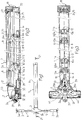
- figure 1 shows a mechanism for activating a locking system comprising in general a principal locking mechanism 2 with a principal bolt 2a, connected to a pushbar 1, with the possibility of other, secondary bolts (3a) which are activated by means of transmission bars 4 and 5 across the secondary locking mechanisms 3 which can comprise inversion devices for the impulse of the transmission bars 4 and 5.
- the pushbar 1 comprises (fig.2) the two semibars 1a and 1b.
- the inner or fixed semibar 1a of u-shaped metal, is mounted directly on the door and functions as a support for the activating device of the principal locking mechanism 2.
- the outer of mobile semibar 1b generally has a u-shaped profile and is mounted like a cover on to the inner semibar 1b, overlapping it externally, and has threaded cavities for the fixing of end pieces, such as for example the longitudinal rods 18 which help to absorb the horizontal stress 15 of the operational tilting of the angled levers 6 and which permit the slideable mounting of the mobile semibar 1b with respect to the pivots 8 thus enabling the exterior of the mobile semibar 1b to remain completely smooth, since it is not necessary for it to be a support for screws of other fixing elements for the internal mechanism.
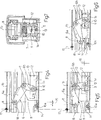
- the converting device for changing perpendicular pressure on the pushbar 1 into longitudinal action which produces the opening of the principal locking mechanism comprises angled levers 6, made in single rigid pieces, made of steel pressed into u-shape (figs 3 and 7) and with a variable configuration depending on each single case, in this particular configuration its being considered best that the internal angle should be slightly obtuse and that the operative dimension (distance between axes) of the upper arm 6a and lower arm 6b should be two to one in favour of the former.
- the pivot 8 constitutes the rotating articulation of the end of the uper arm 6a and has its guided ends in the longitudinal slots 18 of the mobile semibar 1b, so that the sliding of the pivot 8 in the longitudinal slots 18 allows the movement of the mobile semibar 1b to be perfectly perpendicularly straight with respect to the door, there being thus no displacement in longitudinal direction which can be disturbed and blocked by means of coins etc.
- the pivot 9 constitutes the rotating articulation of the lower arm 6b and crosses the base plate 13 of the tie bar 13 which acts on the activating member 14 of the lock 2.
- the tilting of the angled levers 6 is produced around the axis 7 on which it is rotatably mounted; said axis 7 is held in place by a u-shaped column 11 made of double-sheet metal and forming part of the baseplate 10 which is mounted to the bottom of the fixed semibar 1a, supporting the entire configuration.
- Figs. 4 to 6 show clearly the functioning of this new concept, according to which, on pressing on the mobile semibar 1b, said semibar 1b gives way because the tilting of the angled lever 6 is produced and, simultaneously a longitudinal displacement of the tiebar 13 which pulls the activating member 14.
- the said tilting makes the pivot 8 and 9 describe curved trajectories which describe respectively maximum radial amplitudes 15 and 16; radial amplitude 15 is the above-mentioned horizontal stress and it is explained above how this stress is absorbed so as not to affect the straight movement of the mobile semibar 1b; the other radial amplitude 16 is absorbed because the tiebar 13 is guided between the endpieces 12 which are created by bending of the baseplate 10 and that form an open canal that allows the tie bar 13 the necessary compensatory play, which play is also tolerated by the free connection that the said tie bar 13 has with the activating member 14 of the locking mechanism 2.
- the straightness of the linear movement of the mobile semibar 1b can be seen in figures 4 to 6, where the imaginary straight line travelled by the mark 17 (included solely for this purpose) is indicated.
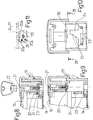
- the retaining mechanism 19 of the pushbar 1 in open position is positioned (figs 8 to 11) between the ends of the non-lock end of the fixed semibar 1a and the mobile semibar 1b.
- the discoid lever 20 is fixed to the mobile semibar 1b, being mounted on an axis that can be turned by activating the key 22 on the head 21 of the axis, so that in the unturned position (fig. 9) the edge of the lever 20 is displaced against the wall 24 connected to the fixed semibar 1a; on the other hand, if the pushbar 1 is pushed in, and the lever 20 is turned, a part of said lever 20 lodges in a small window 23 in said wall 24, holding the entire mechanism in this way in an open position.
- lever 20 should be turned to the active position before the puwhbar 1 is pushed, then the first time it is pushed the edge of the lever 20 will be interfered with by the lever-hole 25 cut into the edge of the wall 24, with the result that the lever 20 will pass into the non-active position.
- the two positions mentioned for the lever 20 are held by means of an anti-spring ball bearing 26 which is positioned above one of other of the orifices 20a in said lever 20.
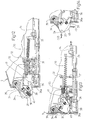
- Figure 14 shows he anti-retraction security of the bolt 2a when a frontal impulse 43 is placed on it; or possibly not frontal, but a force which is directly placed on it, and which has been preceded by a tangential impulse 42 as would be produced by the insertion at the edge of a plastic card, with the intention of opening the door from the exterior; thus, as the card reaches the edge 40 of the retractable equaliser 37 to which the impulse spring 38 is mounted, the equaliser 37 turns on the pivot 39 and places its heel 41 in the condition of interfering with the neck 36.
- the emergency action will not be inhibited by this event, since when the the mobile semibar 1b is activated, the tabs 29a will produce the turn ing of the neck 36 and the consequent retraction of the endstop 36a, as has already been explained.
Landscapes
- Business, Economics & Management (AREA)
- Emergency Management (AREA)
- Lock And Its Accessories (AREA)
Applications Claiming Priority (2)
| Application Number | Priority Date | Filing Date | Title |
|---|---|---|---|
| ES9002589A ES2031743A6 (es) | 1990-10-15 | 1990-10-15 | Perfeccionamientos en un sistema de cierre antipanico para puertas de emergencia. |
| ES9002589 | 1990-10-15 |
Publications (1)
| Publication Number | Publication Date |
|---|---|
| EP0481931A1 true EP0481931A1 (de) | 1992-04-22 |
Family
ID=8269153
Family Applications (1)
| Application Number | Title | Priority Date | Filing Date |
|---|---|---|---|
| EP91830429A Withdrawn EP0481931A1 (de) | 1990-10-15 | 1991-10-14 | Verbesserung eines Panikschlosssystems für einen Notausgang |
Country Status (2)
| Country | Link |
|---|---|
| EP (1) | EP0481931A1 (de) |
| ES (1) | ES2031743A6 (de) |
Cited By (15)
| Publication number | Priority date | Publication date | Assignee | Title |
|---|---|---|---|---|
| GB2284445A (en) * | 1994-11-07 | 1995-06-07 | Int Door Closers Inc | Panic exit door mechanism |
| US6000733A (en) * | 1997-09-25 | 1999-12-14 | International Door Closers, Inc. | Presser bar mechanism |
| EP1106758A1 (de) * | 1999-12-10 | 2001-06-13 | Costruzioni Italiane Serrature Affini C.I.S.A. S.p.A. | Panikstange |
| EP1050642A3 (de) * | 1999-05-05 | 2002-04-03 | Talleres De Escoriaza, S.A. | Antipanik-Schliesssystem |
| FR2818303A1 (fr) * | 2000-12-20 | 2002-06-21 | Metalux | Serrure anti-panique adaptable |
| EP1770232A1 (de) * | 2005-09-30 | 2007-04-04 | SAVIO S.p.A. | Steuerungssystem für Paniktüren |
| EP1070185A4 (de) * | 1998-04-07 | 2007-11-07 | Detex Corp | Panikausgang |
| EP1748129A3 (de) * | 2005-07-26 | 2010-04-28 | Talleres De Escoriaza, S.A. | Vorrichtung für ein Antipanikschließsystem, das für Nottüren bestimmt ist |
| EP2993287A1 (de) * | 2014-09-05 | 2016-03-09 | BKS GmbH | Druckstange zur Betätigung eines Türverschlusses |
| US20160115719A1 (en) * | 2014-10-23 | 2016-04-28 | Schlage Lock Company Llc | Windstorm damper device |
| US20190161993A1 (en) * | 2017-11-29 | 2019-05-30 | Hanchett Entry Systems, Inc. | Interchangeable Latch Assembly for an Exit Device |
| US20220018162A1 (en) * | 2019-01-28 | 2022-01-20 | Sargent Manufacturing Company | Universal dogging and electronic latch retraction |
| US11434666B2 (en) * | 2019-08-26 | 2022-09-06 | Well Laud Manufacturing Corp. | Anti-theft door lock assembly |
| EP4610458A1 (de) * | 2024-02-29 | 2025-09-03 | ASSA ABLOY Sicherheitstechnik GmbH | Anti-panik-druckstange mit türöffner |
| US12540489B2 (en) | 2021-02-04 | 2026-02-03 | Assa Abloy Access And Egress Hardware Group, Inc. | Universal electronic latch retraction mechanism |
Families Citing this family (1)
| Publication number | Priority date | Publication date | Assignee | Title |
|---|---|---|---|---|
| ES2122820B1 (es) * | 1994-08-01 | 1999-07-01 | Talleres Escoriaza Sa | Accionamiento perfeccionado de pestillos, en barras antipanico para puertas de emergencia. |
Citations (5)
| Publication number | Priority date | Publication date | Assignee | Title |
|---|---|---|---|---|
| US3663047A (en) * | 1970-08-05 | 1972-05-16 | Von Duprin Inc | Right-line movement panic exit device |
| US4083590A (en) * | 1977-02-02 | 1978-04-11 | Adams Rite Manufacturing Co. | Narrow stile panic exit actuator |
| EP0307088A1 (de) * | 1987-08-07 | 1989-03-15 | Yale Security Inc | Paniktürschloss |
| US4839988A (en) * | 1988-04-06 | 1989-06-20 | Thomas Industries Inc. | Panic exit device |
| US5011199A (en) * | 1989-12-28 | 1991-04-30 | Von Duprin, Inc. | Panic exit device having an exit-delaying mechanism |
-
1990
- 1990-10-15 ES ES9002589A patent/ES2031743A6/es not_active Expired - Lifetime
-
1991
- 1991-10-14 EP EP91830429A patent/EP0481931A1/de not_active Withdrawn
Patent Citations (5)
| Publication number | Priority date | Publication date | Assignee | Title |
|---|---|---|---|---|
| US3663047A (en) * | 1970-08-05 | 1972-05-16 | Von Duprin Inc | Right-line movement panic exit device |
| US4083590A (en) * | 1977-02-02 | 1978-04-11 | Adams Rite Manufacturing Co. | Narrow stile panic exit actuator |
| EP0307088A1 (de) * | 1987-08-07 | 1989-03-15 | Yale Security Inc | Paniktürschloss |
| US4839988A (en) * | 1988-04-06 | 1989-06-20 | Thomas Industries Inc. | Panic exit device |
| US5011199A (en) * | 1989-12-28 | 1991-04-30 | Von Duprin, Inc. | Panic exit device having an exit-delaying mechanism |
Cited By (23)
| Publication number | Priority date | Publication date | Assignee | Title |
|---|---|---|---|---|
| GB2284445A (en) * | 1994-11-07 | 1995-06-07 | Int Door Closers Inc | Panic exit door mechanism |
| US6000733A (en) * | 1997-09-25 | 1999-12-14 | International Door Closers, Inc. | Presser bar mechanism |
| EP1070185A4 (de) * | 1998-04-07 | 2007-11-07 | Detex Corp | Panikausgang |
| EP1050642A3 (de) * | 1999-05-05 | 2002-04-03 | Talleres De Escoriaza, S.A. | Antipanik-Schliesssystem |
| EP1106758A1 (de) * | 1999-12-10 | 2001-06-13 | Costruzioni Italiane Serrature Affini C.I.S.A. S.p.A. | Panikstange |
| FR2818303A1 (fr) * | 2000-12-20 | 2002-06-21 | Metalux | Serrure anti-panique adaptable |
| WO2002050392A1 (fr) * | 2000-12-20 | 2002-06-27 | Metalux | Serrure anti-panique adaptable |
| EP1748129A3 (de) * | 2005-07-26 | 2010-04-28 | Talleres De Escoriaza, S.A. | Vorrichtung für ein Antipanikschließsystem, das für Nottüren bestimmt ist |
| EP1770232A1 (de) * | 2005-09-30 | 2007-04-04 | SAVIO S.p.A. | Steuerungssystem für Paniktüren |
| US7731248B2 (en) | 2005-09-30 | 2010-06-08 | Savio Spa | Anti-panic control device for doors |
| EP2993287A1 (de) * | 2014-09-05 | 2016-03-09 | BKS GmbH | Druckstange zur Betätigung eines Türverschlusses |
| US20160115719A1 (en) * | 2014-10-23 | 2016-04-28 | Schlage Lock Company Llc | Windstorm damper device |
| US10030411B2 (en) * | 2014-10-23 | 2018-07-24 | Schlage Lock Company Llc | Windstorm damper device |
| US20190161993A1 (en) * | 2017-11-29 | 2019-05-30 | Hanchett Entry Systems, Inc. | Interchangeable Latch Assembly for an Exit Device |
| US11566449B2 (en) * | 2017-11-29 | 2023-01-31 | Hanchett Entry Systems, Inc. | Interchangeable latch assembly for an exit device |
| US20230151645A1 (en) * | 2017-11-29 | 2023-05-18 | Hanchett Entry Systems, Inc. | Interchangeable Latch Assembly for an Exit Device |
| US12366092B2 (en) | 2017-11-29 | 2025-07-22 | Hanchett Entry Systems, Inc. | Interchangeable latch assembly for an exit device |
| US20220018162A1 (en) * | 2019-01-28 | 2022-01-20 | Sargent Manufacturing Company | Universal dogging and electronic latch retraction |
| US12006735B2 (en) | 2019-01-28 | 2024-06-11 | Sargent Manufacturing Company | Universal dogging and electronic latch retraction |
| US12071789B2 (en) * | 2019-01-28 | 2024-08-27 | Sargent Manufacturing Company | Universal dogging and electronic latch retraction |
| US11434666B2 (en) * | 2019-08-26 | 2022-09-06 | Well Laud Manufacturing Corp. | Anti-theft door lock assembly |
| US12540489B2 (en) | 2021-02-04 | 2026-02-03 | Assa Abloy Access And Egress Hardware Group, Inc. | Universal electronic latch retraction mechanism |
| EP4610458A1 (de) * | 2024-02-29 | 2025-09-03 | ASSA ABLOY Sicherheitstechnik GmbH | Anti-panik-druckstange mit türöffner |
Also Published As
| Publication number | Publication date |
|---|---|
| ES2031743A6 (es) | 1992-12-16 |
Similar Documents
| Publication | Publication Date | Title |
|---|---|---|
| EP0481931A1 (de) | Verbesserung eines Panikschlosssystems für einen Notausgang | |
| CA2306427C (en) | Inner door handle for automobiles | |
| CA2144718C (en) | Deadbolt with infinitely adjustable backset | |
| US20040026932A1 (en) | Sash lock | |
| KR101019314B1 (ko) | 스테이 | |
| JP5318414B2 (ja) | ラッチ | |
| US4215884A (en) | Touch latch | |
| US7472514B2 (en) | Window, door or the like comprising a swinging arms assembly with stop means | |
| US5732986A (en) | Door lock | |
| CA2340591C (en) | Safety-lock for multi-position window | |
| EP0509063B1 (de) | Türfeststeller | |
| US6139072A (en) | Push-pull door lock | |
| KR200186315Y1 (ko) | 미닫이창의 잠금장치 | |
| US4822084A (en) | Sliding door lock assembly | |
| US6183023B1 (en) | Door with integrated fire exit device | |
| JP3569960B2 (ja) | 自動販売機のドアロック装置 | |
| WO1999057396A1 (en) | Security locking mechanism | |
| KR101545787B1 (ko) | 도어의 안전장치 | |
| HU223550B1 (hu) | Zárószerkezet, különösen zár ablakszárnyba vagy hasonlóba való beépítésre | |
| KR100256788B1 (ko) | 현금 자동 지급기의 도어 잠금장치 | |
| WO2000004260A1 (fr) | Poignee antivol | |
| JP3255613B2 (ja) | ロック機能を備えたスライドラッチ | |
| WO1999004118A1 (en) | A locking arrangement for sliding doors or shutters | |
| JPH09287333A (ja) | 引き戸用錠前 | |
| JPS6146136Y2 (de) |
Legal Events
| Date | Code | Title | Description |
|---|---|---|---|
| PUAI | Public reference made under article 153(3) epc to a published international application that has entered the european phase |
Free format text: ORIGINAL CODE: 0009012 |
|
| AK | Designated contracting states |
Kind code of ref document: A1 Designated state(s): DE FR GB IT |
|
| 17P | Request for examination filed |
Effective date: 19920922 |
|
| 17Q | First examination report despatched |
Effective date: 19931108 |
|
| STAA | Information on the status of an ep patent application or granted ep patent |
Free format text: STATUS: THE APPLICATION IS DEEMED TO BE WITHDRAWN |
|
| 18D | Application deemed to be withdrawn |
Effective date: 19940321 |