EP0481969B1 - Ladenregal - Google Patents
Ladenregal Download PDFInfo
- Publication number
- EP0481969B1 EP0481969B1 EP92200169A EP92200169A EP0481969B1 EP 0481969 B1 EP0481969 B1 EP 0481969B1 EP 92200169 A EP92200169 A EP 92200169A EP 92200169 A EP92200169 A EP 92200169A EP 0481969 B1 EP0481969 B1 EP 0481969B1
- Authority
- EP
- European Patent Office
- Prior art keywords
- rack
- shelves
- uprights
- shop
- movable
- Prior art date
- Legal status (The legal status is an assumption and is not a legal conclusion. Google has not performed a legal analysis and makes no representation as to the accuracy of the status listed.)
- Expired - Lifetime
Links
- 238000001514 detection method Methods 0.000 claims 2
- 239000000969 carrier Substances 0.000 description 13
- 238000000034 method Methods 0.000 description 9
- 238000009966 trimming Methods 0.000 description 5
- 230000000694 effects Effects 0.000 description 4
- 235000000346 sugar Nutrition 0.000 description 4
- 230000004048 modification Effects 0.000 description 3
- 238000012986 modification Methods 0.000 description 3
- 239000004033 plastic Substances 0.000 description 3
- 229920003023 plastic Polymers 0.000 description 3
- 238000010276 construction Methods 0.000 description 2
- 230000005484 gravity Effects 0.000 description 2
- 239000000463 material Substances 0.000 description 2
- 239000002184 metal Substances 0.000 description 2
- 230000005540 biological transmission Effects 0.000 description 1
- 230000000295 complement effect Effects 0.000 description 1
- 230000006835 compression Effects 0.000 description 1
- 238000007906 compression Methods 0.000 description 1
- 235000021551 crystal sugar Nutrition 0.000 description 1
- -1 e.g. Substances 0.000 description 1
- 239000011521 glass Substances 0.000 description 1
- 239000002991 molded plastic Substances 0.000 description 1
- 230000000630 rising effect Effects 0.000 description 1
Images


Classifications
-
- A—HUMAN NECESSITIES
- A47—FURNITURE; DOMESTIC ARTICLES OR APPLIANCES; COFFEE MILLS; SPICE MILLS; SUCTION CLEANERS IN GENERAL
- A47F—SPECIAL FURNITURE, FITTINGS, OR ACCESSORIES FOR SHOPS, STOREHOUSES, BARS, RESTAURANTS OR THE LIKE; PAYING COUNTERS
- A47F1/00—Racks for dispensing merchandise; Containers for dispensing merchandise
- A47F1/04—Racks or containers with arrangements for dispensing articles, e.g. by means of gravity or springs
- A47F1/12—Racks or containers with arrangements for dispensing articles, e.g. by means of gravity or springs dispensing from the side of an approximately horizontal stack
-
- B—PERFORMING OPERATIONS; TRANSPORTING
- B65—CONVEYING; PACKING; STORING; HANDLING THIN OR FILAMENTARY MATERIAL
- B65G—TRANSPORT OR STORAGE DEVICES, e.g. CONVEYORS FOR LOADING OR TIPPING, SHOP CONVEYOR SYSTEMS OR PNEUMATIC TUBE CONVEYORS
- B65G1/00—Storing articles, individually or in orderly arrangement, in warehouses or magazines
- B65G1/02—Storage devices
- B65G1/04—Storage devices mechanical
- B65G1/06—Storage devices mechanical with means for presenting articles for removal at predetermined position or level
-
- B—PERFORMING OPERATIONS; TRANSPORTING
- B65—CONVEYING; PACKING; STORING; HANDLING THIN OR FILAMENTARY MATERIAL
- B65G—TRANSPORT OR STORAGE DEVICES, e.g. CONVEYORS FOR LOADING OR TIPPING, SHOP CONVEYOR SYSTEMS OR PNEUMATIC TUBE CONVEYORS
- B65G25/00—Conveyors comprising a cyclically-moving, e.g. reciprocating, carrier or impeller which is disengaged from the load during the return part of its movement
- B65G25/02—Conveyors comprising a cyclically-moving, e.g. reciprocating, carrier or impeller which is disengaged from the load during the return part of its movement the carrier or impeller having different forward and return paths of movement, e.g. walking beam conveyors
Definitions
- This invention relates to a shop rack comprising a plurality of shelves, on which goods can be displayed, and a frame supporting the shelves.
- Racks of this kind are well known and are frequently being used in self-service shops.
- the goods are mostly packaged in jars, bags, cartons and the like, and placed in rows one behind the other. This means that, for example, one or more rows of bags of crystal sugar are arranged transversely to the longitudinal direction of shelf.
- Next to the bags of sugar for example, one or more rows of boxes of sugar lumps may be placed, etc.
- the shopping public can then take the foremost bag of sugar, or box or sugar lumps etc. and put it in a trolley.
- GB-A-2185457 discloses cold store provided with an apparatus for conveying packages of foodstuff through the cold store.
- the apparatus comprises several floors arranged one above the other, with each floor being defined by walking beam or pusher conveyors for conveying the packages in mutually spaced relationship.
- Such trimming is a highly labour-intensive and often tiring work, in particular in the case of low-level shelves and in the case of high and/or relatively deep shelves.
- a shop rack of the above kind is characterized by drive means for the conveyor means, said drive means being arranged to service simultaneously at least some superimposed shelves.
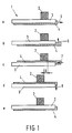
- Fig. 1 diagrammatically illustrates one of the possible techniques of displacing goods placed in a shop rack in a desired direction, i.e., towards the side adjoining the passageway for the public.
- conveyor belts extending transversely to the longitudinal direction of a shelf and capable of taking along the goods in the desired direction.
- the conveyor belts may be supported in addition to two end rollers by supporting rollers in the area intermediate the end rollers, and may for example be driven periodically.
- a system operating by the so-called moving-floor principle use can be made of a system operating by the so-called moving-floor principle.
- system articles placed on a supporting surface can be displaced by virtue of the fact that the supporting surface is constituted by a plurality of groups of elongate slats movable in the longitudinal direction.
- the slats are, for example, first moved one by one in one direction, sliding under the articles, because the latter are supported simultaneously on a plurality of slats which are not moved. Subsequently, the slats are all moved simultaneously in the other direction, so that the articles are taken along.
- the articles to be displaced are invariably moved in one plane.
- the articles to be displaced are lifted off the supporting surface, moved in the desired direction for a pre-determined distance, and are then again lowered on to the supporting surface.
- Fig. 1 is a diagrammatic side-elevational view, showing a shelf 1 of a shop rack, on which an article 2 has been placed.
- the shelf is comprised of two interengaging parts 3 and 4.
- the parts 3 and 4 can be moved relatively to each other in a manner to be described hereinafter and by means to be described hereinafter.
- Fig. 1 shows at a-e five positions which the shelf sections and an article to be displaced can occupy.
- the article 2 is supported by the first shelf section 3.
- This may be a carrier comprised of slats, such as strips, mounted in side-by-side, spaced parallel relationship.
- the second shelf section 4 may be built up in a similar way, with the slats disposed in the interspaces between the slats of shelf section 3.
- the first shelf section is stationary, and the second is at a slightly lower level than the first. This, however, is not essential.
- the second shelf section 4 is moved to the rear (i.e., to the right in Fig. 1), as indicated by an arrow 5.
- the second shelf section is preferably first moved downwardly somewhat. In certain conditions, specifically when there is lower friction between the second shelf section and the article 2 than there is between the stationary first shelf section and the article 2, it is in principle unnecessary for the second shelf section to be first moved downwards.
- the first intermediate position, reached from the initial position shown in Fig. 1a by shifting the second shelf section backwards is shown in Fig. 1b.
- the next step is an upward movement of the second shelf section, as indicated by an arrow 6.
- the second shelf section is moved forwardly, i.e., to the left in Fig. 1, as indicated by an arrow 7 in Fig. 1c. During this movement, the second shelf section takes along the article 2 over a pre-determined distance, so that the position shown in Fig. 1d is reached.
- Fig. 1e corresponds essentially to Fig. 1a, with the difference that the article 2 has been transported forwardly through a distance X.
- the article or the row of articles is in the desired position, with the rack being entirely filled at the front.
- a raised edge or the like is provided at the front to prevent the articles from falling out of the rack.
- Fig. 1 illustrates a variant of the technique shown in Fig. 1.
- the article 2 is supported in the rest position on the first shelf section 3.
- the second shelf section 4 is then subjacent to (or at the same level as) the first shelf section.
- the second shelf section is moved upwards (arrow 10) thereby taking over article 2.
- the first shelf section 3 is moved backwards (arrow 11).
- the second shelf section moves downwards again (arrow 12) until the article is again supported by the first shelf section, as shown in Fig. 2d.
- the first shelf section moves forward again, i.e., to the starting position, as indicated by an arrow 13, until the condition shown in Fig. 2e is reached.
- the second shelf section moves upward from a low position, thereby lifting the article off the first shelf section. Subsequently, the second shelf section moves forward and then downwards until the article is back on the first shelf section 3. Finally, the second shelf section moves back into the starting position (Fig. 3e).
- slats which extend transversely to the longitudinal direction of the shelf concerned and are movable relatively to each other, which slats are divided into at least two relatively movable groups.
- the slats may advantageously constitute lattices formed of strips, ribbons, rods, wires or threads, with the slats of one lattice being interposed between the slats of the other lattice, with both lattices being movable in the vertical direction, and one being movable in a horizontal direction relative to the other through a certain distance.
- the lattice slats should be arranged to pass each other in the vertical direction, which excludes the use of cross-connections, unless the slats are provided with notches or discontinuities.
- Figs.4 and 5 diagrammatically show an example of a conveyor system or use in a shop rack, which operates in the manner described above and thus permits cross-connections in the supported surface.
- the supporting surface of the shelf of a shop rack consists of a wire lattice 20 with longitudinal wires 21 and transverse wires or cross-wires 22.
- the longitudinal wires extend in the direction of transport, i.e., transversely relative to the longitudinal direction of the shelf, and the cross-wires extend transversely to the direction of transport.
- a carrier 23 provided with studs 24.
- the carrier is arranged just below the wire lattice in such a manner that the studs 24 can extend through the meshes of the wire lattice. Furthermore, the length of each mesh of the wire lattice, as viewed in the direction of the longitudinal wires 21, exceeds the corresponding dimension of studs 24.
- Fig. 2 shows, in steps a-d, the manner in which a row, not shown, of articles placed on the shelf can be moved to the left.
- Figs. 1-3 shows, in steps a-d, the manner in which a row, not shown, of articles placed on the shelf can be moved to the left.
- variants are possible, similar to those described with reference to Figs. 1-3.
- Fig. 5 shows in top plan view diagrammatically a portion of a shelf as illustrated in Fig. 4 in the situation shown in Fig. 4a or 4b.
- the lattice may intratley be made of horizontally and/or vertically disposed strips, in combination with wire or rod material, or otherwise.
- the studs may be formed integrally with a substantially imperforate carrier, as shown, but may alternatively be separate members mounted on a carrier, each forming one or more studs.
- the carrier of the studs may be formed as a wire lattice, a lattice of strips, or the like, to which studs made of a suitable material, e.g., plastics, are secured.
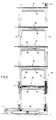
- Fig. 6 diagrammatically shows in side-elevational view an example of a shop rack according to the invention
- Fig. 7 shows, on a larger scale, the lower portion of Fig. 6.
- the rack shown comprises a frame with front uprights 31 and rear uprights 32.
- the rear uprights may constitute part of a closed rear wall. It is also possible to use a self-supporting closed rear wall. In the two latter cases, however, it is not possible to replenish the rack from the back.
- the shelves are all of the self-trimming type. If desired, the bottom plate 38 may be of the self-trimming type as well.
- the shelves shown are built up, in accordance with the principle shown in Figs. 4 and 5, of a lattice 39 and a carrier 41 provided with studs 40.
- the transporting movement similarly to the arrangement shown in Figs. 4 and 5, is fully carried out by the studded carrier, while the lattice 39, which in this example is a wire lattice built up from longitudinal wires 42 and cross-wires 43, is stationary.
- the wire lattice is formed so that the longitudinal wires 42 constitute the supporting surface for the products, while the cross-wires 43 are located under the longitudinal wires and support these.
- the cross-wires themselves, at least some of them, are carried by supporting blocks 45, which, in turn, are secured to frame members, not shown, fixedly connected to uprights 31,32.
- the wire lattice 39 extends at the front beyond the front upright 31, and is provided with a stop 44 to prevent the products from falling off the shelf.
- the stop is a cross-wire provided on the longitudinal wires, but other forms are possible. The required height of the stop depends on the shape of the products and on the size of the vertical stroke of the conveyor mechanism.
- the lattice of studs is built up from a plurality of studded strips, which extend in the longitudinal direction of the rack, i.e., across the direction of transport.
- a studded strip is shown in Fig. 7 at 46 in cross-sectional view, and in Fig. 8 in longitudinal sectional view.
- the studded strips have somewhat elongated studs, as viewed in the direction of movement, which as shown in Fig. 8 may be of angular castellated form, but alternatively may have a more rounded form.
- Fig. 9 shows, in perspective view, an example of a suitable studded strip.
- each elongated stud could be sub-divided into one or more smaller studs.
- the studded strips are moulded plastics strips, each carried by a metal section.
- a channel section 47 has been used.
- the channel sections 47 each rest on two or more carriers 41, extending between a front and a rear upright of the rack, which in the example shown consist of a vertical rectangular metal section.
- the channel sections 47 are coupled by means of draggers 47a to carriers 41, as shown in Fig. 8.
- Carriers 41 are vertically movable up and down in a manner to be described hereinafter, and are also reciprocatable in the longitudinal direction, as indicated by arrows 48 (Fig. 8) and 49 (Figs. 6 and 7).
- the movements of the moving parts of the shelves, required for trimming the articles placed on the shelves can be accomplished in various ways. It is possible for the moving parts of a shelf to be driven, starting from a rotary movement, generated in one of the manners known for the purpose, by means of eccentric transmission. It is also possible to effect a reciprocating movement directly by means of well-known hydraulic, pneumatic, electric or electromagnetic elements.
- the driving mechanism shown diagrammatically in Figs. 6 and 7 uses pneumatic tubes for causing the required movements of the movable part of the shelves, in this example the studded carriers.
- the rack is arranged so that all shelves of the rack are operated simultaneously.
- a pair of uprights 50,51 is arranged for up and down movement next to, or between, at least two pairs of fixed uprights 31,32.
- Uprights 50,51 are slidably coupled with the fixed uprights in a manner not shown.
- the movable uprights 50,51 each rest on a lift strip 52, located in a horizontal rectangular or U-shaped section 53, which in this example extends in the longitudinal direction of the rack.
- a pneumatic tube 54 coupled to a source of compressed air in a manner not shown.
- a vertical pushing strip 55 is provided in the rear movable uprights 51.
- the vertical pushing strip has a surface facing the front of the rack, which is in contact with the ends of carriers 41. If the carriers 41 are platforms or the like, rather than sections, suitable projections are provided.
- the rear ends of carriers 41 extend through openings in the wall of the movable uprights 51 into said uprights. Similarly, the front ends of carriers 41 extend into the front movable uprights 50.
- a pneumatic hose 56 Disposed behind the vertical pushing strip 55 is a pneumatic hose 56, arranged within the hollow movable uprights 51, which hose expands under pressure and then pushes the pushing strip forwardly.
- the carriers 41 are slidable in openings in the movable uprights 50,51.
- the vertical pneumatic hoses are energized. Subsequently, the horizontal hoses are released, as a result of which the movable uprights with the stud carriers move downwardly by gravity. Thereafter the vertical hoses are released.
- corresponding pneumatic hoses could be used in the front movable uprights 50.
- a resetting spring is used, which in this example is the compression spring 57 arranged between the end of the carriers 41 extending into the front uprights, and the inner wall of these uprights.
- Shown at 58 is a connecting hose for the vertical pushing hose 56.
- the connecting hose 58 in this example, extends through the fixed rear upright 32, and is coupled to pushing hose 56 at 59 at the top of the rack.
- the front and rear movable uprights are preferably interconnected with a connector 59 at least some shelves.
- the connectors are shown below the level of the shelves.
- the connectors are arranged just above the level of the shelves, as shown in Fig. 6 in ghost outline at 60.
- the connectors can then also serve as guides for the articles to be conveyed on the shelves and prevent the articles to be conveyed from catching behind an upright.
- the rear of the rack is preferably of open construction or one that can be opened in a simple manner.
- the racks should be accessible at the rear. This latter is often not the case, because the racks are often arranged against a wall or back-to-back with other racks.
- a shop rack according to the invention is preferably of mobile construction, as shown in Figs. 6 and 7. Wheels 61 and 62 travel over shop floor 63.
- a toothed rack 64,65 is provided on the shop floor and on the bottom of the rack, respectively.
- a pinion 66 Arranged between, and meshing with, the toothed racks is a pinion 66, which for example can be driven by means of a motor or manually through an operating rod.
- the toothed racks may be toothed plastics strips.
- a guide rod 67 for trolleys and the like is shown at the front of the rack.
- thin strips may be arranged between the top face of a series of studs and the bottom of the products, which strips are located between the longitudinal wires 42 of the wire lattice above the cross-wires. Such strips are then thinner than the longitudinal wires 42 and consequently carry the products only during a conveying stroke.
- the strips render it possible to use fewer and/or smaller studs, so that, for example, it is not necessary for a studded strip to be arranged under the foremost part of a shelf.
- Such strips may be arranged to lie loosely, but are preferably connected to the stud at a plurality of points, for example, by means of a nesting clamping connection. An example is shown diagrammatically in Fig. 10.
- Fig. 10 shows a studded platform 70 with studs 71. Arranged between the studs are, again, cross-wires 43 of a lattice 39. Furthermore, part of a longitudinal wire 42 of the lattice is visible. The direction of transport is indicated by an arrow 72. Some of the studs are provided with a projection 73, which fits within or around a projection 74, of complementary shape, provided at the bottom of a thin strip 75, for example of plastics, located on the transverse wires.
- a stretched piece of driving chain could be used instead of a toothed rack.
- the pinion could be secured to the bottom of the rack so as to be fixed, but rotatable. The top toothed rack can then be done without.
- a shop rack according to this invention can be equipped with means, such as light-sensitive elements and appurtenant light sources, by means of which it can be detected whether there are any products on the front part of a shelf. If not, the conveyor system can be energized (automatically) for the rack in question.
Landscapes
- Engineering & Computer Science (AREA)
- Mechanical Engineering (AREA)
- Warehouses Or Storage Devices (AREA)
- Vending Machines For Individual Products (AREA)
- Table Equipment (AREA)
- Handcart (AREA)
Claims (17)
- Ladenregal mit mehreren Fächern (33-37), in denen Artikel ausgestellt werden können, und einem die Fächer (33-37) hältenden Rahmen, bei dem eine Anzahl von Fächern mit Fördereinrichtungen (3,4), die zum Transportieren von in dem Fach plazierten Artikeln zur Vorderseite des Faches imstande sind, und mit Antriebseinrichtungen (54,55) für die Fördereinrichtungen (3,4) versehen ist,
dadurch gekennzeichnet,
daß die Antriebseinrichtungen derart angeordnet sind, daß sie gleichzeitig für mindestens einige übereinanderliegende Fächer (33-37) dient. - Ladenregal nach Anspruch 1, dadurch gekennzeichnet, daß die Antriebseinrichtungen mehrere pneumatische Schläuche (54) aufweisen, die expandieren, wenn ein Druckmedium unter Druck in sie gepumpt wird.
- Ladenregal nach Anspruch 2, dadurch gekennzeichnet, daß die Antriebseinrichtungen mehrere bewegbare Vertikalteile (50,51) aufweisen, die vertikal bewegbare Teile (41) mehrerer Fächer tragen, die derart angeordnet sind, daß sie mittels Kraftübertragungseinrichtungen durch Aktivierung eines oder mehrerer pneumatischer Schläuche (54) zusammen auf- und abbewagbar sind.
- Ladenregal nach Anspruch 3, dadurch gekennzeichnet, daß jedes der bewegbaren Vertikalteile (50,51) auf einer Hebeleiste (52) steht, wobei dei Hebeleisten (52) ihrerseits auf einem pneumatischen Schlauch (54) ruhen, der in einem Halteabschnitt angeordnet ist.
- Ladenregal nach Anspruch 3 oder 4, dadurch gekennzeichnet, daß die bewegbaren Vertikalteile (50,51) in der Nähe von feststehenden Vertikalteilen (31,32) angeordnet und derart an den feststehenden Vertikalteilen (31,32) befestigt sind, daß sie aufwärts und abwärts gleitbar sind.
- Ladenregal nach einem der Ansprüche 3 - 5, dadurch gekennzeichnet, daß die vertikal bewegbaren Teile (41) der Fächer zur Vor- und Zurückbewegung in vertikaler Richtung von dem bewegbaren Vertikalteilen getragen sind.
- Ladenregal nach Anspruch 6, dadurch gekennzeichnet, daß mindestens einige zumindest der bewegbaren Vertikalteile (50,51) an einer Längsseite des Regals hohle Vertikalteile sind, in denen ein pneumatischer Schlauch (56) untergebracht ist, der durch Kraftübertragungseinrichtungen in arbeitsmäßiger Verbindung mit den bewegbaren Teilen (41) der Fächer steht.
- Ladenregal nach Anspruch 7, dadurch gekennzeichnet, daß der pneumatische Schlauch (56) innerhalb der hohlen Vertikalteile (51) zwischen einem Wandteil der hohlen Vertikalteile (51) und einer Schiebeleiste (55), die in den hohlen Vertikalteilen angeordnet ist, hängt, und daß auf der Ebene der Fächer in dem Wandbereich der hohlen Vertikalteile (51) der Schiebeleiste (55) gegenüberliegend Öffnungen vorgesehen sind, durch die sich Vorsprünge der bewegbaren Teile (41) der Fächer in die hohlen Vertikalteile (51) erstrecken.
- Ladenregal nach einem der Ansprüche 6 - 8, gekennzeichnet durch Rückstelleinrichtungen (57), die in horizontaler Richtung mit den bewegbaren Teilen der Fächer zusammenwirken.
- Ladenregal nach Anspruch 7 oder 8 und Anspruch 9, dadurch gekennzeichnet, daß ein Vertikalteil eines Paares bewegbarer Vertikalteile, die einander an unterschiedlichen Längeseiten eines Regals gegenüberliegen, ein pneumatischer Schlauch ist, und daß das andere Vertikalteil des Paares Rückstellfedern (57) enthält, die mit den bewegbaren Teilen (41) der Fächer zusammenwirken.
- Ladenregal nach einem der Ansprüche 3 - 10, dadurch gekennzeichnet, daß jedes Paar bewegbarer Vertikalteile (50,51), die einander an unterschiedlichen Längsseiten eines Regals gegenüberliegen, durch Konnektoren (59) starr miteinander verbunden ist.
- Ladenregal nach Anspruch 11, dadurch gekennzeichnet, daß die Konnektoren (59) mehrere Leisten aufweisen, die geringfügig über der Ebene der Fächer angeordnet sind und ferner als Führung für in den Fächern plazierte Artikel dienen.
- Ladenregal nach einen der vorhergehenden Ansprüche, dadurch gekennzeichnet, daß das Regal eine Rückwand aufweist, die ein Wiederauffüllen der Fächer (33-37) von hinten erlaubt.
- Ladenregal nach Anspruch 13, dadurch gekennzeichnet, daß das Regal mindestens quer zur Längsrichtung der Fächer (33-37) bewegbar ist.
- Ladenregal nach Anspruch 13, gekennzeichnet durch mindestens ein am Boden des Regals montiertes antreibbares Zahnrad (66), das mit mindestens einer Zahnstange (64,65) in Eingriff ist.
- Ladenregal nach einem der vorhergehenden Ansprüche, gekennzeichnet durch Detektionseinrichtungen, die mit mindestens einem Abschnitt der Front eines oder mehrerer Fächer (33-37) zusammenwirken, um festzustellen, ob der Abschnitt an der Frontseite Artikel trägt, und die bei Nichtvorhandensein von Artikeln an der Frontseite der Abschnitte die Aktivierung der Fördereinrichtungen veranlassen können.
- Ladenregal nach Anspruch 16, dadurch gekennzeichnet, daß die Detektionseinrichtungen mindestens eine lichtempfindliche Zelle und eine zugehörige Lichtquelle aufweisen.
Applications Claiming Priority (3)
| Application Number | Priority Date | Filing Date | Title |
|---|---|---|---|
| NL8702725 | 1987-11-13 | ||
| NL8702725A NL8702725A (nl) | 1987-11-13 | 1987-11-13 | Automatisch transportsysteem met meervoudige draagvlakken. |
| EP19880202534 EP0320031B1 (de) | 1987-11-13 | 1988-11-14 | Ladenregal |
Related Parent Applications (1)
| Application Number | Title | Priority Date | Filing Date |
|---|---|---|---|
| EP88202534.9 Division | 1988-11-14 |
Publications (3)
| Publication Number | Publication Date |
|---|---|
| EP0481969A2 EP0481969A2 (de) | 1992-04-22 |
| EP0481969A3 EP0481969A3 (en) | 1992-09-02 |
| EP0481969B1 true EP0481969B1 (de) | 1994-09-28 |
Family
ID=19850917
Family Applications (2)
| Application Number | Title | Priority Date | Filing Date |
|---|---|---|---|
| EP19880202534 Expired - Lifetime EP0320031B1 (de) | 1987-11-13 | 1988-11-14 | Ladenregal |
| EP92200169A Expired - Lifetime EP0481969B1 (de) | 1987-11-13 | 1988-11-14 | Ladenregal |
Family Applications Before (1)
| Application Number | Title | Priority Date | Filing Date |
|---|---|---|---|
| EP19880202534 Expired - Lifetime EP0320031B1 (de) | 1987-11-13 | 1988-11-14 | Ladenregal |
Country Status (4)
| Country | Link |
|---|---|
| EP (2) | EP0320031B1 (de) |
| DE (2) | DE3851710T2 (de) |
| ES (2) | ES2065122T3 (de) |
| NL (1) | NL8702725A (de) |
Families Citing this family (7)
| Publication number | Priority date | Publication date | Assignee | Title |
|---|---|---|---|---|
| IT1270394B (it) * | 1992-12-14 | 1997-05-05 | Piero Antinori | Ripiano per scaffalature di mercati self-service dotato di un tappeto trasportatore in grado di condurre la merce sistemata verso il fondo progressivamente verso il fronte |
| FR2716782B1 (fr) * | 1994-03-03 | 1996-06-28 | Maurice Ayed | Etagère mobile. |
| AU2217795A (en) * | 1995-03-29 | 1996-10-16 | Maurice Ayed | Movable shelving |
| SE511953C2 (sv) * | 1998-02-16 | 1999-12-20 | Sebastian Brodin | Hyllanordning med frammatningsanordning |
| SE526549C2 (sv) * | 2003-11-06 | 2005-10-04 | Easy Link Ab | Hyllanordning |
| DE102005058478A1 (de) | 2005-12-07 | 2007-06-14 | Walter Winkler | Einzelhandelversorgungssystem |
| DE102020129296A1 (de) * | 2020-11-06 | 2022-05-12 | Dyemansion Gmbh | Trägergestell für Bauteile in einer Prozesskammer |
Family Cites Families (6)
| Publication number | Priority date | Publication date | Assignee | Title |
|---|---|---|---|---|
| FR1288955A (fr) * | 1960-03-07 | 1962-03-30 | Dispositif pour le déplacement manuel de compartiments d'emmagasinement, réceptacles ou analogues | |
| US3048258A (en) * | 1961-05-31 | 1962-08-07 | John F Skold | Multiple conveyor |
| FR1346487A (fr) * | 1962-11-09 | 1963-12-20 | Baele Gangloff Ste Nouvelle | Dispositif de transport d'objets divers notamment de récipients |
| FR2092826B1 (de) * | 1970-06-23 | 1975-01-10 | Delcambre Gerard | |
| US3881633A (en) * | 1973-04-02 | 1975-05-06 | Si Handling Systems | Apparatus for dispensing items from shelves |
| GB2185457A (en) * | 1986-01-16 | 1987-07-22 | Marryat Handling Systems Limit | Material handling apparatus |
-
1987
- 1987-11-13 NL NL8702725A patent/NL8702725A/nl not_active Application Discontinuation
-
1988
- 1988-11-14 DE DE19883851710 patent/DE3851710T2/de not_active Expired - Fee Related
- 1988-11-14 ES ES92200169T patent/ES2065122T3/es not_active Expired - Lifetime
- 1988-11-14 ES ES88202534T patent/ES2037205T3/es not_active Expired - Lifetime
- 1988-11-14 EP EP19880202534 patent/EP0320031B1/de not_active Expired - Lifetime
- 1988-11-14 EP EP92200169A patent/EP0481969B1/de not_active Expired - Lifetime
- 1988-11-14 DE DE19883878191 patent/DE3878191T2/de not_active Expired - Fee Related
Also Published As
| Publication number | Publication date |
|---|---|
| DE3851710D1 (de) | 1994-11-03 |
| NL8702725A (nl) | 1989-06-01 |
| EP0481969A3 (en) | 1992-09-02 |
| DE3851710T2 (de) | 1995-04-06 |
| ES2037205T3 (es) | 1993-06-16 |
| EP0320031A1 (de) | 1989-06-14 |
| ES2065122T3 (es) | 1995-02-01 |
| DE3878191T2 (de) | 1993-07-15 |
| EP0320031B1 (de) | 1993-02-03 |
| DE3878191D1 (de) | 1993-03-18 |
| EP0481969A2 (de) | 1992-04-22 |
Similar Documents
| Publication | Publication Date | Title |
|---|---|---|
| US9975697B2 (en) | Storage and order collection system | |
| US7686560B2 (en) | Rack, conveyor and shuttle automated pick system | |
| EP0139650B1 (de) | Verfahren und vorrichtung zum laden eines lager- oder transportregals | |
| NL1038148C2 (nl) | Opslag- en orderverzamelsysteem. | |
| JPH09506064A (ja) | 高速度収納装置 | |
| JPS61178817A (ja) | パックを集積および包装ステーションに送るための方法および装置 | |
| EP0481969B1 (de) | Ladenregal | |
| US3978970A (en) | Loader for containerized cooker | |
| US20080019818A1 (en) | Stacking apparatus for comestible portions on carrier sheets and method for stacking | |
| EP1608573B1 (de) | Vorrichtung zur lagerung und zuführung von produkten | |
| US3837511A (en) | Method of loading and unloading articles in a storage apparatus | |
| US5615994A (en) | Article conveying, grouping and storing apparatus | |
| CN114524245A (zh) | 一种具有理料功能的物料输送装置 | |
| US3591041A (en) | Denesting machine | |
| CA2532116C (en) | Rack, conveyor and shuttle automated pick system | |
| US3731824A (en) | Food storage and handling system apparatus | |
| US5108005A (en) | Method and apparatus for automatically dispensing items from shelves | |
| US2890556A (en) | Article transfer mechanism | |
| CN209701034U (zh) | 一种新型面包包装设备 | |
| CN213622055U (zh) | 理料输送装置 | |
| CN119657517B (zh) | 一种智能播种墙分拣装置 | |
| BE1025801B1 (nl) | Verticaal opslagsysteem | |
| JP2684503B2 (ja) | 物品の荷受方法及び装置 | |
| JP2878541B2 (ja) | 集荷方法及び装置 | |
| SU903248A1 (ru) | Устройство дл укладки изделий в контейнер с полками |
Legal Events
| Date | Code | Title | Description |
|---|---|---|---|
| PUAI | Public reference made under article 153(3) epc to a published international application that has entered the european phase |
Free format text: ORIGINAL CODE: 0009012 |
|
| 17P | Request for examination filed |
Effective date: 19920121 |
|
| AC | Divisional application: reference to earlier application |
Ref document number: 320031 Country of ref document: EP |
|
| AK | Designated contracting states |
Kind code of ref document: A2 Designated state(s): BE DE ES FR GB IT NL SE |
|
| PUAL | Search report despatched |
Free format text: ORIGINAL CODE: 0009013 |
|
| AK | Designated contracting states |
Kind code of ref document: A3 Designated state(s): BE DE ES FR GB IT NL SE |
|
| 17Q | First examination report despatched |
Effective date: 19931116 |
|
| GRAA | (expected) grant |
Free format text: ORIGINAL CODE: 0009210 |
|
| AC | Divisional application: reference to earlier application |
Ref document number: 320031 Country of ref document: EP |
|
| AK | Designated contracting states |
Kind code of ref document: B1 Designated state(s): BE DE ES FR GB IT NL SE |
|
| PG25 | Lapsed in a contracting state [announced via postgrant information from national office to epo] |
Ref country code: BE Effective date: 19940928 |
|
| PGFP | Annual fee paid to national office [announced via postgrant information from national office to epo] |
Ref country code: GB Payment date: 19940930 Year of fee payment: 7 |
|
| PGFP | Annual fee paid to national office [announced via postgrant information from national office to epo] |
Ref country code: SE Payment date: 19941014 Year of fee payment: 7 |
|
| REF | Corresponds to: |
Ref document number: 3851710 Country of ref document: DE Date of ref document: 19941103 |
|
| PGFP | Annual fee paid to national office [announced via postgrant information from national office to epo] |
Ref country code: FR Payment date: 19941122 Year of fee payment: 7 |
|
| PGFP | Annual fee paid to national office [announced via postgrant information from national office to epo] |
Ref country code: ES Payment date: 19941124 Year of fee payment: 7 |
|
| PGFP | Annual fee paid to national office [announced via postgrant information from national office to epo] |
Ref country code: NL Payment date: 19941130 Year of fee payment: 7 Ref country code: BE Payment date: 19941130 Year of fee payment: 7 |
|
| ET | Fr: translation filed | ||
| PGFP | Annual fee paid to national office [announced via postgrant information from national office to epo] |
Ref country code: DE Payment date: 19941219 Year of fee payment: 7 |
|
| ITF | It: translation for a ep patent filed | ||
| EAL | Se: european patent in force in sweden |
Ref document number: 92200169.8 |
|
| REG | Reference to a national code |
Ref country code: ES Ref legal event code: FG2A Ref document number: 2065122 Country of ref document: ES Kind code of ref document: T3 |
|
| PLBE | No opposition filed within time limit |
Free format text: ORIGINAL CODE: 0009261 |
|
| STAA | Information on the status of an ep patent application or granted ep patent |
Free format text: STATUS: NO OPPOSITION FILED WITHIN TIME LIMIT |
|
| 26N | No opposition filed | ||
| PG25 | Lapsed in a contracting state [announced via postgrant information from national office to epo] |
Ref country code: GB Effective date: 19951114 |
|
| PG25 | Lapsed in a contracting state [announced via postgrant information from national office to epo] |
Ref country code: SE Effective date: 19951115 Ref country code: ES Free format text: LAPSE BECAUSE OF NON-PAYMENT OF DUE FEES Effective date: 19951115 |
|
| PG25 | Lapsed in a contracting state [announced via postgrant information from national office to epo] |
Ref country code: NL Effective date: 19960601 |
|
| GBPC | Gb: european patent ceased through non-payment of renewal fee |
Effective date: 19951114 |
|
| PG25 | Lapsed in a contracting state [announced via postgrant information from national office to epo] |
Ref country code: FR Effective date: 19960731 |
|
| NLV4 | Nl: lapsed or anulled due to non-payment of the annual fee |
Effective date: 19960601 |
|
| PG25 | Lapsed in a contracting state [announced via postgrant information from national office to epo] |
Ref country code: DE Effective date: 19960801 |
|
| EUG | Se: european patent has lapsed |
Ref document number: 92200169.8 |
|
| REG | Reference to a national code |
Ref country code: FR Ref legal event code: ST |
|
| REG | Reference to a national code |
Ref country code: ES Ref legal event code: FD2A Effective date: 20010503 |
|
| PG25 | Lapsed in a contracting state [announced via postgrant information from national office to epo] |
Ref country code: IT Free format text: LAPSE BECAUSE OF NON-PAYMENT OF DUE FEES;WARNING: LAPSES OF ITALIAN PATENTS WITH EFFECTIVE DATE BEFORE 2007 MAY HAVE OCCURRED AT ANY TIME BEFORE 2007. THE CORRECT EFFECTIVE DATE MAY BE DIFFERENT FROM THE ONE RECORDED. Effective date: 20051114 |