EP0482029B1 - Schlauchklemme - Google Patents
Schlauchklemme Download PDFInfo
- Publication number
- EP0482029B1 EP0482029B1 EP90910112A EP90910112A EP0482029B1 EP 0482029 B1 EP0482029 B1 EP 0482029B1 EP 90910112 A EP90910112 A EP 90910112A EP 90910112 A EP90910112 A EP 90910112A EP 0482029 B1 EP0482029 B1 EP 0482029B1
- Authority
- EP
- European Patent Office
- Prior art keywords
- tube
- arms
- hose
- flexible tube
- piston
- Prior art date
- Legal status (The legal status is an assumption and is not a legal conclusion. Google has not performed a legal analysis and makes no representation as to the accuracy of the status listed.)
- Expired - Lifetime
Links
- 230000007704 transition Effects 0.000 claims description 12
- 229920003023 plastic Polymers 0.000 claims description 4
- 239000004033 plastic Substances 0.000 claims description 4
- 239000000463 material Substances 0.000 claims description 3
- 238000006073 displacement reaction Methods 0.000 claims 1
- 230000006835 compression Effects 0.000 abstract 1
- 238000007906 compression Methods 0.000 abstract 1
- 208000027418 Wounds and injury Diseases 0.000 description 15
- 230000000694 effects Effects 0.000 description 5
- 206010048629 Wound secretion Diseases 0.000 description 2
- 238000005516 engineering process Methods 0.000 description 2
- 230000001681 protective effect Effects 0.000 description 2
- 230000033228 biological regulation Effects 0.000 description 1
- 230000015572 biosynthetic process Effects 0.000 description 1
- 238000010276 construction Methods 0.000 description 1
- 230000007423 decrease Effects 0.000 description 1
- 230000001419 dependent effect Effects 0.000 description 1
- 238000011161 development Methods 0.000 description 1
- 230000018109 developmental process Effects 0.000 description 1
- 239000012530 fluid Substances 0.000 description 1
- 230000001105 regulatory effect Effects 0.000 description 1
- 230000000284 resting effect Effects 0.000 description 1
- 230000028327 secretion Effects 0.000 description 1
Images

Classifications
-
- A—HUMAN NECESSITIES
- A61—MEDICAL OR VETERINARY SCIENCE; HYGIENE
- A61M—DEVICES FOR INTRODUCING MEDIA INTO, OR ONTO, THE BODY; DEVICES FOR TRANSDUCING BODY MEDIA OR FOR TAKING MEDIA FROM THE BODY; DEVICES FOR PRODUCING OR ENDING SLEEP OR STUPOR
- A61M39/00—Tubes, tube connectors, tube couplings, valves, access sites or the like, specially adapted for medical use
- A61M39/22—Valves or arrangement of valves
- A61M39/28—Clamping means for squeezing flexible tubes, e.g. roller clamps
-
- A—HUMAN NECESSITIES
- A61—MEDICAL OR VETERINARY SCIENCE; HYGIENE
- A61M—DEVICES FOR INTRODUCING MEDIA INTO, OR ONTO, THE BODY; DEVICES FOR TRANSDUCING BODY MEDIA OR FOR TAKING MEDIA FROM THE BODY; DEVICES FOR PRODUCING OR ENDING SLEEP OR STUPOR
- A61M1/00—Suction or pumping devices for medical purposes; Devices for carrying-off, for treatment of, or for carrying-over, body-liquids; Drainage systems
- A61M1/71—Suction drainage systems
- A61M1/73—Suction drainage systems comprising sensors or indicators for physical values
- A61M1/732—Visual indicating means for vacuum pressure
-
- A—HUMAN NECESSITIES
- A61—MEDICAL OR VETERINARY SCIENCE; HYGIENE
- A61M—DEVICES FOR INTRODUCING MEDIA INTO, OR ONTO, THE BODY; DEVICES FOR TRANSDUCING BODY MEDIA OR FOR TAKING MEDIA FROM THE BODY; DEVICES FOR PRODUCING OR ENDING SLEEP OR STUPOR
- A61M1/00—Suction or pumping devices for medical purposes; Devices for carrying-off, for treatment of, or for carrying-over, body-liquids; Drainage systems
- A61M1/71—Suction drainage systems
- A61M1/74—Suction control
-
- A—HUMAN NECESSITIES
- A61—MEDICAL OR VETERINARY SCIENCE; HYGIENE
- A61M—DEVICES FOR INTRODUCING MEDIA INTO, OR ONTO, THE BODY; DEVICES FOR TRANSDUCING BODY MEDIA OR FOR TAKING MEDIA FROM THE BODY; DEVICES FOR PRODUCING OR ENDING SLEEP OR STUPOR
- A61M1/00—Suction or pumping devices for medical purposes; Devices for carrying-off, for treatment of, or for carrying-over, body-liquids; Drainage systems
- A61M1/71—Suction drainage systems
- A61M1/74—Suction control
- A61M1/743—Suction control by changing the cross-section of the line, e.g. flow regulating valves
-
- A—HUMAN NECESSITIES
- A61—MEDICAL OR VETERINARY SCIENCE; HYGIENE
- A61M—DEVICES FOR INTRODUCING MEDIA INTO, OR ONTO, THE BODY; DEVICES FOR TRANSDUCING BODY MEDIA OR FOR TAKING MEDIA FROM THE BODY; DEVICES FOR PRODUCING OR ENDING SLEEP OR STUPOR
- A61M1/00—Suction or pumping devices for medical purposes; Devices for carrying-off, for treatment of, or for carrying-over, body-liquids; Drainage systems
- A61M1/64—Containers with integrated suction means
- A61M1/66—Pre-evacuated rigid containers, e.g. Redon bottles
-
- Y—GENERAL TAGGING OF NEW TECHNOLOGICAL DEVELOPMENTS; GENERAL TAGGING OF CROSS-SECTIONAL TECHNOLOGIES SPANNING OVER SEVERAL SECTIONS OF THE IPC; TECHNICAL SUBJECTS COVERED BY FORMER USPC CROSS-REFERENCE ART COLLECTIONS [XRACs] AND DIGESTS
- Y10—TECHNICAL SUBJECTS COVERED BY FORMER USPC
- Y10S—TECHNICAL SUBJECTS COVERED BY FORMER USPC CROSS-REFERENCE ART COLLECTIONS [XRACs] AND DIGESTS
- Y10S137/00—Fluid handling
- Y10S137/907—Vacuum-actuated valves
Definitions
- the invention relates to a clamp for a hose, in the interior of which there is a different pressure than in its surroundings.
- hose clamps are therefore suitable for both negative and positive pressure systems.
- a preferred area of use for such a hose clamp is medical technology, where such a clamp can be used as a connection device for a vacuum suction bottle for suctioning off wound fluids during wound drainage.
- a suction bottle of this type is connected via a tube to a perforated wound drainage tube, which in turn is introduced into an airtightly closed wound cavity.
- the negative pressure prevailing in the feeding bottle thus also acts in the wound cavity, so that the wound secretion that forms there can be sucked into the bottle.
- sliding clamps are known for closing a hose, such as the hose between the vacuum suction bottle and the wound drainage hose (DE-A-37 24 483).
- These sliding clamps have two fork-like tines that are attached to each other in a V-shape. By moving these tines along their longitudinal extension relative to the hose, the hose cross-section can be squeezed together, thereby closing the hose.
- Such slide clamps allow regulation, i.e. H. a partial blockage of the hose cross section practically not.
- a generic hose clamp with which a hose cross section can be more or less blocked in a regulating manner, is known from DE-B-23 56 480.
- the valve of a container disclosed there has a lever in its lid area which rests on a rubber balloon as well as on a hose. This lever is also mounted twice so that it can be pivoted both clockwise and counterclockwise.
- the inside of the rubber balloon is connected to a tube that projects into the inside of the container.
- the hose, on which the lever also rests, represents an additional connection between the interior of the container and the surroundings of the container.
- the lever pivots clockwise, ie in the opposite direction. In both swivel directions, the lever has a relieving effect on the hose, so that the hose cross section is enlarged in both cases.
- the pressure inside the container will set in the rubber balloon. If the internal pressure of the container falls below a predetermined value, the rubber balloon will contract and release the tube cross-section. As a result, the pressure inside the container increases again to the preset value. If, on the other hand, the internal pressure of the container exceeds the specified value, the rubber balloon expands and the tube cross-section will also open.
- This hose clamp thus serves to regulate the internal pressure of the container to a certain value, which depends on the external pressure. If the pressure falls below a certain internal pressure in the container, this lower pressure which is established is immediately raised again by opening the hose cross section.
- the hose cross-section does not act as a throttling point. So it can not be achieved that outside the more or less squeezed together tube cross-section a constant negative pressure can be maintained, which is largely independent of the negative pressure prevailing in the container.
- the invention has for its object to provide a hose clamp of the type mentioned, which is a simple way to reduce a hose cross-section, so as to form a throttle point at this point in the hose cross-section.
- the hose clamp according to the invention for a hose connectable to a container, in the interior of which a different pressure is present relative to its surroundings, according to the preamble of claim 1 is accordingly characterized in that the connection between the interior of the secondary chamber and the hose is only an outside the secondary line or opening is present, the secondary line or opening is connected to the clamping point on the side of the hose facing away from the container to be connected, the arms are arranged on the wall of the secondary chamber in such a way that the arms can be moved relative to one another by changing the volume of the secondary chamber and as a result, the hose can be squeezed to different extents, the two arms moving toward one another when the vacuum increases in the hose and the two arms move away from one another only when the vacuum decreases in the hose.
- Such a hose clamp installed in a hose connection between, for example, a vacuum suction bottle and a wound drainage hose can thereby act independently as a throttle valve, since the pressure prevailing in the hose also acts in the interior of the secondary chamber via the secondary line and thus causes this interior to be relative to the prevailing external pressure adjusted accordingly.
- this negative pressure also acts in the secondary chamber, as a result of which the latter contract and, as a result, the arm connected to it can move relatively towards the other arm. The latter in turn has the consequence that the arms will compress the hose cross-section by a certain amount.
- the hose clamp will compress the hose until a balance has been established between the negative pressure acting through the hose cross-section and the negative pressure in the secondary chamber.
- a vacuum bottle with maximum negative pressure can be used without this maximum negative pressure then also being present in a wound area, for example.
- the secondary chamber is formed by a bellows-like body, this body being arranged between the two arms. It makes sense to pivotally attach the two arms, between which the body is present, to a sleeve piece; the sleeve piece can be designed so that it can be pulled over the hose in question, which is to be disconnected. Furthermore, the bellows-like body with its two end regions attached to both arms. The throttling effect of such a hose clamp depends on the materials and the constructive mutual arrangement of the individual components used.
- an elastic body can also be attached between the two arms, which acts as an attenuator.
- the throttling effect can be increased or weakened;
- this effect can also be achieved in that the bellows-like body can be fastened along the arms at different locations thereof.
- the bellows-like body it is also possible to provide a piston-cylinder arrangement, so that in this case the interior of the secondary chamber is formed by the interior delimited by the cylinder, piston and the hose wall. At least one of the arms is attached to the piston so that when the piston is adjusted in the cylinder, this arm is moved transversely to the longitudinal axis of the hose. In this case, the other arm resting against the hose can be stationary.
- the second arm can also be formed by another construction surrounding the hose, such as a wall piece.
- the piston will practically be movable towards the hose against the force of an elastically deformable body.
- This elastically deformable body can be an elastically flexible spring;
- the hose it is also possible to design the hose to be resilient, at least in the region that can be squeezed by the arms. If the hose is squeezed completely and thus its hose wall is deformed to the maximum in this squeezing area, the restoring force present in the hose wall will be directed against the pressing piston force, so that the pressure is reduced in the secondary chamber the restoring force of the hose will move the piston away from the hose wall and thus move it back.
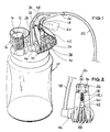
- a plastic bellows 12 is arranged, which is transparent approximately cylindrical protective cup 14 is surrounded (Fig. 1, 2). Bellows 12 and protective cup 14 act as pressure indicators 16 for the negative pressure prevailing inside the suction bottle 10.
- a maximally expanded bellows 12 indicates a minimum and an extremely widely contracted bellows 12 a maximum negative pressure of the feeding bottle 10.
- a hose 18 is connected to a second opening of the feeding bottle 10. This hose 18 is connected via a hose fork piece 20 to a hose 22 which can be connected to a drainage hose, not shown.
- a nozzle 24 is slipped over the hose 18. This nozzle 24 has at its end facing away from the feeding bottle 10 a collar piece 26. On this collar piece 26 two arms 28, 30 are pivotally attached with their ends by means of a joint 32, 34 each.
- the other ends of the two arms 28, 30 are fixedly attached to a bellows 38; When this bellows 38 is pulled together, the mutually facing inner sides 40, 42 of the two arms 28, 30 will move towards one another and compress the cross section of the hose 18 between them to a greater or lesser extent.
- a hose 48 is connected at one end to a connecting piece 46.
- the other end of this hose 48 is connected to the still free socket of the hose fork piece 20.
- the hose 18 and the hose 22 are fastened to the other two connecting pieces of this fork piece 20.
- the hose clamp 50 seated on the hose 18 acts in the following way:
- This reduced negative pressure thus also acts in the hose 22 and thus also in the wound drainage hose connected, for example.
- a reduced vacuum only acts in a human wound, for example, from which wound secretion is to be sucked into the vacuum suction bottle 10.
- a sliding clamp 60 In order to maintain the maximum negative pressure in the vacuum suction bottle 10 before it is used, a sliding clamp 60, shown in broken lines, is pushed onto the tube piece 18 in such a way that the tube 18 is completely closed at this point.
- the bellows 38 is thus connected to the atmosphere prevailing outside the bellows 38, so that it is present to a very large extent.
- the bellows 38 which is made of plastic to save costs, is thus in a relaxed state. This does not affect its elastic deformability, which in the other case, where it would be present for a longer period of time, would not be guaranteed by fatigue of the plastic material from which it is made.
- the sliding clamp 60 As soon as the feeding bottle 10 is properly connected to, for example, a human wound, the sliding clamp 60 is removed from the hose 18. As a result, the bellows 38 will suddenly contract and squeeze the hose 18 by a predetermined amount, as shown, for example, in FIG. 2 is.
- the hose clamp 62 according to the invention shown in FIG. 3 has a housing 64 with a lower connecting piece 66 and an upper connecting piece 68.
- the lower connecting piece 66 sits gas-tight on the neck 70 of the vacuum bottle 10.
- a transition hose piece 72 is also present in a gas-tight manner between the connector 66 and the neck 70. This piece of hose 72 runs through the interior 74 of the housing 64 and pushes out of the housing 64 in the region of the upper connector 68.
- a hose 18.2 is connected in a gas-tight manner in the area of the upper connector 68. The interior of the hose 18.2 is connected to the interior of the vacuum bottle 10.
- the housing 64 has a left flange piece 76 and an opposite right flange piece 78 on both sides of the transition tube piece 72.
- a wall 80 connects to the left flange piece 76.
- This wall has a central, collar-like projection in the form of a left arm 82. Only in the area of this left arm 82 is the wall 80 and thus the housing 64 in this area - i. H. in the drawing from the left - on the transition tube piece 72.
- the flange 78 On the side of the housing 64 opposite the wall 80, the flange 78 there is covered by a hat-like cap 84. An opening 86 is present in this cap 84 so that the atmospheric pressure existing outside the cap 84 also acts inside the cap 84.
- a piston 88 is longitudinally displaceable.
- the piston 88 is gas-tight on the inside of the flange 78.
- this piston 88 is made of rubber.
- This piston 88 has a collar-like projection in the form of a right arm 90, which is present with respect to the transition tube piece 72 exactly opposite the left arm 82. If the piston 88 is moved all the way to the left, the transition tube piece 72 becomes extreme in the area between the left arm 82 and the right arm 90 squeezed wide. This state is shown in Fig. 5.
- An opening 92 is provided in the wall of the transition tube piece 72 in the area of the housing 64.
- the pressure in the interior of the transition tube piece 72 can thus equalize with the pressure that is present in the housing 64 between the wall 80 and the piston 88.
- the cap 84 and the flange 78 have a mutual, for example bayonet-like locking device 94, so that the cap 84 can be fixed in its position shown in FIG. 5.
- the cap 64 presses the piston 88 extremely far to the left with molded-on wall parts 96, so that the transition tube piece 72 is completely squeezed together.
- the pressure prevailing in the vacuum bottle thus remains in the vacuum bottle.
- the position of the hose clamp 62 shown in FIG. 5 is present before the suction bottle 10 is used. In this position, the vacuum bottle 10 is brought to a patient with the hose clamp 62 attached to it.
- the cap 84 is unlocked, i. that is, the bayonet-type locking device 94 is unlocked.
- the cap 84 will then assume approximately its position shown in FIG. 3, which means that the passage through the transition tube piece 72 is more or less open.
- the negative pressure prevailing in the vacuum bottle 10 will then continue through the tube 18.2 into the wound area of the patient.
- a throttle point is thus also formed in the area between the arms 82, 90.
- This throttling point is influenced by the position of the piston 88. From the direction of the cap 84, the outside atmospheric pressure, for example atmospheric pressure, acts on this piston 88. which can also be set in terms of pressure in the interior 74 of the cap 84 through the opening 96. On the other side of the piston 88, the suction pressure which is present due to the negative pressure in the vacuum bottle and which is regularly lower than the atmospheric external pressure acts. This pressure can occur on the left side of the piston 88 in the drawing - in the interior 74 - due to the presence of the opening 92.
- the piston 88 is displaced to the right by the elastic configuration of the transition hose piece 72, ie by its restoring force.
- the pressure in the vacuum bottle and the elastic restoring force of the transition hose piece 72 a more or less pronounced throttling point will thus occur within the housing 64 between the arms 82 and 90.
- the hose clamp 62 thus represents a very simple possibility for the self-regulating formation of a throttle point in a hose.
Landscapes
- Health & Medical Sciences (AREA)
- Heart & Thoracic Surgery (AREA)
- Animal Behavior & Ethology (AREA)
- Veterinary Medicine (AREA)
- Anesthesiology (AREA)
- Biomedical Technology (AREA)
- Hematology (AREA)
- Life Sciences & Earth Sciences (AREA)
- Engineering & Computer Science (AREA)
- General Health & Medical Sciences (AREA)
- Public Health (AREA)
- Vascular Medicine (AREA)
- Pulmonology (AREA)
- Rigid Pipes And Flexible Pipes (AREA)
- Supports For Pipes And Cables (AREA)
- Media Introduction/Drainage Providing Device (AREA)
- Forklifts And Lifting Vehicles (AREA)
- External Artificial Organs (AREA)
- Seal Device For Vehicle (AREA)
Applications Claiming Priority (2)
| Application Number | Priority Date | Filing Date | Title |
|---|---|---|---|
| DE8908336U DE8908336U1 (de) | 1989-07-08 | 1989-07-08 | Schlauchklemme |
| DE8908336U | 1989-07-08 |
Publications (2)
| Publication Number | Publication Date |
|---|---|
| EP0482029A1 EP0482029A1 (de) | 1992-04-29 |
| EP0482029B1 true EP0482029B1 (de) | 1993-10-13 |
Family
ID=6840903
Family Applications (1)
| Application Number | Title | Priority Date | Filing Date |
|---|---|---|---|
| EP90910112A Expired - Lifetime EP0482029B1 (de) | 1989-07-08 | 1990-07-07 | Schlauchklemme |
Country Status (8)
| Country | Link |
|---|---|
| US (1) | US5238217A (da) |
| EP (1) | EP0482029B1 (da) |
| JP (1) | JP2930410B2 (da) |
| AT (1) | ATE95898T1 (da) |
| DE (2) | DE8908336U1 (da) |
| DK (1) | DK0482029T3 (da) |
| ES (1) | ES2047938T3 (da) |
| WO (1) | WO1991000970A1 (da) |
Families Citing this family (27)
| Publication number | Priority date | Publication date | Assignee | Title |
|---|---|---|---|---|
| DE4107044A1 (de) * | 1991-03-06 | 1992-09-10 | Joka Kathetertechnik Gmbh | Absperrvorrichtung an einer fluessigkeitsleitung, insbesondere einer fluessigkeitsentnahme- oder infusionseinrichtung |
| DE4414613C2 (de) * | 1994-04-27 | 1997-01-23 | Sterimed Gmbh | Drosselventil für Unterdruck-Saugflaschen |
| US5853398A (en) * | 1997-12-19 | 1998-12-29 | Baxter International Inc. | Container with pivoting tube clamp |
| NL1016515C2 (nl) * | 2000-10-31 | 2002-05-07 | Straten Beheer B V Van | Wonddrainage-/retransfusie-samenstel. |
| US20020189685A1 (en) * | 2001-06-13 | 2002-12-19 | Danby Hal C. | Vacuum demand flow valve |
| US6554023B2 (en) * | 2001-06-13 | 2003-04-29 | Baxter International Inc. | Vacuum demand flow valve |
| US6550493B2 (en) * | 2001-06-13 | 2003-04-22 | Baxter International Inc. | Vacuum demand valve |
| US20040060598A1 (en) * | 2001-06-13 | 2004-04-01 | Hal Danby | Vacuum demand flow valve |
| USD493866S1 (en) | 2001-06-13 | 2004-08-03 | Baxter Intl. Inc | Valve |
| US6863261B2 (en) | 2002-03-12 | 2005-03-08 | Baxter International Inc. | Valve stop |
| USD507631S1 (en) | 2003-03-17 | 2005-07-19 | Baxter International Inc. | Valve |
| USD499793S1 (en) | 2003-03-17 | 2004-12-14 | Baxter International Inc. | Valve |
| EP1684824B1 (en) | 2003-11-20 | 2015-08-12 | The Henry M. Jackson Foundation for the Advancement of Military Medicine, Inc. | Portable hand pump for evacuation of fluids |
| US8337475B2 (en) | 2004-10-12 | 2012-12-25 | C. R. Bard, Inc. | Corporeal drainage system |
| WO2007038643A1 (en) | 2005-09-26 | 2007-04-05 | C.R. Bard, Inc. | Catheter connection systems |
| RU2459636C2 (ru) * | 2007-02-09 | 2012-08-27 | КейСиАй Лайсензинг Инк. | Устройство и способ лечения участка ткани приложением пониженного давления |
| US8034065B2 (en) * | 2008-02-26 | 2011-10-11 | Ethicon Endo-Surgery, Inc. | Controlling pressure in adjustable restriction devices |
| US8529526B2 (en) * | 2009-10-20 | 2013-09-10 | Kci Licensing, Inc. | Dressing reduced-pressure indicators, systems, and methods |
| DE102011114266A1 (de) * | 2011-09-23 | 2013-03-28 | Michael Yim | Wundabsaugsystem |
| WO2014134219A1 (en) * | 2013-02-26 | 2014-09-04 | Pfm Medical, Inc. | Drainage system for wounds |
| CN105457109A (zh) * | 2015-12-28 | 2016-04-06 | 昆山韦睿医疗科技有限公司 | 一种手动负压治疗设备 |
| DE202016100155U1 (de) | 2016-01-14 | 2017-04-20 | Pfm Medical Ag | Unterdruckbehältnis |
| JP7066642B2 (ja) | 2016-07-18 | 2022-05-13 | メリット・メディカル・システムズ・インコーポレイテッド | 膨張式橈骨動脈圧縮装置 |
| WO2022036002A1 (en) | 2020-08-13 | 2022-02-17 | Merit Medical Systems, Inc. | Inflatable radial artery compression device with cinching wristband and method of use |
| WO2022266605A1 (en) | 2021-06-18 | 2022-12-22 | Merit Medical Systems, Inc. | Hemostasis devices and methods of use |
| CN114533988A (zh) * | 2022-03-14 | 2022-05-27 | 马孙吉克 | 一种流速可控放血器 |
| US12611501B2 (en) * | 2024-02-12 | 2026-04-28 | Maria Elena Hernandez Mora | Wound draining pump system |
Family Cites Families (10)
| Publication number | Priority date | Publication date | Assignee | Title |
|---|---|---|---|---|
| FI54173C (fi) * | 1973-11-12 | 1978-10-10 | Waertsilae Oy Ab | Ventil foer vakuumavlopp |
| DE2356480C2 (de) * | 1973-11-12 | 1975-08-14 | Anschuetz & Co Gmbh, 2300 Kiel | Ventil |
| US4191204A (en) * | 1975-04-14 | 1980-03-04 | International Paper Company | Pressure responsive fluid collection system |
| US4243031A (en) * | 1978-12-18 | 1981-01-06 | Abbott Laboratories | Intravenous pump filter protector |
| US4718895A (en) * | 1986-01-24 | 1988-01-12 | Bioresearch Inc. | Suction regulator |
| DE8610275U1 (de) * | 1986-04-15 | 1986-07-24 | Weipkema, Walter, Dipl.-Ing. Dr.med., 2370 Rendsburg | Ferngesteuerte Infusionsklemme zur automatischen Infusionsunterbrechung während der Blutdruckmessung |
| DE3880129D1 (de) * | 1987-01-20 | 1993-05-13 | Medinorm Ag | Vorrichtung zum absaugen von wundfluessigkeiten. |
| US4903726A (en) * | 1987-08-10 | 1990-02-27 | Aeros Instruments, Inc. | Medical vacuum regulating cartridge |
| US5076322A (en) * | 1990-10-15 | 1991-12-31 | Pradip Choksi | Vacuum limiting, regulating device |
| US8317517B2 (en) | 2010-06-29 | 2012-11-27 | Louise Giard | Potty training device for boys |
-
1989
- 1989-07-08 DE DE8908336U patent/DE8908336U1/de not_active Expired
-
1990
- 1990-07-07 WO PCT/DE1990/000507 patent/WO1991000970A1/de not_active Ceased
- 1990-07-07 US US07/809,494 patent/US5238217A/en not_active Expired - Lifetime
- 1990-07-07 DK DK90910112.3T patent/DK0482029T3/da active
- 1990-07-07 ES ES90910112T patent/ES2047938T3/es not_active Expired - Lifetime
- 1990-07-07 JP JP2509350A patent/JP2930410B2/ja not_active Expired - Fee Related
- 1990-07-07 AT AT90910112T patent/ATE95898T1/de active
- 1990-07-07 EP EP90910112A patent/EP0482029B1/de not_active Expired - Lifetime
- 1990-07-07 DE DE90910112T patent/DE59003093D1/de not_active Expired - Fee Related
Also Published As
| Publication number | Publication date |
|---|---|
| ATE95898T1 (de) | 1993-10-15 |
| WO1991000970A1 (de) | 1991-01-24 |
| DK0482029T3 (da) | 1994-03-14 |
| EP0482029A1 (de) | 1992-04-29 |
| JP2930410B2 (ja) | 1999-08-03 |
| DE59003093D1 (de) | 1993-11-18 |
| US5238217A (en) | 1993-08-24 |
| ES2047938T3 (es) | 1994-03-01 |
| DE8908336U1 (de) | 1989-08-31 |
| JPH05505665A (ja) | 1993-08-19 |
Similar Documents
| Publication | Publication Date | Title |
|---|---|---|
| EP0482029B1 (de) | Schlauchklemme | |
| DE4108221C2 (de) | Dichtring | |
| EP0494089B1 (de) | Anschlusseinrichtung für eine Saugflasche zum Absaugen von Wundflüssigkeiten | |
| DE69731558T2 (de) | Medizinische vorrichtung zum injizieren von flüssigkeiten | |
| EP3066036B1 (de) | Ventil für unterdruckhandhabungs- oder spanneinrichtung, sowie unterdruckhandhabungseinrichtung | |
| EP2911964B1 (de) | Ventil für unterdruckhandhabungs- oder unterdruckspannvorrichtung, sowie unterdruckhandhabungseinrichtung | |
| DE2611571A1 (de) | Fluiddruckgesteuerter ventilaufbau | |
| EP0789157A2 (de) | Längenverstellbare Gasfeder | |
| EP1834704A2 (de) | Austragsvorrichtung für ein fliessfähiges Medium | |
| DE102015100876A1 (de) | Hydraulischer Dämpfungszylinder, insbesondere für ein Prothesenkniegelenk | |
| EP3562769A1 (de) | Saugvorrichtung | |
| EP1588071A1 (de) | Dämpfer insbesondere für bewegliche möbelteile | |
| WO2019011622A1 (de) | Flüssigkeitsspender | |
| WO2018091376A1 (de) | Austragkopf und flüssigkeitsspender mit einem solchen austragkopf | |
| DE2920882C2 (de) | Ventilanordnung an einem Druckgasbehälter, die dessen Entleerung auf einen Druck unterhalb eines Restdruckes verhindert sowie dessen Füllung zuläßt. | |
| DE29513329U1 (de) | Rückschlagventil | |
| DE19814262C2 (de) | Ventil für Unterdruckhandhabungs- oder Spanneinrichtungen | |
| EP0566977A1 (de) | Abschlussventil für eine Saugleitung | |
| EP0159041B1 (de) | Ablassventil für Blutdruckmessgeräte und dergleichen | |
| DE4332750B4 (de) | Sicherheitsventil für Kältemittelanlagen | |
| EP1462697B1 (de) | Pneumatisch betätigtes Ventil | |
| EP0845601B1 (de) | Startventil | |
| DE10116698A1 (de) | Regelvorrichtung für pneumatisch betriebene Ejektoren und Ejektoren mit derartigen Regelvorrichtungen | |
| EP1346267B1 (de) | Überdruckerzeugungsvorrichtung | |
| AT528218B1 (de) | Hydraulikventil |
Legal Events
| Date | Code | Title | Description |
|---|---|---|---|
| PUAI | Public reference made under article 153(3) epc to a published international application that has entered the european phase |
Free format text: ORIGINAL CODE: 0009012 |
|
| 17P | Request for examination filed |
Effective date: 19911219 |
|
| AK | Designated contracting states |
Kind code of ref document: A1 Designated state(s): AT BE CH DE DK ES FR GB IT LI LU NL SE |
|
| 17Q | First examination report despatched |
Effective date: 19921216 |
|
| GRAA | (expected) grant |
Free format text: ORIGINAL CODE: 0009210 |
|
| AK | Designated contracting states |
Kind code of ref document: B1 Designated state(s): AT BE CH DE DK ES FR GB IT LI LU NL SE |
|
| PG25 | Lapsed in a contracting state [announced via postgrant information from national office to epo] |
Ref country code: BE Effective date: 19931013 |
|
| REF | Corresponds to: |
Ref document number: 95898 Country of ref document: AT Date of ref document: 19931015 Kind code of ref document: T |
|
| REF | Corresponds to: |
Ref document number: 59003093 Country of ref document: DE Date of ref document: 19931118 |
|
| GBT | Gb: translation of ep patent filed (gb section 77(6)(a)/1977) |
Effective date: 19931123 |
|
| ET | Fr: translation filed | ||
| ITF | It: translation for a ep patent filed | ||
| REG | Reference to a national code |
Ref country code: ES Ref legal event code: FG2A Ref document number: 2047938 Country of ref document: ES Kind code of ref document: T3 |
|
| REG | Reference to a national code |
Ref country code: DK Ref legal event code: T3 |
|
| PG25 | Lapsed in a contracting state [announced via postgrant information from national office to epo] |
Ref country code: AT Effective date: 19940707 |
|
| PG25 | Lapsed in a contracting state [announced via postgrant information from national office to epo] |
Ref country code: CH Effective date: 19940731 Ref country code: LI Effective date: 19940731 Ref country code: LU Free format text: LAPSE BECAUSE OF NON-PAYMENT OF DUE FEES Effective date: 19940731 |
|
| PLBE | No opposition filed within time limit |
Free format text: ORIGINAL CODE: 0009261 |
|
| STAA | Information on the status of an ep patent application or granted ep patent |
Free format text: STATUS: NO OPPOSITION FILED WITHIN TIME LIMIT |
|
| 26N | No opposition filed | ||
| EAL | Se: european patent in force in sweden |
Ref document number: 90910112.3 |
|
| REG | Reference to a national code |
Ref country code: CH Ref legal event code: PL |
|
| REG | Reference to a national code |
Ref country code: GB Ref legal event code: IF02 |
|
| NLS | Nl: assignments of ep-patents |
Owner name: MEDINORM MEDIZINTECHNIK GMBH |
|
| REG | Reference to a national code |
Ref country code: FR Ref legal event code: TP |
|
| REG | Reference to a national code |
Ref country code: GB Ref legal event code: 732E |
|
| REG | Reference to a national code |
Ref country code: ES Ref legal event code: PC2A |
|
| PGFP | Annual fee paid to national office [announced via postgrant information from national office to epo] |
Ref country code: DE Payment date: 20070724 Year of fee payment: 18 |
|
| PGFP | Annual fee paid to national office [announced via postgrant information from national office to epo] |
Ref country code: DK Payment date: 20070725 Year of fee payment: 18 Ref country code: ES Payment date: 20070725 Year of fee payment: 18 |
|
| PGFP | Annual fee paid to national office [announced via postgrant information from national office to epo] |
Ref country code: GB Payment date: 20070730 Year of fee payment: 18 |
|
| PGFP | Annual fee paid to national office [announced via postgrant information from national office to epo] |
Ref country code: IT Payment date: 20070726 Year of fee payment: 18 Ref country code: NL Payment date: 20070717 Year of fee payment: 18 Ref country code: SE Payment date: 20070724 Year of fee payment: 18 |
|
| PGFP | Annual fee paid to national office [announced via postgrant information from national office to epo] |
Ref country code: FR Payment date: 20070718 Year of fee payment: 18 |
|
| REG | Reference to a national code |
Ref country code: DK Ref legal event code: EBP |
|
| EUG | Se: european patent has lapsed | ||
| GBPC | Gb: european patent ceased through non-payment of renewal fee |
Effective date: 20080707 |
|
| NLV4 | Nl: lapsed or anulled due to non-payment of the annual fee |
Effective date: 20090201 |
|
| PG25 | Lapsed in a contracting state [announced via postgrant information from national office to epo] |
Ref country code: DE Free format text: LAPSE BECAUSE OF NON-PAYMENT OF DUE FEES Effective date: 20090203 |
|
| REG | Reference to a national code |
Ref country code: FR Ref legal event code: ST Effective date: 20090331 |
|
| PG25 | Lapsed in a contracting state [announced via postgrant information from national office to epo] |
Ref country code: NL Free format text: LAPSE BECAUSE OF NON-PAYMENT OF DUE FEES Effective date: 20090201 |
|
| PG25 | Lapsed in a contracting state [announced via postgrant information from national office to epo] |
Ref country code: GB Free format text: LAPSE BECAUSE OF NON-PAYMENT OF DUE FEES Effective date: 20080707 |
|
| PG25 | Lapsed in a contracting state [announced via postgrant information from national office to epo] |
Ref country code: DK Free format text: LAPSE BECAUSE OF NON-PAYMENT OF DUE FEES Effective date: 20080731 |
|
| PG25 | Lapsed in a contracting state [announced via postgrant information from national office to epo] |
Ref country code: FR Free format text: LAPSE BECAUSE OF NON-PAYMENT OF DUE FEES Effective date: 20080731 Ref country code: IT Free format text: LAPSE BECAUSE OF NON-PAYMENT OF DUE FEES Effective date: 20080707 |
|
| REG | Reference to a national code |
Ref country code: ES Ref legal event code: FD2A Effective date: 20080708 |
|
| PG25 | Lapsed in a contracting state [announced via postgrant information from national office to epo] |
Ref country code: ES Free format text: LAPSE BECAUSE OF NON-PAYMENT OF DUE FEES Effective date: 20080708 |
|
| PG25 | Lapsed in a contracting state [announced via postgrant information from national office to epo] |
Ref country code: SE Free format text: LAPSE BECAUSE OF NON-PAYMENT OF DUE FEES Effective date: 20080708 |