EP0482030B1 - Lautsprecherbox - Google Patents
Lautsprecherbox Download PDFInfo
- Publication number
- EP0482030B1 EP0482030B1 EP90910119A EP90910119A EP0482030B1 EP 0482030 B1 EP0482030 B1 EP 0482030B1 EP 90910119 A EP90910119 A EP 90910119A EP 90910119 A EP90910119 A EP 90910119A EP 0482030 B1 EP0482030 B1 EP 0482030B1
- Authority
- EP
- European Patent Office
- Prior art keywords
- loudspeaker
- housing
- cabinet according
- loudspeaker cabinet
- walls
- Prior art date
- Legal status (The legal status is an assumption and is not a legal conclusion. Google has not performed a legal analysis and makes no representation as to the accuracy of the status listed.)
- Expired - Lifetime
Links
Images
Classifications
-
- H—ELECTRICITY
- H04—ELECTRIC COMMUNICATION TECHNIQUE
- H04R—LOUDSPEAKERS, MICROPHONES, GRAMOPHONE PICK-UPS OR LIKE ACOUSTIC ELECTROMECHANICAL TRANSDUCERS; ELECTRIC HEARING AIDS; PUBLIC ADDRESS SYSTEMS
- H04R1/00—Details of transducers, loudspeakers or microphones
- H04R1/20—Arrangements for obtaining desired frequency or directional characteristics
- H04R1/22—Arrangements for obtaining desired frequency or directional characteristics for obtaining desired frequency characteristic only
- H04R1/26—Spatial arrangements of separate transducers responsive to two or more frequency ranges
-
- H—ELECTRICITY
- H04—ELECTRIC COMMUNICATION TECHNIQUE
- H04R—LOUDSPEAKERS, MICROPHONES, GRAMOPHONE PICK-UPS OR LIKE ACOUSTIC ELECTROMECHANICAL TRANSDUCERS; ELECTRIC HEARING AIDS; PUBLIC ADDRESS SYSTEMS
- H04R1/00—Details of transducers, loudspeakers or microphones
- H04R1/20—Arrangements for obtaining desired frequency or directional characteristics
- H04R1/32—Arrangements for obtaining desired frequency or directional characteristics for obtaining desired directional characteristic only
- H04R1/34—Arrangements for obtaining desired frequency or directional characteristics for obtaining desired directional characteristic only by using a single transducer with sound reflecting, diffracting, directing or guiding means
- H04R1/345—Arrangements for obtaining desired frequency or directional characteristics for obtaining desired directional characteristic only by using a single transducer with sound reflecting, diffracting, directing or guiding means for loudspeakers
Definitions
- the invention relates to a loudspeaker box.
- Loudspeakers usually consist of an often regularly, sometimes irregularly shaped housing, on or on which two, three or more loudspeakers are generally arranged.
- US-A-3,500,953 discloses a loudspeaker in the form of a top or bottom open, cylindrical or spherical housing.
- a vertically downward radiating low-frequency loudspeaker is attached near the lower opening, and a vertically upward radiating high-frequency loudspeaker is attached near the upper opening, above which there is an adjustable, spherical shell-shaped reflector.
- DE-A-3 721 886 discloses a loudspeaker box in the form of a four- or five-sided truncated pyramid, on the walls of which the loudspeakers are arranged radiating perpendicular to their plane.
- DE-A-2 441 950 discloses a speaker cabinet made of translucent material.
- the object of the invention is, on the one hand, to create an acoustically high-quality loudspeaker box, but on the other hand, one cannot see its actual function by acting as a decorative lighting fixture.
- a loudspeaker in the form of a housing open at the top and bottom, a vertically downward radiating low-frequency loudspeaker arranged near the lower opening and at least one vertically upward radiating mid / high-range loudspeaker arranged near the upper opening, this object is achieved according to the invention that the housing has the shape of a truncated pyramid with walls made of translucent plastic and that a light source is arranged in the interior of the housing.
- the housing is preferably provided with spring struts which acoustically decouple it from a standing surface.
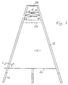
- FIG. 1 shows the box housing in the form of a three-sided, regular truncated pyramid with walls 10 made of translucent plastic.
- a tubular support 12 is provided, likewise made of translucent or transparent material.
- each carrier is glued or potted with the abutting edges of the walls 10, and a transparent plastic profile inserted into the millings of the walls connects the two walls in a form-fitting manner.
- the cavity between the profile 14, the walls 10 and the support 12 is potted with transparent material, so that an acoustically optimal, yet stable construction is realized.
- a tweeter loudspeaker 20 is fastened on a frame 18 and a mid-range loudspeaker 22 underneath it; underneath both there is an insulating layer 24 made of wadding or the like.
- the carriers 12 extend beyond the edges 16 and carry a spherical shell-shaped reflector 28, which ensures that the sound waves emitted by the loudspeakers 20 and 22 are deflected and distributed uniformly all around. With this principle, the optimal speaker tuning is achieved by actively controlling the speakers 20 and 22.
- a triangular base plate 32 is inserted just above the lower horizontal edge 30 of the walls and carries a low-frequency loudspeaker above a central, round cutout 34, which radiates downwards.
- a triangular hard foam plate 38 elastically bonded flush with the inside edges of the housing; for example with a foam surround; which, when fitted, serves as a passive membrane and increases the membrane area by a considerable amount. It can be seen that the completely centrally symmetrical structure must result in a correspondingly completely uniform radiation characteristic.
- a light source for example a UV light tube, is preferably arranged between the upper and the lower loudspeaker group, the base plate being able to serve as a support. Since such light sources are known per se, the illustration has been omitted in the drawing. However, it is worth mentioning that the color of the loudspeaker box can be changed as desired with little effort, for example by inserting differently colored, fluorescent rods.
- a crossover is also housed on the base plate, which contains and controls the output stages for the active high-mid-range unit and supplies the bass system directly with the audio signal.
- the carriers 12 are tubular and closed at the upper end.
- Round plastic rods 42 are inserted into these carriers, which are supported at the upper end on a spiral spring 44 which is fastened to the upper, closed end of the carrier.
- the speaker is suspended freely and is acoustically decoupled from the base.
- a foam block or another spring element can also be used instead of the coil spring.
Landscapes
- Health & Medical Sciences (AREA)
- Otolaryngology (AREA)
- Physics & Mathematics (AREA)
- Engineering & Computer Science (AREA)
- Acoustics & Sound (AREA)
- Signal Processing (AREA)
- Details Of Audible-Bandwidth Transducers (AREA)
- Obtaining Desirable Characteristics In Audible-Bandwidth Transducers (AREA)
Description
- Die Erfindung betrifft eine Lautsprecherbox. Lautsprecherboxen bestehen üblicherweise aus einem oft regelmäßig, manchmal unregelmäßig geformten Gehäuse, an bzw. auf dem im allgemeinen zwei, drei oder auch mehr Lautsprecher angeordnet sind.
- US-A-3,500,953 offenbart eine Lautsprecherbox in Form eines oben und unten offenen, zylindrischen oder kugelförmigen Gehäuses. Nahe der unteren Öffnung ist ein vertikal abwärts strahlender Tiefton-Lautsprecher angebracht, und nahe der oberen Öffnung ist ein vertikal aufwärts abstrahlender Hochton-Lautsprecher angebracht, über welchem sich ein verstellbarer, kugelschalenförmiger Reflektor befindet.
- DE-A-3 721 886 offenbart eine Lautsprecherbox in Form eines vier- oder fünfseitigen Pyramidenstumpfes, auf dessen Wandungen die Lautsprecher senkrecht zu deren Ebene Abstrahlend angeordnet sind.
- DE-A-2 441 950 offenbart ein Lautsprecherboxengehäuse aus durchscheinendem Material.
- Aufgabe der Erfindung ist es, einerseits eine akustisch hochwertige Lautsprecherbox zu schaffen, der man andererseits aber nicht ihre eigentliche Funktion ansehen kann, indem sie als dekorativer Beleuchtungskörper wirkt.
- Ausgehend von einer Lautsprecherbox in Form eines oben und unten offenen Gehäuses, einem nahe der unteren Öffnung angeordneten, vertikal abwärts strahlenden Tiefton-Lautsprecher und mindestens einem, nahe der oberen Öffnung angeordneten vertikal aufwärts strahlenden Mittel-/Hochtonlautsprecher wird diese Aufgabe gemäß der Erfindung dadurch gelöst, daß das Gehäuse die Form eines Pyramidenstumpfes mit Wandungen aus lichtdurchlässigem Kunststoff aufweist und daß im Gehäuseinnenraum eine Lichtquelle angeordnet ist.
- Vorzugsweise ist das Gehäuse mit Federbeinen versehen, die es von einer Standfläche akustisch entkoppeln.
- Ein bevorzugtes Ausführungsbeispiel der Lautsprecherbox nach der Erfindung ist in den beigefügten Zeichnungen weitgehend schematisch dargestellt und wird nachstehend im einzelnen beschrieben.
- Fig. 1
- zeigt die Box in Seitenansicht;
- Fig. 2
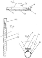
- zeigt in Seitenansicht die Anordnung des Tiefton-Lautsprechers;
- Fig. 3
- zeigt einen Teilschnitt nach Linie 3-3 in Fig. 1;
- Fig. 4
- zeigt den Aufbau eines Boxenfußes.
- Man erkennt in Fig. 1 das Boxengehäuse in Form eines dreiseitigen, regelmäßigen Pyramidenstumpfes mit Wandungen 10 aus lichtdurchlässigem Kunststoff. In den Eckbereichen, wo jeweils zwei Wandungen aneinandergrenzen, ist jeweils ein rohrförmiger Träger 12 vorgesehen, ebenfalls aus lichtdurchlässigem oder transparentem Material. Wie Fig. 3 erkennen läßt, ist jeder Träger mit den anstoßenden Kanten der Wandungen 10 verklebt bzw. vergossen, und ein in die Fräsungen der Wandungen eingeschobenes, transparentes Kunststoffprofil verbindet die beiden Wandungen formschlüssig. Der Hohlraum zwischen dem Profil 14, den Wandungen 10 und dem Träger 12 ist mit transparentem Material vergossen, so daß eine akustisch optimale, gleichwohl stabile Konstruktion realisiert wird.
- Dicht unter der oberen horizontalen Endkante 16 der Wandungen 10 ist, im Gehäuseinneren, auf einem Rahmen 18 ein Hochton-Lautsprecher 20 und unter ihm ein Mittelton-Lautsprecher 22 befestigt; unter beiden befindet sich eine Dämmschicht 24 aus Polsterwatte oder dergleichen.
- Die Träger 12 reichen über die Kanten 16 hinaus und tragen einen kugelschalenförmigen Reflektor 28, der dafür sorgt, daß die von den Lautsprechern 20 und 22 abgestrahlten Schallwellen umgelenkt und ringsum gleichförmig verteilt werden. Die optimale Lautsprecherabstimmung gelingt bei diesem Prinzip durch aktive Ansteuerung der Lautsprecher 20 und 22.
- Dicht oberhalb der unteren horizontalen Kante 30 der Wandungen ist eine dreieckige Bodenplatte 32 eingefügt, die über einem mittigen, runden Ausschnitt 34 einen Tiefton-Lautsprecher trägt, welcher nach unten hin abstrahlt. Unter ihm ist, bündig mit den Gehäuseinnenkanten eine dreieckige Hartschaumplatte 38 elastisch verklebt; beispielsweise mit einer Schaumstoffsicke; die, so angebracht, als Passivmembrane dient und die Membranfläche um einen erheblichen Teil vergrößert. Man erkennt, daß aufgrund des völlig zentralsymmetrischen Aufbaus eine entsprechend völlig gleichförmige Abstrahlcharakteristik resultieren muß.
- Es ist, bevorzugt zwischen der oberen und der unteren Lautsprechergruppe, eine Lichtquelle angeordnet, beispielsweise eine UV-Lichtröhre, wobei die Bodenplatte als Abstützung dienen kann. Da solche Lichtquellen an sich bekannt sind, wurde in der Zeichnung auf die Darstellung verzichtet. Es ist allerdings erwähnenswert, daß auf diese Weise die Farbe der Lautsprecherbox mit geringem Aufwand, beispielsweise durch Einschieben verschiedenfarbig bunter, fluoreszierender Stäbe, beliebig verändert werden kann.
- Auf der Bodenplatte ist ferner eine Frequenzweiche untergebracht, die die Endstufen für die aktive Hoch-Mitteltoneinheit enthält und ansteuert und das Tieftonsystem unmittelbar mit dem Audiosignal versorgt.
- Wie in Fig. 4 ersichtlich, sind die Träger 12 rohrförmig und am oberen Ende geschlossen. In diese Träger werden runde Kunststoffstäbe 42 eingeschoben, die sich am oberen Ende auf einer Spiralfeder 44 abstützen, die am oberen, geschlossenen Ende des Trägers befestigt ist. Durch die richtige Abstimmung der Feder auf das Gewicht des Gehäuses ist die Lautsprecherbox so frei federnd aufgehängt und perfekt akustisch von der Standfläche entkoppelt. Es versteht sich, daß anstelle der Schraubenfeder auch ein Schaumstoffblock oder ein anderes Federelement verwendet werden kann.
Claims (6)
- Lautsprecherbox in Form eines oben und unten offenen Gehäuses, einem nahe der unteren Öffnung angeordneten, vertikal abwärts strahlenden Tiefton-Lautsprecher und mindestens einem, nahe der oberen Öffnungen angeordneten vertikal aufwärts abstrahlenden Mittel-/Hochtonlautsprecher (20, 22), dadurch gekennzeichnet, daß das Gehäuse die Form eines Pyramidenstumpfes mit Wandungen (10) aus lichtdurchlässigem Kunststoff aufweist und daß im Gehäuseinnenraum eine Lichtquelle angeordnet ist.
- Lautsprecherbox nach Anspruch 1 in Form eines dreiseitigen Pyramidenstumpfes.
- Lautsprecherbox nach Anspruch 1 oder 2 mit mindestens einem Schallreflektor (28) zum Umlenken der von den Lautsprechern erzeugten Schallwellen.
- Lautsprecherbox nach Anspruch 3 mit einem oberhalb des Mittel-/ Hochtonlautsprechers angeordneten kugel- oder kugelschalenförm igen Reflektor (28).
- Lautsprecherbox nach Anspruch 3 oder 4 mit einer unterhalb des senkrecht nach unten abstrahlenden Tiefton-Lautsprechers horizontal angeordneten, auf Lautsprechersystem und Gehäuseboden (32) abgestimmten Passivmembran (38).
- Lautsprecherbox nach einem der vorangehenden Ansprüche mit Federbeinen (42, 44).
Applications Claiming Priority (3)
| Application Number | Priority Date | Filing Date | Title |
|---|---|---|---|
| DE3923126A DE3923126A1 (de) | 1989-07-13 | 1989-07-13 | Lautsprecherbox |
| DE3923126 | 1989-07-13 | ||
| PCT/EP1990/001123 WO1991001074A1 (de) | 1989-07-13 | 1990-07-10 | Lautsprecherbox |
Publications (2)
| Publication Number | Publication Date |
|---|---|
| EP0482030A1 EP0482030A1 (de) | 1992-04-29 |
| EP0482030B1 true EP0482030B1 (de) | 1994-09-21 |
Family
ID=6384926
Family Applications (1)
| Application Number | Title | Priority Date | Filing Date |
|---|---|---|---|
| EP90910119A Expired - Lifetime EP0482030B1 (de) | 1989-07-13 | 1990-07-10 | Lautsprecherbox |
Country Status (4)
| Country | Link |
|---|---|
| EP (1) | EP0482030B1 (de) |
| AT (1) | ATE112125T1 (de) |
| DE (2) | DE3923126A1 (de) |
| WO (1) | WO1991001074A1 (de) |
Families Citing this family (5)
| Publication number | Priority date | Publication date | Assignee | Title |
|---|---|---|---|---|
| FR2687268B1 (fr) * | 1992-02-06 | 1997-05-30 | Olivier Colin | Enceinte acoustique omnidirectionnelle et procede de fabrication. |
| US5667839A (en) * | 1993-01-28 | 1997-09-16 | Collagen Corporation | Human recombinant collagen in the milk of transgenic animals |
| DE29705406U1 (de) * | 1997-03-25 | 1997-06-12 | Bünzow, Hans-Dieter, Dipl.-Ing. (FH), 91054 Erlangen | Gehäuse für einen Lautsprecher |
| AU2008324800B2 (en) | 2007-11-05 | 2014-03-27 | Astrazeneca Ab | Methods of treating scleroderma |
| WO2011042019A1 (en) * | 2009-10-07 | 2011-04-14 | Sl Audio A/S | Dipole loudspeaker with diffuse rear radiation |
Family Cites Families (5)
| Publication number | Priority date | Publication date | Assignee | Title |
|---|---|---|---|---|
| US3500953A (en) * | 1968-12-04 | 1970-03-17 | Uolevi L Lahti | Loudspeaker system |
| DE2441950B2 (de) * | 1974-09-02 | 1976-08-05 | Poensgen,Karl Otto, 8000 München | Lautsprechergehaeuse |
| EP0155266B1 (de) * | 1983-09-06 | 1991-03-20 | WOLCOTT, Henry Oliver | Lautsprecherstruktur |
| DE8717764U1 (de) * | 1987-07-02 | 1990-03-08 | Kellco Keller & Pfahls GmbH, 6053 Obertshausen | Lautsprecherbox |
| EP0340435A3 (de) * | 1988-04-01 | 1991-04-24 | Yamaha Corporation | Akustischer Apparat |
-
1989
- 1989-07-13 DE DE3923126A patent/DE3923126A1/de not_active Withdrawn
-
1990
- 1990-07-10 DE DE59007284T patent/DE59007284D1/de not_active Expired - Fee Related
- 1990-07-10 EP EP90910119A patent/EP0482030B1/de not_active Expired - Lifetime
- 1990-07-10 WO PCT/EP1990/001123 patent/WO1991001074A1/de not_active Ceased
- 1990-07-10 AT AT90910119T patent/ATE112125T1/de not_active IP Right Cessation
Also Published As
| Publication number | Publication date |
|---|---|
| DE59007284D1 (de) | 1994-10-27 |
| EP0482030A1 (de) | 1992-04-29 |
| DE3923126A1 (de) | 1991-01-17 |
| ATE112125T1 (de) | 1994-10-15 |
| WO1991001074A1 (de) | 1991-01-24 |
Similar Documents
| Publication | Publication Date | Title |
|---|---|---|
| DE29602961U1 (de) | Schall-Licht-Kombinationsgerät | |
| DE3720374C2 (de) | Lautsprechersystem | |
| EP0482030B1 (de) | Lautsprecherbox | |
| DE69708523T3 (de) | Geräuschabsorbierende Strukturen und daraus hergestellte Wände | |
| DE3327994C2 (de) | ||
| DE69938142T2 (de) | Verfahren zur tonwiedergabe und säulenlautsprecher | |
| DE2809052C2 (de) | ||
| DE4331959A1 (de) | Lautsprecherbox | |
| DE102021118205B4 (de) | Dunstabzugshaube mit Lautsprecher | |
| EP1052879A2 (de) | Flächenelement | |
| WO1994012002A1 (en) | Frount mounting for loudspeaker, and a piece of furniture or room furnishing equipped with such a front mounting | |
| DE2336416A1 (de) | Hifi-lautsprecheranordnung | |
| DE69125512T2 (de) | Tonausrüstung für einen Fernseher | |
| EP0847223A1 (de) | Kegelförmiger Lautsprechervorsatz und Lautsprecheranordnung mit so einem Lautsprechervorsatz | |
| DE19530743C1 (de) | Lautsprecherbox | |
| EP0520385A2 (de) | Anordnung von Lautsprechern | |
| DE10203168B4 (de) | Lautsprecherbox | |
| DE19834414C2 (de) | Gehäuse für einen Lautsprecher und Verfahren zu dessen Herstellung | |
| DE20116619U1 (de) | Lautsprecheranlage | |
| EP4376440A1 (de) | Lautsprecheranordnung | |
| DE10124646B4 (de) | Lautsprecherbox | |
| DE102013223950B4 (de) | Lautsprechergehäuse | |
| DE2904094A1 (de) | Akustische einfassung in form eines dekorativen elementes | |
| DE29916698U1 (de) | Lautsprechergehäuse mit Zweischallkanälen, welche besondere Formen haben und deren Öffnungen speziell angeordnet sind | |
| DE3823482A1 (de) | Lautsprecheranordnung |
Legal Events
| Date | Code | Title | Description |
|---|---|---|---|
| PUAI | Public reference made under article 153(3) epc to a published international application that has entered the european phase |
Free format text: ORIGINAL CODE: 0009012 |
|
| AK | Designated contracting states |
Kind code of ref document: A1 Designated state(s): AT BE CH DE DK ES FR GB IT LI LU NL SE |
|
| 17P | Request for examination filed |
Effective date: 19920424 |
|
| 17Q | First examination report despatched |
Effective date: 19940125 |
|
| GRAA | (expected) grant |
Free format text: ORIGINAL CODE: 0009210 |
|
| AK | Designated contracting states |
Kind code of ref document: B1 Designated state(s): AT BE CH DE DK ES FR GB IT LI LU NL SE |
|
| PG25 | Lapsed in a contracting state [announced via postgrant information from national office to epo] |
Ref country code: FR Effective date: 19940921 Ref country code: DK Effective date: 19940921 Ref country code: IT Free format text: LAPSE BECAUSE OF FAILURE TO SUBMIT A TRANSLATION OF THE DESCRIPTION OR TO PAY THE FEE WITHIN THE PRE;WARNING: LAPSES OF ITALIAN PATENTS WITH EFFECTIVE DATE BEFORE 2007 MAY HAVE OCCURRED AT ANY TIME BEFORE 2007. THE CORRECT EFFECTIVE DATE MAY BE DIFFERENT FROM THE ONE RECORDED.SCRIBED TIME-LIMIT Effective date: 19940921 Ref country code: GB Effective date: 19940921 Ref country code: ES Free format text: THE PATENT HAS BEEN ANNULLED BY A DECISION OF A NATIONAL AUTHORITY Effective date: 19940921 Ref country code: NL Effective date: 19940921 Ref country code: BE Effective date: 19940921 |
|
| REF | Corresponds to: |
Ref document number: 112125 Country of ref document: AT Date of ref document: 19941015 Kind code of ref document: T |
|
| REF | Corresponds to: |
Ref document number: 59007284 Country of ref document: DE Date of ref document: 19941027 |
|
| PG25 | Lapsed in a contracting state [announced via postgrant information from national office to epo] |
Ref country code: SE Effective date: 19941221 |
|
| EN | Fr: translation not filed | ||
| NLV1 | Nl: lapsed or annulled due to failure to fulfill the requirements of art. 29p and 29m of the patents act | ||
| GBV | Gb: ep patent (uk) treated as always having been void in accordance with gb section 77(7)/1977 [no translation filed] |
Effective date: 19940921 |
|
| PG25 | Lapsed in a contracting state [announced via postgrant information from national office to epo] |
Ref country code: AT Effective date: 19950710 |
|
| PLBE | No opposition filed within time limit |
Free format text: ORIGINAL CODE: 0009261 |
|
| STAA | Information on the status of an ep patent application or granted ep patent |
Free format text: STATUS: NO OPPOSITION FILED WITHIN TIME LIMIT |
|
| PG25 | Lapsed in a contracting state [announced via postgrant information from national office to epo] |
Ref country code: LU Free format text: LAPSE BECAUSE OF NON-PAYMENT OF DUE FEES Effective date: 19950731 Ref country code: LI Effective date: 19950731 Ref country code: CH Effective date: 19950731 |
|
| 26N | No opposition filed | ||
| REG | Reference to a national code |
Ref country code: CH Ref legal event code: PL |
|
| PGFP | Annual fee paid to national office [announced via postgrant information from national office to epo] |
Ref country code: DE Payment date: 19961122 Year of fee payment: 7 |
|
| PG25 | Lapsed in a contracting state [announced via postgrant information from national office to epo] |
Ref country code: DE Free format text: LAPSE BECAUSE OF NON-PAYMENT OF DUE FEES Effective date: 19980401 |