EP0482074B1 - Verfahren zum testen einer bohrung - Google Patents
Verfahren zum testen einer bohrung Download PDFInfo
- Publication number
- EP0482074B1 EP0482074B1 EP90911289A EP90911289A EP0482074B1 EP 0482074 B1 EP0482074 B1 EP 0482074B1 EP 90911289 A EP90911289 A EP 90911289A EP 90911289 A EP90911289 A EP 90911289A EP 0482074 B1 EP0482074 B1 EP 0482074B1
- Authority
- EP
- European Patent Office
- Prior art keywords
- pressure
- probe
- deformation
- correction
- linked
- Prior art date
- Legal status (The legal status is an assumption and is not a legal conclusion. Google has not performed a legal analysis and makes no representation as to the accuracy of the status listed.)
- Expired - Lifetime
Links
- 238000010998 test method Methods 0.000 title abstract 2
- 239000000523 sample Substances 0.000 claims abstract description 70
- 239000012528 membrane Substances 0.000 claims description 21
- 238000005259 measurement Methods 0.000 claims description 20
- 238000000034 method Methods 0.000 claims description 19
- 239000012530 fluid Substances 0.000 claims description 17
- 238000006243 chemical reaction Methods 0.000 claims description 15
- 238000012937 correction Methods 0.000 claims description 12
- 238000012360 testing method Methods 0.000 claims description 11
- XLYOFNOQVPJJNP-UHFFFAOYSA-N water Substances O XLYOFNOQVPJJNP-UHFFFAOYSA-N 0.000 claims description 3
- 230000008859 change Effects 0.000 claims description 2
- 230000002441 reversible effect Effects 0.000 claims description 2
- 238000010008 shearing Methods 0.000 claims description 2
- 239000002689 soil Substances 0.000 claims 5
- 230000003247 decreasing effect Effects 0.000 claims 1
- 238000010586 diagram Methods 0.000 description 7
- 239000007788 liquid Substances 0.000 description 7
- 230000003068 static effect Effects 0.000 description 6
- 230000009471 action Effects 0.000 description 5
- 230000008569 process Effects 0.000 description 5
- 238000005553 drilling Methods 0.000 description 4
- 230000004224 protection Effects 0.000 description 4
- 239000004459 forage Substances 0.000 description 3
- 238000009434 installation Methods 0.000 description 3
- 229920000297 Rayon Polymers 0.000 description 2
- 230000006872 improvement Effects 0.000 description 2
- 239000002184 metal Substances 0.000 description 2
- 238000012545 processing Methods 0.000 description 2
- 239000002964 rayon Substances 0.000 description 2
- 240000008042 Zea mays Species 0.000 description 1
- 239000011248 coating agent Substances 0.000 description 1
- 238000000576 coating method Methods 0.000 description 1
- 238000013461 design Methods 0.000 description 1
- 230000010354 integration Effects 0.000 description 1
- 235000012830 plain croissants Nutrition 0.000 description 1
- 239000011435 rock Substances 0.000 description 1
Images


Classifications
-
- E—FIXED CONSTRUCTIONS
- E02—HYDRAULIC ENGINEERING; FOUNDATIONS; SOIL SHIFTING
- E02D—FOUNDATIONS; EXCAVATIONS; EMBANKMENTS; UNDERGROUND OR UNDERWATER STRUCTURES
- E02D1/00—Investigation of foundation soil in situ
- E02D1/02—Investigation of foundation soil in situ before construction work
- E02D1/022—Investigation of foundation soil in situ before construction work by investigating mechanical properties of the soil
-
- E—FIXED CONSTRUCTIONS
- E21—EARTH OR ROCK DRILLING; MINING
- E21B—EARTH OR ROCK DRILLING; OBTAINING OIL, GAS, WATER, SOLUBLE OR MELTABLE MATERIALS OR A SLURRY OF MINERALS FROM WELLS
- E21B49/00—Testing the nature of borehole walls; Formation testing; Methods or apparatus for obtaining samples of soil or well fluids, specially adapted to earth drilling or wells
- E21B49/006—Measuring wall stresses in the borehole
Definitions
- the invention relates to tests carried out from a borehole to determine the mechanical characteristics of the ground in elasticity and plasticity, thanks to a device of the type "pressuremeter", which was patented in France under the number 1.117.983, on January 19, 1955, by Mr. Louis Ménard. This device has been perfected and patented under the number 1.234.756, the 05.15.1959 by Mr. Louis Ménard, in particular with regard to the different parts of the "pressuremeter".
- Such tests successively include measuring the vacuum deformation of the probe, then the measurement of the deformation of the ground in drilling, finally the establishment of a pressure graph volume which represents the resistance of the ground at a given level.
- These tests are carried out with a probe which descended to a determined level of the borehole. This probe is then filled with liquid. From the surface, successively increasing pressure stages are applied. For each of these stages, the deformation of the probe is measured at time intervals croissants.
- the object of this invention is to avoid these drawbacks in the case of a floor, in providing more detailed and precise information on the different layers in the field, while only using commonly used devices for measurements.
- the invention provides an improvement to the test methodology, by introducing into the field loading sequence, one or more unloading cycles reloading, on which we can consider that the deformations are elastic. We thus frees itself from the plastic strain component which is one of the variables of the linear relation between the pressure and the deformation of the probe during a monotonous loading.
- the invention provides an improvement to the pressure determination technique in the field, by introducing a set of corrections that take into account the geometry discovered that the static balance of the terrain around the probe is determined within elasticity and plasticity conditions of the ground.
- a borehole (3) crosses a piece of land.
- the part of the drilling corresponding to the level of the probe can be left uncovered without any coating. the remaining part of the borehole can either be cased or left bare.
- a unit control (1) is placed on the surface, and connected by electric pipes (2) or hydraulic to the probe. Via the control unit (1), a pressurization of the probe (4). This loads the ground and deforms.
- a measure of deformation is done along the measurement cell, and is materialized by either a measurement local electrical or hydraulic system at the probe (4), either by electrical measurement or hydraulic corresponding to a liquid level in the control unit (1).
- the unit of control (1) supplies the probe, receives and processes the information coming from the probe if necessary until the reaction pressure graphs are fully established of the ground, deformation of the probe.
- These measuring devices can preferably be connected to each other to form a single probe lowered into the borehole at one time. However, these instruments can also be used separately, each in combination with the control unit.
- fluid pressure and deformation of the probe using the devices described above and with reference to a level selected from the well.
- the strain measurement is carried out in the measuring cell at increasing time intervals.
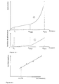
- the curve in Figure 2 was obtained for measurements of deformation of the probe, 15 seconds, 30 seconds, 1 minute after application of the pressure. This timescale is purely indicative and any other progression can be used.
- a drilling loading test is carried out beforehand at a level little different from the chosen level, so as to determine the creep pressure, which corresponds to the end of the linear relationship between the pressure and the deformation. , and the beginning of the non-linear relationship between pressure and strain.
- the probe is then placed at the chosen level and a loading is imposed in successive stages according to the method indicated above.
- the curve indicates at point A, bringing the probe into contact with the ground. From point A to point D which corresponds to the creep pressure previously defined, the relationship is linear between the pressure applied and the deformation of the probe.
- the creep pressure must always be higher than the highest possible pressure during the cycle, that is to say at point B. From point B which precedes point D, one proceeds by successive stages of unloading, until point E.
- the pressures imposed on the probe are corrected, and the deformations, to reduce to a value of the average reaction pressure of the ground and to an average deformation, along the measurement cell.
- reaction pressure of the ground, outside the probe static pressure which corresponds to the height z of the water table above of the probe.
- reaction pressure of the ground is measured, from the pressure imposed on the fluids internal to the probe (4) considering the static balance of the membrane (7) under the action of the stresses of the internal fluids (8) and the ground (9).
- the difference between the internal and external rays works by reducing the pressure.
- the reaction pressure of the ground is measured, from the pressure imposed on the internal fluids of the probe considering the static balance of the membrane under the action of stresses.
- the difference between the deformable length (10) of the probe on which the field reaction acts, and the length of the probe charged by the fluids internal (12) works by reducing pressure.
- the probe (4) can be protected by a split tube (11) which further reduces the pressure.
- reaction pressure of the ground is measured, from the pressure imposed on the internal fluids of the probe considering the static balance of the membrane under the action of stresses.
- the possible pressure difference between the liquid (14) and gas (13), or between the fluids actuating the measuring (6) and guard cells (5), is taken into account in the overall balance of the membrane.
- the deformation is measured along the measurement cell (15), taking into account the mean value of the deformation of the probe, which is a function of the distance from the ends.
- the deformation is maximum at the center of the probe, and zero at the extremities.
- the different stages of the process are represented on the flow diagram of FIG. 13.
- the first measurement block consists of measuring the deformation force when empty of the probe.
- the second and third blocks repeated sequentially, constitute the measure itself.
- the correction blocks correspond to the calculations presented above and constitute a processing of the measurement which makes it possible to obtain the corrected pressure and deformation of the terrain and a curve similar to that shown in Figure 3.
- the corrected pressure and strain results, as well as pressure and pressure variation as a function of time, are represented in FIG. 14.
- the creep pressure P f is determined as the change in slope on the pressure strain variation graph (b), or on the pressure strain rate graph at constant imposed pressure.
- P f corresponds to the end of the linear relation pressure deformation (at point D of figure 3) and to the beginning of the nonlinear relation between pressure and deformation (a).
Landscapes
- Life Sciences & Earth Sciences (AREA)
- Engineering & Computer Science (AREA)
- Mining & Mineral Resources (AREA)
- General Life Sciences & Earth Sciences (AREA)
- Geology (AREA)
- Structural Engineering (AREA)
- Environmental & Geological Engineering (AREA)
- Paleontology (AREA)
- Civil Engineering (AREA)
- General Engineering & Computer Science (AREA)
- Analytical Chemistry (AREA)
- Physics & Mathematics (AREA)
- Soil Sciences (AREA)
- Fluid Mechanics (AREA)
- Chemical & Material Sciences (AREA)
- Geochemistry & Mineralogy (AREA)
- Force Measurement Appropriate To Specific Purposes (AREA)
- Investigating Strength Of Materials By Application Of Mechanical Stress (AREA)
- Silver Salt Photography Or Processing Solution Therefor (AREA)
- Investigation Of Foundation Soil And Reinforcement Of Foundation Soil By Compacting Or Drainage (AREA)
- Sampling And Sample Adjustment (AREA)
Claims (5)
- Bohrtestverfahren, gekennzeichnet daduch, daß die Korrekturphase der Meßwerte aus folgenden Gängen besteht:Korrektur des Druckwerts um den Leerverformungswert der Sonde;Korrektur des Druckwerts um den Wert des hydraulischen Höhenunterschieds;Korrektur des Druckwerts um den Wert der Grundwasserdicke;Korrektur des Druckwerts aufgrund des Einflusses der Membranendicke;Korrektur des Druckwerts aufgrund des Einflusses des Längenunterschieds zwischen dem verformbaren Teil der Sonde und dem von Flüssigkeiten belasteten Teil;Korrektur des Druckwerts aufgrund des Einflusses des Druckunterschiedes zwischen den benutzten Flüssigkeiten;Korrektur des Druckwerts aufgrund des Einflusses der elastischen und der plastischen Bodenreaktion;Korrektur des Verformungswerts um den Wert der Rohverformung;Korrektur des Verformungswerts um den Einfluß durch den Unterschied zwischen Gesamtverformung der Sonde und deren durchschnittlicher Verformung im Meßteil.
- Verfahren gemäß Beanspruchung 1, bei welchem die Neigung der linearen Relation zwischen korrigierten Druck- und Verformungswerten errechnet wird, wie sie im umkehrbaren und elastischen Belastung-Entlastungszyklus ermittelt wurden, wodurch der Schermodul des Bodens errechnet werden kann.
- Verfahren nach Beanspruchung 1, bei welchem der Kriechdruck ermittelt wird entweder an der geänderten Neigung der Druck- Verformungsschwankungen-Kurve mit korrgierten Werten oder am Übergang vom linearen zum nicht linearen Teil der Druck-Verformung-Kurve mit korrigierten Werten, oder beides gleichzeitig.
- Verfahren gemäß Beanspruchungen 1 und 3, bei welchem der innere Reibewinkel des Bodens ermittelt wird aufgrund der Neigung der Geraden, durch die die korrigierten Druck- und Verformungswerte für Druckwerte jenseits des Kriechdruckwerts verbunden werden.
- Verfahren nach Beanspruchungen 1, 3 und 4, bei welchem die unterschiedlichen Werte des inneren Reibewinkels je nach wachsender oder abnehmender Tiefe der durchgeführten Versuche auf einem Blatt Papier ermitttelt werden.
Applications Claiming Priority (3)
| Application Number | Priority Date | Filing Date | Title |
|---|---|---|---|
| FR8909674A FR2649753B1 (fr) | 1989-07-12 | 1989-07-12 | Procede d'essai de forage |
| FR8909674 | 1989-07-12 | ||
| PCT/FR1990/000508 WO1991000951A1 (fr) | 1989-07-12 | 1990-07-05 | Procede d'essai de forage |
Publications (2)
| Publication Number | Publication Date |
|---|---|
| EP0482074A1 EP0482074A1 (de) | 1992-04-29 |
| EP0482074B1 true EP0482074B1 (de) | 1998-03-11 |
Family
ID=9383902
Family Applications (1)
| Application Number | Title | Priority Date | Filing Date |
|---|---|---|---|
| EP90911289A Expired - Lifetime EP0482074B1 (de) | 1989-07-12 | 1990-07-05 | Verfahren zum testen einer bohrung |
Country Status (5)
| Country | Link |
|---|---|
| EP (1) | EP0482074B1 (de) |
| AT (1) | ATE163989T1 (de) |
| DE (1) | DE69032132D1 (de) |
| FR (1) | FR2649753B1 (de) |
| WO (1) | WO1991000951A1 (de) |
Families Citing this family (4)
| Publication number | Priority date | Publication date | Assignee | Title |
|---|---|---|---|---|
| FR2798698B1 (fr) * | 1999-09-22 | 2001-11-02 | Gaiatech | Procede et appareil d'essai de terrain a partir d'un forage |
| RU2188320C1 (ru) * | 2001-01-22 | 2002-08-27 | Овчинников Марат Николаевич | Способ определения распределения давления и границ неоднородностей пласта (варианты) |
| FR2895011B1 (fr) * | 2005-12-15 | 2008-03-07 | Fugro Geotechnique Sa | Pressiometre de precision automatise |
| FR2914419B1 (fr) * | 2007-03-30 | 2009-10-23 | Datc Europ Sa | Dispositif de protection d'une sonde geotechnique ou geophysique |
Family Cites Families (4)
| Publication number | Priority date | Publication date | Assignee | Title |
|---|---|---|---|---|
| FR1402119A (fr) * | 1964-04-30 | 1965-06-11 | Electricite De France | Appareil d'essai du comportement mécanique statique d'un matériau à profondeur variable à partir d'un forage |
| FR2481453A1 (fr) * | 1980-04-25 | 1981-10-30 | Sev I Stroite | Procede de determination des caracteristiques de deformabilite des materiaux de construction et des sols |
| EP0146324A3 (de) * | 1983-12-20 | 1986-07-09 | Shosei Serata | Verfahren und Vorrichtung zum Messen in situ von Erdspannungen und Eigenschaften durch Anwendung einer Bohrlochsonde |
| FR2583876B1 (fr) * | 1985-06-21 | 1988-06-03 | Sopena | Procede et dispositif de mesure des caracteristiques de cisaillement d'un sol |
-
1989
- 1989-07-12 FR FR8909674A patent/FR2649753B1/fr not_active Expired - Lifetime
-
1990
- 1990-07-05 WO PCT/FR1990/000508 patent/WO1991000951A1/fr not_active Ceased
- 1990-07-05 AT AT90911289T patent/ATE163989T1/de active
- 1990-07-05 EP EP90911289A patent/EP0482074B1/de not_active Expired - Lifetime
- 1990-07-05 DE DE69032132T patent/DE69032132D1/de not_active Expired - Lifetime
Also Published As
| Publication number | Publication date |
|---|---|
| FR2649753A1 (fr) | 1991-01-18 |
| ATE163989T1 (de) | 1998-03-15 |
| DE69032132D1 (de) | 1998-04-16 |
| EP0482074A1 (de) | 1992-04-29 |
| FR2649753B1 (fr) | 1991-10-11 |
| WO1991000951A1 (fr) | 1991-01-24 |
Similar Documents
| Publication | Publication Date | Title |
|---|---|---|
| EP3411668B1 (de) | Verfahren zur überwachung des thermomechanischen verhaltens einer tiefseeleitung zum transport von unter hohem druck stehenden flüssigkeiten | |
| OA10237A (fr) | Procédé et dispositif permettant d'évaluer la perméabilité d'un milieu rocheux. | |
| EP0816629B1 (de) | Verfahren und Einrichtung zur Echtzeit-Einschätzung von mindestens eines Parameters, der mit dem Bohrfortschritt eines Bohrwerkzeuges zusammenhängt | |
| EP0126010B1 (de) | Vorrichtungen zur Bestimmung der Volumenveränderungen einer verformbaren und aufblasbaren Zelle welche in den Boden gedrückt ist und welche Innendruckgradienten unterworfen wird | |
| EP0482074B1 (de) | Verfahren zum testen einer bohrung | |
| FR3069324B1 (fr) | Penetrometre statique et procede de mesure associe | |
| FR2798698A1 (fr) | Procede et appareil d'essai de terrain a partir d'un forage | |
| FR3100326A1 (fr) | Appareil de mesure du périmètre d’un objet déformable, utilisation de l’appareil pour la pléthysmographie par inductance ou sur un obturateur gonflable, dispositifs de mesure par mise en pression du sous-sol et par compression d’un échantillon de sol ou de roche | |
| EP4264172B1 (de) | Vorrichtung und verfahren zur messung des mechanischen spiels in einer hydraulikleitung | |
| EP3914882A1 (de) | System und verfahren zur messung des füllstandes eines fluidbehälters mittels akustischer wellen | |
| CN107560595A (zh) | 建筑物及地质沉降监测方法 | |
| CN111722298B (zh) | 一种地下水埋藏类型综合判定方法 | |
| CA2058981A1 (fr) | Procede et dispositif de mesure in situ des caracteristiques de gonflement d'un sol | |
| EP0720006A1 (de) | Verfahren und Vorrichtung zur nicht intrusiven Messung der Druckschwankungen einer Flüssigkeit innerhalb einer Kanalisation | |
| EP0705941B1 (de) | Pressiometer mit zwei Piezometer | |
| FR2817322A1 (fr) | Dispositif de mise en place et de maintien de capteurs de mesure autour d'une tuyauterie, son procede d'installation et dispositif de mesure de debit dans ladite tuyauterie | |
| WO2020089547A1 (fr) | Procede de mesure des proprietes elasto-plastiques d'un sol grace a un penetrometre statique | |
| EP0012061A1 (de) | Verfahren zur Feststellung und Bezeichnung von Brennstoffelementhüllenfehlern in Kernreaktoren | |
| WO2004029570A2 (fr) | Capteur de pression a reseau de bragg. | |
| Darras | Acquisition de mesures topographiques appliquée aux prospections géophysiques en milieu couvert | |
| FR3017155A1 (fr) | Procede de suivi d'une intervention dans un puits d'exploitation de fluide menage dans le sous-sol, et dispositif d'intervention associe | |
| FR2687475A1 (fr) | Procede et appareil de mesure de la masse volumique et de la densite des liquides. | |
| CA2792313C (fr) | Procede et dispositif de mesure des caracteristiques mecaniques du sol | |
| FR2520476A1 (fr) | Procede et dispositif pour l'obtention de donnees relatives a la position dans un plan vertical d'une conduite souple en cours d'enfouissement | |
| FR2792402A1 (fr) | Procede et installation de suivi de l'evolution d'une grandeur physique au cours du temps |
Legal Events
| Date | Code | Title | Description |
|---|---|---|---|
| PUAI | Public reference made under article 153(3) epc to a published international application that has entered the european phase |
Free format text: ORIGINAL CODE: 0009012 |
|
| AK | Designated contracting states |
Kind code of ref document: A1 Designated state(s): AT BE CH DE DK ES FR GB IT LI LU NL SE |
|
| 17P | Request for examination filed |
Effective date: 19920511 |
|
| RAP3 | Party data changed (applicant data changed or rights of an application transferred) |
Owner name: GAIATECH |
|
| 17Q | First examination report despatched |
Effective date: 19950126 |
|
| GRAG | Despatch of communication of intention to grant |
Free format text: ORIGINAL CODE: EPIDOS AGRA |
|
| GRAH | Despatch of communication of intention to grant a patent |
Free format text: ORIGINAL CODE: EPIDOS IGRA |
|
| GRAH | Despatch of communication of intention to grant a patent |
Free format text: ORIGINAL CODE: EPIDOS IGRA |
|
| GRAA | (expected) grant |
Free format text: ORIGINAL CODE: 0009210 |
|
| AK | Designated contracting states |
Kind code of ref document: B1 Designated state(s): AT BE CH DE DK ES FR GB IT LI LU NL SE |
|
| PG25 | Lapsed in a contracting state [announced via postgrant information from national office to epo] |
Ref country code: IT Free format text: LAPSE BECAUSE OF FAILURE TO SUBMIT A TRANSLATION OF THE DESCRIPTION OR TO PAY THE FEE WITHIN THE PRE;WARNING: LAPSES OF ITALIAN PATENTS WITH EFFECTIVE DATE BEFORE 2007 MAY HAVE OCCURRED AT ANY TIME BEFORE 2007. THE CORRECT EFFECTIVE DATE MAY BE DIFFERENT FROM THE ONE RECORDED.SCRIBED TIME-LIMIT Effective date: 19980311 Ref country code: AT Free format text: LAPSE BECAUSE OF FAILURE TO SUBMIT A TRANSLATION OF THE DESCRIPTION OR TO PAY THE FEE WITHIN THE PRESCRIBED TIME-LIMIT Effective date: 19980311 Ref country code: GB Free format text: LAPSE BECAUSE OF FAILURE TO SUBMIT A TRANSLATION OF THE DESCRIPTION OR TO PAY THE FEE WITHIN THE PRESCRIBED TIME-LIMIT Effective date: 19980311 Ref country code: NL Free format text: LAPSE BECAUSE OF FAILURE TO SUBMIT A TRANSLATION OF THE DESCRIPTION OR TO PAY THE FEE WITHIN THE PRESCRIBED TIME-LIMIT Effective date: 19980311 Ref country code: ES Free format text: THE PATENT HAS BEEN ANNULLED BY A DECISION OF A NATIONAL AUTHORITY Effective date: 19980311 |
|
| REF | Corresponds to: |
Ref document number: 163989 Country of ref document: AT Date of ref document: 19980315 Kind code of ref document: T |
|
| REG | Reference to a national code |
Ref country code: CH Ref legal event code: EP |
|
| REF | Corresponds to: |
Ref document number: 69032132 Country of ref document: DE Date of ref document: 19980416 |
|
| PG25 | Lapsed in a contracting state [announced via postgrant information from national office to epo] |
Ref country code: SE Free format text: LAPSE BECAUSE OF FAILURE TO SUBMIT A TRANSLATION OF THE DESCRIPTION OR TO PAY THE FEE WITHIN THE PRESCRIBED TIME-LIMIT Effective date: 19980611 Ref country code: DK Free format text: LAPSE BECAUSE OF FAILURE TO SUBMIT A TRANSLATION OF THE DESCRIPTION OR TO PAY THE FEE WITHIN THE PRESCRIBED TIME-LIMIT Effective date: 19980611 |
|
| PG25 | Lapsed in a contracting state [announced via postgrant information from national office to epo] |
Ref country code: DE Free format text: LAPSE BECAUSE OF FAILURE TO SUBMIT A TRANSLATION OF THE DESCRIPTION OR TO PAY THE FEE WITHIN THE PRESCRIBED TIME-LIMIT Effective date: 19980613 |
|
| PG25 | Lapsed in a contracting state [announced via postgrant information from national office to epo] |
Ref country code: LU Free format text: LAPSE BECAUSE OF NON-PAYMENT OF DUE FEES Effective date: 19980705 |
|
| PG25 | Lapsed in a contracting state [announced via postgrant information from national office to epo] |
Ref country code: LI Free format text: LAPSE BECAUSE OF NON-PAYMENT OF DUE FEES Effective date: 19980731 Ref country code: CH Free format text: LAPSE BECAUSE OF NON-PAYMENT OF DUE FEES Effective date: 19980731 Ref country code: BE Free format text: LAPSE BECAUSE OF NON-PAYMENT OF DUE FEES Effective date: 19980731 |
|
| NLV1 | Nl: lapsed or annulled due to failure to fulfill the requirements of art. 29p and 29m of the patents act | ||
| GBV | Gb: ep patent (uk) treated as always having been void in accordance with gb section 77(7)/1977 [no translation filed] |
Effective date: 19980311 |
|
| PLBE | No opposition filed within time limit |
Free format text: ORIGINAL CODE: 0009261 |
|
| STAA | Information on the status of an ep patent application or granted ep patent |
Free format text: STATUS: NO OPPOSITION FILED WITHIN TIME LIMIT |
|
| BERE | Be: lapsed |
Owner name: GAIATECH Effective date: 19980731 |
|
| 26N | No opposition filed | ||
| REG | Reference to a national code |
Ref country code: CH Ref legal event code: PL |
|
| PG25 | Lapsed in a contracting state [announced via postgrant information from national office to epo] |
Ref country code: FR Free format text: LAPSE BECAUSE OF NON-PAYMENT OF DUE FEES Effective date: 19990331 |
|
| REG | Reference to a national code |
Ref country code: FR Ref legal event code: ST |