EP0482199B1 - Procede de detection de caracteristiques de resine par machines de moulage par injection - Google Patents
Procede de detection de caracteristiques de resine par machines de moulage par injection Download PDFInfo
- Publication number
- EP0482199B1 EP0482199B1 EP91904802A EP91904802A EP0482199B1 EP 0482199 B1 EP0482199 B1 EP 0482199B1 EP 91904802 A EP91904802 A EP 91904802A EP 91904802 A EP91904802 A EP 91904802A EP 0482199 B1 EP0482199 B1 EP 0482199B1
- Authority
- EP
- European Patent Office
- Prior art keywords
- screw
- value
- resin
- molten resin
- molten
- Prior art date
- Legal status (The legal status is an assumption and is not a legal conclusion. Google has not performed a legal analysis and makes no representation as to the accuracy of the status listed.)
- Expired - Lifetime
Links
- 229920005989 resin Polymers 0.000 title claims abstract description 309
- 239000011347 resin Substances 0.000 title claims abstract description 309
- 238000000034 method Methods 0.000 title claims abstract description 101
- 238000001746 injection moulding Methods 0.000 title abstract description 19
- 230000008569 process Effects 0.000 claims abstract description 68
- 230000007246 mechanism Effects 0.000 claims abstract description 33
- 238000002347 injection Methods 0.000 claims description 82
- 239000007924 injection Substances 0.000 claims description 82
- 229920003002 synthetic resin Polymers 0.000 claims description 80
- 239000000057 synthetic resin Substances 0.000 claims description 80
- 238000001514 detection method Methods 0.000 claims description 19
- 230000000694 effects Effects 0.000 claims description 18
- 238000013213 extrapolation Methods 0.000 claims description 4
- 238000013461 design Methods 0.000 claims description 3
- 230000015572 biosynthetic process Effects 0.000 claims 1
- 238000004364 calculation method Methods 0.000 description 12
- 238000000465 moulding Methods 0.000 description 12
- 238000004519 manufacturing process Methods 0.000 description 7
- 238000005259 measurement Methods 0.000 description 7
- 230000008859 change Effects 0.000 description 4
- 230000006835 compression Effects 0.000 description 4
- 238000007906 compression Methods 0.000 description 4
- 239000000463 material Substances 0.000 description 4
- 239000008188 pellet Substances 0.000 description 4
- 238000004458 analytical method Methods 0.000 description 3
- 230000006870 function Effects 0.000 description 3
- 230000003044 adaptive effect Effects 0.000 description 2
- 239000000654 additive Substances 0.000 description 2
- 230000000996 additive effect Effects 0.000 description 2
- 230000002411 adverse Effects 0.000 description 1
- 230000006399 behavior Effects 0.000 description 1
- 210000000988 bone and bone Anatomy 0.000 description 1
- 238000012937 correction Methods 0.000 description 1
- 238000011038 discontinuous diafiltration by volume reduction Methods 0.000 description 1
- 238000013401 experimental design Methods 0.000 description 1
- 238000012886 linear function Methods 0.000 description 1
- 238000002844 melting Methods 0.000 description 1
- 230000008018 melting Effects 0.000 description 1
- 238000010309 melting process Methods 0.000 description 1
- 239000000203 mixture Substances 0.000 description 1
- 239000004033 plastic Substances 0.000 description 1
- 229920003023 plastic Polymers 0.000 description 1
- 238000004886 process control Methods 0.000 description 1
- 230000009467 reduction Effects 0.000 description 1
- 238000010008 shearing Methods 0.000 description 1
- 238000012360 testing method Methods 0.000 description 1
- 239000002699 waste material Substances 0.000 description 1
Images


Classifications
-
- B—PERFORMING OPERATIONS; TRANSPORTING
- B29—WORKING OF PLASTICS; WORKING OF SUBSTANCES IN A PLASTIC STATE IN GENERAL
- B29C—SHAPING OR JOINING OF PLASTICS; SHAPING OF MATERIAL IN A PLASTIC STATE, NOT OTHERWISE PROVIDED FOR; AFTER-TREATMENT OF THE SHAPED PRODUCTS, e.g. REPAIRING
- B29C45/00—Injection moulding, i.e. forcing the required volume of moulding material through a nozzle into a closed mould; Apparatus therefor
- B29C45/17—Component parts, details or accessories; Auxiliary operations
- B29C45/76—Measuring, controlling or regulating
- B29C45/7693—Measuring, controlling or regulating using rheological models of the material in the mould, e.g. finite elements method
-
- B—PERFORMING OPERATIONS; TRANSPORTING
- B29—WORKING OF PLASTICS; WORKING OF SUBSTANCES IN A PLASTIC STATE IN GENERAL
- B29C—SHAPING OR JOINING OF PLASTICS; SHAPING OF MATERIAL IN A PLASTIC STATE, NOT OTHERWISE PROVIDED FOR; AFTER-TREATMENT OF THE SHAPED PRODUCTS, e.g. REPAIRING
- B29C45/00—Injection moulding, i.e. forcing the required volume of moulding material through a nozzle into a closed mould; Apparatus therefor
- B29C45/17—Component parts, details or accessories; Auxiliary operations
- B29C45/20—Injection nozzles
- B29C45/23—Feed stopping equipment
-
- B—PERFORMING OPERATIONS; TRANSPORTING
- B29—WORKING OF PLASTICS; WORKING OF SUBSTANCES IN A PLASTIC STATE IN GENERAL
- B29C—SHAPING OR JOINING OF PLASTICS; SHAPING OF MATERIAL IN A PLASTIC STATE, NOT OTHERWISE PROVIDED FOR; AFTER-TREATMENT OF THE SHAPED PRODUCTS, e.g. REPAIRING
- B29C45/00—Injection moulding, i.e. forcing the required volume of moulding material through a nozzle into a closed mould; Apparatus therefor
- B29C45/17—Component parts, details or accessories; Auxiliary operations
- B29C45/46—Means for plasticising or homogenising the moulding material or forcing it into the mould
- B29C45/47—Means for plasticising or homogenising the moulding material or forcing it into the mould using screws
- B29C45/50—Axially movable screw
-
- B—PERFORMING OPERATIONS; TRANSPORTING
- B29—WORKING OF PLASTICS; WORKING OF SUBSTANCES IN A PLASTIC STATE IN GENERAL
- B29C—SHAPING OR JOINING OF PLASTICS; SHAPING OF MATERIAL IN A PLASTIC STATE, NOT OTHERWISE PROVIDED FOR; AFTER-TREATMENT OF THE SHAPED PRODUCTS, e.g. REPAIRING
- B29C45/00—Injection moulding, i.e. forcing the required volume of moulding material through a nozzle into a closed mould; Apparatus therefor
- B29C45/17—Component parts, details or accessories; Auxiliary operations
- B29C45/76—Measuring, controlling or regulating
- B29C45/77—Measuring, controlling or regulating of velocity or pressure of moulding material
Definitions
- the present invention relates to a method for detecting the resin property of plasticized synthetic resin in an injection moulder which has a flow path opening/closing mechanism in the passage between the cylinder of the moulder and the cavity of a mould so as to block the resin flow between the cylinder and the cavity, and to an injection control method for controlling the weight of the plasticized synthetic resin injected from the cylinder of the injection moulder to fill the cavity of the form, on the basis of the detected resin property.
- the molten resin temperature (T) as the PVT property, or the molten state such as flowability of resin indicated by the molten resin temperature (T) can also be indicated by the revolution or back-pressure of the screw, the time required for measuring the molten resin in the actual injection moulding, or a combination of some of these three factors. Therefore, the PVT property can be generalized by replacing the molten resin temperature (T) with the molten state (Z).
- an object of the present invention to solve the above problems in the resin property-based moulding process control method. Specifically, an object of the present invention is:
- the weight of the moulded articles are weighed to enable pmT characteristic curves to be developed, in denoting the weight of the moulded articles.
- the result of the learning phase are evaluated in that the quality characteristics of the moulded articles produced in the learning phase and those articles which achieve the quality desired in production are identified by the operator in the controller.
- the production phase is controlled by controlling the dwell pressure and time to maintain a combination of parameters to result in moulded articles which should have the desired quality characteristics.
- a resin property detection method for an injection moulder which has a flow path opening/closing mechanism between the cylinder of the injection moulder and the cavity of a mould so as to block the flow of the plasticized synthetic resin between the cylinder and the cavity wherein a screw of the injection moulder is rotated with the opening/closing mechanism closed to cause the screw to move back, is characterised in that the following two process stages are conducted sequentially, with plasticized synthetic resin of a specified molten resin state value Z in front of the screw:
- a resin property detection method for an injection moulder which has a flow path opening/closing mechanism between the cylinder of the injection moulder and the cavity of a mould so as to block the flow of plasticized synthetic resin between the cylinder and the cavity, wherein a screw of the injection moulder is rotated with the resin flow blocked to cause the screw to move back is characterised in that the following two process stagers are conducted sequentially, with plasticized synthetic resin of a specified molten resin state value Z in front do the screw Z:
- the resin property detection method of the present invention may include the steps of repeating the above first and second process stages under different molten state values Z and under different pushing force values p in the second process stage, and obtaining the relational formula for the molten resin pressure value P, the molten resin volume value and the molten state value Z through the approximation of the relation among the pushing force values p0 and p, the travel distance S T and the molten state value Z by using a specified functional equation.
- the molten resin specific volume value V can be obtained by proportional calculation from the molten resin volume value and molten resin specific volume value V calculated in the following procedure: First, the following three process stages are conducted sequentially with the above-mentioned molten state value Z of plasticized synthetic resin:
- the molten resin volume of the injected plasticized synthetic resin is obtained on the basis of the positional values of the screw at the first and second stop positions, and finally the molten resin specific volume value V is calculated from the obtained molten resin volume value and the weight value G.
- the true molten resin specific volume value V can be obtained by calculating the molten resin volume value by the following procedure:
- a resin property detection method for an injection moulder which has a screw in a cylinder of the injection moulder and a flow path opening/closing mechanism between the cylinder moulder and the cavity of a mould so as to block the flow of plasticized synthetic resin between the cylinder and the cavity is characterised in that the following three process stage are conducted sequentially with plasticized synthetic resin of various molten state values Z:
- the resin property of the plasticized synthetic resin presently used for injection moulding can be detected easily in the injection moulder installed at the injection moulding site. Moreover, the thus detected resin property can be utilized directly in controlling the actual injection moulding process at the site.
- the molten state value Z may be any value selected from among the molten resin temperature, the revolution or back-pressure of the screw, the time required for measuring resin, or a combination of some of these elements.
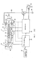
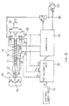
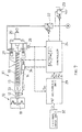
- an injection moulder 11 is connected by a nozzle 12 to a mould 10 in which a product is to be formed.
- a screw 19 is contained in the cylinder 13 of the injection moulder 11. Resin pellets supplied from a hopper 15 are melted and mixed in the cylinder 13, heated by a heater 14, to form a molten plasticized synthetic resin. The amount of molten resin is measured and then injected by the screw 19 through a flow passage 16 formed in the nozzle 12 and through a gate 17 into the cavity 18 of the mould 10. To melt and mix the resin pellets, the screw 19 is rotated by a screw-driving motor 20.
- the screw 19 and the screw-driving motor 20 are fixed on a base 21 which is moved laterally in the drawing, by means of pressurised oil supplied to a hydraulic piston device 27 through a pipe line 26 from a pressurised oil supply 25.
- an electromagnetic flow valve 22 and an electromagnetic pressure valve 23 are controlled by a controller 24.
- the movement of the screw 19 towards and away from the nozzle 12 to measure the amount of molten resin to be injected and to inject the measured ,molten resin into the cavity 18 of the mould 10 and the application of a specified pushing force to the screw 19 to impart a specified pressure to the molten resin in the cylinder 13 are all controlled through the base 21 by the pressurised oil supplied to the hydraulic piston device 27.
- the base 21 is engaged by a screw position detector 28 for detecting the positional value of the screw 19 in the cylinder 13 the positional value being "0" when the screw is at the left hand end, as seen in the drawing, and increasing as the screw 19 moves towards the right.
- the screw position detector 28 comprises a potentiometer and an encoder etc.
- the positional values of the screw 19 detected by the detector 28 minute by minute are sent to the controller 24 as well as to a PVZ arithmetic unit 29 which determines the PVZ property relation formula for plasticized synthetic resin when detecting the resin property P, V and Z referring respectively to the pressure, specific volume and temperature of the molten resin.
- the PVZ arithmetic unit 29 also operates a PV property relation formula to calculate the travel distance of the screw 19 and supplies the calculated result to the controller 24, thereby controlling the injection.
- the molten temperature value in the cylinder 13 detected by a resin temperature detector 30 is also transmitted, as the molten state value Z of the molten resin, to the PVZ arithmetic unit 29.
- the oil pressure value for the hydraulic piston device 27 is detected by an oil pressure detector 31 and is also sent to the arithmetic unit 29 as the pushing force applied to the screw 19 or the molten resin pressure value P in the cylinder 13.
- the measured volume of injected molten resin is inputted through an input unit 32 to the PVZ arithmetic unit 29 when detecting the resin property.
- the molten resin pressure value P, molten state value (molten resin temperature value) Z and other conditional values set for detecting the resin property are also input from the external input unit 32 through the PVZ arithmetic unit 29 to the controller 24.
- the target weight of the molten resin to be injected is also input form the external input unit 32 to the PVZ arithmetic unit 29.
- the flow passage 16 of the nozzle 12 contains a stop valve 33 as a flow path opening/closing mechanism of the injection moulder for interrupting the flow of molten resin flow.
- the stop valve 33 is operated through an operating rod 35 by an electromagnetic driving unit 34 which is controlled by the controller 24.
- a ring-shaped axially slidable valve plug 39 is provided between the conical end portion 36 and the flange projection 38 at the end of the spiral portion 37 of the screw 19.
- the slidable valve plug 39 is pressed against the flange projection 38, thus preventing the molten resin from flowing back to the right.
- the flange projection 38 and the ring-shaped slidable valve plug 39 constitute a check valve 40. Even if the screw position detector 28 reads "0" for the position of the screw 19, residual molten plasticized synthetic resin exists in the space between the front end of the screw 19 and the stop valve 33, or more specifically between the check valve 40 and the stop valve 33.
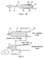
- the following three process stages are repeated with various molten state values (molten resin temperature values) Z1, Z2, Z3 ...., under a constant value p0 of the pressure of the molten resin to obtain values V01, V02, V03,... of the specific volume of the molten resin for the respective molten state values Z1, Z2, Z3, ... (see Fig. 2).
- the screw 19 is rotated to drive the molten plasticized synthetic resin towards the front end of the screw 19.
- the screw 19 is moved back because of the pressure of the molten resin prevailing in front of the screw 19.
- the screw 19 is moved back to a preliminarily set initial position, the amount of the molten resin to be injected is measured.
- the screw rotation is stopped.
- the arrival of the screw at the initial position is detected by the screw position detector 28 which sends the positional value of the screw 19 at the initial position to the controller 24.
- the controller 24 controls the pressurised oil supply to the hydraulic piston device 27 so that a specified pushing force value p0 is applied to the screw 19.
- the screw 19 makes a forward balancing movement, compressing the molten resin in front of the screw 19 with the aid of the function of the check valve 40.
- the molten resin pressure in the cylinder 13 increases.
- the forward movement of the screw 19 is stopped at a first stop position when the applied pushing force balances the pressure of the compressed molten resin.
- the screw position detector 28 detects the positional value of the screw 19 at the first stop position and outputs the value to the PVZ arithmetic unit 29.
- the molten resin pressure value P0 in front of the screw 19 corresponds to the pushing force value p0 applied to the screw 19.
- the stop valve 33 is opened, and the screw 19 is moved for a specified distance by the pushing force applied to the screw 19, so that molten resin is injected by an amount corresponding to the specified distance.
- the weight value G of the amount of injected molten resin is measured by an external measuring instrument.
- the measured weight value G is input from the external input unit 32 to the PVZ arithmetic unit 29.
- the stop valve 33 is closed again, and in this state, the oil pressure is controlled by the controller 24 in the same manner as in the first process stage so as to apply the specified pushing force value p0 to the screw 19.
- the screw 19 makes a forward or backward balancing movement, thus compressing the molten resin in front of the screw 19 correspondingly.
- the screw 19 stops at a second stop position when the applied pushing force balances the compressed molten resin pressure.
- the screw position detector 28 detects the positional value of the screw 19 at the second stop position and transmits the value to the PVZ arithmetic unit 29.
- the PVZ arithmetic unit 29 calculates the difference S T between the positional value of the first stop position and that of the second stop position, or in other words, the volume of the molten resin corresponding to the weight G of the injected molten resin.
- the calculated molten resin volume is divided by the weight G to obtain a molten resin specific volume value V0.
- the series of process stages is repeated for various molten state values (molten resin temperature values) Z1, Z2, Z3, ... under a constant specified pushing force value p0 (molten resin pressure value P0) to obtain the molten resin specific volume values V01, V02, V03, ....
- the screw 19 is rotated with the stop valve 33 closed.
- the screw 19 moves back and stops at a preliminarily set initial position while the molten resin at the molten state value Z0 is measured.
- a specified pushing force value p0 is applied to the screw 19 to move the screw 19 forward so that the molten resin is compressed.
- the screw 19 stops its forward movement at a first stop position when the applied pushing force balances the pressure of the compressed molten resin.
- the positional value of the screw 19 at the first stop position is detected by the screw position detector 28 and sent to the PVZ arithmetic unit 29. Other operations are the same as those in the first process stage of the first phase.
- a specified pushing force value p is applied to the screw 19 with the stop valve 33 remaining closed and the molten state value still at Z0. This time, the applied specified pushing force value p is increased gradually from p1 to p2 to p3 and so on, with the pushing force value p0 in the first process stage as a reference, thus gradually compressing the molten resin.
- the screw 19 makes a balancing movement and stops at a second, third, fourth or subsequent stop position, as shown in Fig.3. The positional value of each stop position is detected by the screw position detector 28 and sent to the PVZ arithmetic unit 29.
- the PVZ arithmetic unit 29 calculates the difference S T of the positional value at the second, third, fourth or subsequent stop position from the positional value at the first stop position to obtain the values of the reduction in the molten resin volume on the basis of the calculated difference. From each of the thus obtained molten resin volume reduction values and the molten resin specific volume values V01 (V02, V03,...) calculated in the first phase, molten resin specific volume values V11, V21, V31,... (V12, V22, V32,...; V13, V23, V33,...) are obtained by proportional calculation.
- This proportional calculation is based on the fact that, for the compressed molten resin of the same molten state value (molten resin temperature value) Z and of the same weight value G, the molten resin specific volume value V is obtained from the ratios of molten resin volume values in the case wherein the molten resin pressure value p0 (pushing force value p0) is changed to P1, P2, P3,... (pushing force value p1, p2, p3,).
- the series of calculation processes is repeated for each of the molten state values (molten resin temperature values) Z1, Z2, Z3,... under each of the pushing force values p1, p2, p3,... applied to the screw 19 (the molten resin pressure values P1, P2, P3,...), thereby obtaining the molten resin specific volume values V11, V21, V31,...; V12, V22, V32,...; V13, V23, V33,....
- the molten state value (molten resin temperature value) Z is changed by controlling the heater 14 by means of the controller 24.
- the residual molten resin volume must be corrected to obtain an accurate molten resin specific volume value V.
- the correction method is described below:
- each of the molten resin pressure values P0, P1, P2,..., each of the molten resin specific volume values V01, V02, V03,...; V11, V12, V13,...; V21, V22, V23,... and each of the molten state values (molten resin temperature value) Z1, Z2, Z3,... obtained in the first and second phases are substituted in the general formula for the PVZ property, to establish the PVZ property relation formula.
- V/V0 f(P/P0) (4)
- P, V are the given molten resin pressure value and molten resin specific volume value for the given molten resin pressure value P0
- V0 are the reference molten resin pressure value and molten resin specific volume value for the reference molten resin pressure value
- the above molten resin pressure values P and P0 and molten resin specific volume values V and V0 are given at the same molten state value (molten resin temperature value) Z.
- V V0 ⁇ exp ⁇ (b ⁇ Z + c) ⁇ ( ⁇ P/P0 ⁇ - 1) ⁇ (7)
- V0 ⁇ ' ⁇ Z n + ⁇ '' ⁇ Z n-1 + ... + ⁇ n' ⁇ Z + ⁇ ' wherein ⁇ ', ⁇ '', ... ⁇ n' , ⁇ ' are constants
- the PVZ property relation formula is established by repeating the following three process stages for each of the molten state values (molten resin temperature values) Z., Z2, Z3,....
- the screw 19 is rotated with the stop valve 33 closed, and stopped when it has moved back to a preliminarily set initial position. Then, pushing force values p S0 , p S1 , p S2 , ..., p Sn are applied sequentially to the screw 19 to compress the molten resin.
- the screw 19 makes a balancing movement and stops at a first stop position indicated by the positional value S S0 , S S1 , S S2 , ..., or S Sn , which is detected by the screw position detector 28 and sent to the PVZ arithmetic unit 29.
- Other operations are the same as those in the first process stage of the first phase in the first embodiment.
- a pushing force value p which is applied immediately before injection in the ordinary production process, is applied to the screw 19 and the stop valve 33 is opened, so that the molten resin of the weight for bone batch is injected into the cavity 18 of the mould 10 to form an actual product.
- a pushing force value p which is applied during the dwell following the injection in the ordinary production process, is applied to the screw 19 and the stop valve 33 is closed.
- the weight value G of the injected molten resin is measured by an external measuring instrument and input through the external Input unit 32 to the PVZ arithmetic unit 29.
- pushing force values p S0 , p S1 , p S2 , ..., p Sn are applied sequentially to the screw 19.
- the screw 19 makes a balancing movement and stops at a second stop position indicated by the positional value S F0 , S F1 , S F2 , ..., or S Fn , which is detected by the screw position detector 28 and sent to the PVZ arithmetic unit 29.
- Equation (11) is the PV property relation formula for a constant molten state value (molten resin temperature value) Z.
- the PVZ arithmetic unit 29 operates according to this equation (11) to establish the PV property relation formula for a constant molten state value (molten resin temperature value) Z.
- a similar process is repeated for each of the molten state values (molten resin temperature values) Z1, Z2, Z3,... to establish the PVZ property relation formula for each molten state value.
- the molten resin temperature value is used for the molten state value Z which indicates the molten state of plasticized synthetic resin.
- the revolution of the screw 19 during plasticization and measurement of the resin, the time required for the measurement, or the back-pressure value of the screw 19 may be used instead of the molten resin temperature value. Even if the revolution or back-pressure value of the screw 19 is constant, the time required for measurement tends to change with the ratio of the reclaimed resin content or of the additive content in the plasticized synthetic resin material etc.
- the back-pressure value of the screw 19 varies with the temperature of the pressurised oil supplied to the hydraulic piston device 27. This change in the back-pressure value can be identified by detecting the oil pressure for the hydraulic piston device 27 by the oil pressure detector 31.
- the revolution or back-pressure value of the screw 19 is to be detected at the time of changing the moulding condition
- the revolution or the value of the back-pressure value to be set for the value at the time of new moulding condition may be input through the external input unit 32 to the PVZ arithmetic unit 29.
- the similar PVZ property relation formula can be established in this case. Therefore, when a continuous moulding operation is started, the travel distance of the screw 19 to the position for injection may be calculated according to the PVZ property relation formula based on the revolution or back-pressure value detected, as a molten state value Z, during the continuous moulding process.
- V V0 ⁇ exp ⁇ a(Z) ⁇ ( ⁇ P/P0 ⁇ - 1) ⁇
- T the molten resin temperature value (molten state value Z) ⁇ 1
- ⁇ , R' are constants determined by the type of plasticized synthetic resin
- the values for the constants ⁇ 1, ⁇ and R' may be obtained by the following procedure: Firstly, the molten resin specific volume value V0 under a constant molten resin pressure value P0 and at a constant molten resin temperature value T0 is obtained in the same method as in the first phase of the first embodiment.
- the value for the constant ⁇ is obtained with the molten resin temperature value T varied.
- the molten resin volume value is obtained with the molten resin pressure value P set at P1, in the same method as in the second phase of the first embodiment, and the molten resin specific volume value V1 under the molten resin pressure value P1 is calculated from the above-mentioned molten resin specific volume value V0 by proportional calculation.
- the value for the constant ⁇ 1 can be calculated by the following equation:
- the values for the constants ⁇ and ⁇ 1 have been obtained, it is possible to calculate the value for the constant R' by equation (12).
- the values for the constants ⁇ , ⁇ 1 and R' may be obtained by the above procedures, if necessary.
- the molten resin temperature value T indicates the molten state such as flowability of the molten resin
- the molten resin temperature value T can be generalized as the molten state value Z by the following equation:
- the method of establishing the PVZ property relation formula by using Spencer & Gilmore's equation has been described.
- the PVZ property relation formula may be established by using the experimental analysis method according to the experimental design (multivariable sequential approximation).
- Embodiments of an injection control method are based on the PVZ property relation formula thus established by the above procedure. Prior to explaining each embodiment of the injection control method, the calculation formula used to obtain the travel distance of the screw 19 for injecting a constant weight value of molten resin is explained with reference to Fig. 5.
- molten resin pressure value P, positional value S of the screw 19 and molten resin specific volume value V immediately before injection and those during the dwell following the injection are set as follows:
- the positional values S I1 and S H1 of the screw 19 are based on the distance from the position of the screw 19 indicated by the positional value "0". These positional values S I1 and S H1 are corrected values based on the residual molten resin volume.
- the molten resin specific volume values V(P I1 ,Z1) and V(P H1 ,Z1) are obtained from the PVZ property relation formula that has been established in the aforementioned procedure on the basis of the molten resin temperature value (molten state value) Z and molten resin pressure values P I1 and P H1 detected by the resin temperature detector 30 and by the oil pressure detector 31, respectively, or on the basis of the molten state value (molten resin temperature value) Z1 and molten resin pressure values P I1 and P H1 to be set.
- the injection weight value G as the target weight value of a product, is input through the external input unit 32 to the PVZ arithmetic unit 29.
- the screw 19 is rotated and moves back while the amount of molten resin to be injected is measured. After the rotation of the screw 19 is stopped, a pushing force is applied to the screw 19.
- the screw position detector 28 detects the positional value S I1 of the screw 19 immediately before injection, with the stop valve 33 closed.
- the oil pressure detector 31 detects the molten resin pressure value P I1 (or pushing force value p I1 )
- the resin temperature detector 30 detects the molten resin temperature value (molten state value) Z1.
- the stop valve 33 is then opened so that injection is started.
- the screw 19 is moved forward, the cavity 18 of the mould 10 is filled with the injected molten resin.
- the molten resin pressure value P H1 (pushing force value p H1 ) during the dwell process following the injection is also detected by the oil pressure detector 31 and input to the PVZ arithmetic unit 29.
- the PVZ arithmetic unit 29 then calculates the travel distance S D of the screw 19 by equation (16), from the input positional value S I1 , molten resin pressure values P I1 and P H1 and molten resin temperature value (molten state value) Z1, on the basis of the PVZ property relation formula.
- the calculated travel distance S D is sent to the controller 24 where it is compared with the positional value provided by the screw position detector 28. When the travel distance S D is equal to the positional value, the controller 24 closes the stop valve 33, thus terminating the injection of the molten resin into the cavity 18 of the mold 10.
- the travel distance S D for injection of the resin of a constant weight value G can be obtained even if the molten resin pressure values P I1 and P H1 and the molten resin temperature value (molten state value) Z1 vary.
- the controller 24 controls the electromagnetic flow valve 22 and electromagnetic pressure valve 23 so that set molten resin pressure values P I1 and P H1 are obtained.
- the controller 24 also controls the heater 14 so that a set molten resin temperature value (molten state value) Z1 is obtained.
- the PVZ arithmetic unit 29 calculates the travel distance S D from the positional value S I1 of the screw 19 immediately before injection input from the screw position detector 28 and the molten resin pressure values P I1 and P H1 and molten resin temperature value (molten state value) Z1 set in the controller 24, on the basis of the PVZ property relation formula.
- the calculated travel distance S D is sent to the controller 24.
- Other operations are the same as those in the third embodiment.
- the latest molten resin pressures values P I1 and P H1 and molten resin temperature values (molten state value) Z1 detected are used for calculating the travel distance S D .
- the calculation may be based on the values of P I1 , P H1 and Z1 detected in the last injection operation or on the mean values of P I1 , P H1 and Z1 detected in the previous operations over a specified period.
- the molten resin temperature value is used as the molten state value Z in the third and fourth embodiments. Nevertheless, the revolution of the screw 19 during the plasticization and measurement process, the time required for the measurement or the back-pressure value of the screw 19 may be used for the molten state value Z.
- a shut-off valve may be provided at the gate 17 of the mould 10.
- the resin property is easily detected in an injection moulder installed at the injection moulding site by using the plasticized synthetic resin currently used for injection moulding.
- the resin property thus detected can be used directly for controlling the actual injection moulding process at the site. Therefore, the resin property detection method for an injection moulder according to the present invention is useful particularly where the property of the plasticized synthetic resin material varies with the ratio of reclaimed resin content or additive content.
Landscapes
- Engineering & Computer Science (AREA)
- Manufacturing & Machinery (AREA)
- Mechanical Engineering (AREA)
- Injection Moulding Of Plastics Or The Like (AREA)
Abstract
Claims (9)
- Procédé de détection de caractérisitiques de résine pour une machine de moulage à injection qui a un mécanisme d'ouverture/fermeture de voie de passage (33) entre le cylindre (13) de la machine de moulage à injection (11) et la cavité (18) d'un moule de manière à bloquer le passage de la résine synthétique plastifiée entre le cylindre (13) et la cavité (18), dans lequel une vis (19) de la machine de moulage à injection (11) est tournée avec le mécanisme d'ouverture/fermeture (33) fermé pour forcer la vis (19) à se déplacer vers l'arrière, caractérisé en ce que les deux étapes suivantes du procédé sont guidées de manière séquentielle, avec une résine synthétique plastifiée de valeur d'état de résine en fusion Z spécifiée devant la vis:(a) première étape du procédé comprenant les étapes, dans l'état fermé du mécanisme d'ouverture/fermeture (33) de la voie de passage pour bloquer le passage de la résine synthétique plastifiée, d'application d'une valeur de force de poussée de référence P₀ sur la vis (19) pour effectuer un mouvement d'équilibrage de la vis dans son état bloqué d'écoulement et d'obtention de la valeur de position de la vis (19) à la position d'arrêt de référence où la vis arrête son mouvement d'équilibrage, et(b) deuxième étape du procédé comprenant les étapes d'application d'une valeur de force de poussée P, différente de la force de poussée de référence P₀, à la vis (19) pour effectuer un mouvement d'équilibrage de la vis, d'obtention de la valeur de position de la vis (19) à la position où la vis arrête son mouvement d'équilibrage, et calcul de la distance de parcours ST de la position d'arrêt de référence de la vis; et en ce que une formule de relation pour la valeur de pression de résine en fusion P et la valeur du volume de résine en fusion avec la valeur d'état de résine en fusion Z spécifiée est obtenue à partir de l'approximation de la relation parmi les valeurs de forces de poussée P₀ et P et la distance de parcours ST en utilisant l'équation fonctionnelle:-

dans laquelle P₀ est la valeur de pression de référence de la résine en fusion
(valeur de force de poussée de référence P₀),
P est une valeur de pression de résine en fusion (valeur de force de poussée p) a est une constante. - Procédé de détection de caractérisitiques de résine pour une machine de moulage à injection qui a un mécanisme d'ouverture/fermeture (33) de voie de passage entre le cylindre (13) de la machine de moulage à injection (11) et la cavité (18) d'un moule de manière à bloquer le passage de la résine synthétique plastifiée entre le cylindre (13) et la cavité (11), dans lequel une vis (19) de la machine de moulage à injection (11) est tournée avec le passage de résine bloqué pour forcer la vis (19) à se déplacer vers l'arrière, caractérisé en ce que les deux étapes suivantes du procédé sont guidées de manière séquentielle, avec une résine synthétique plastifiée de valeur d'état de résine en fusion Z spécifiée devant la vis Z:(a) une première étape du procédé comprenant les étapes, dans l'état fermé du mécanisme d'ouverture/fermeture (13) de la voie de passage pour bloquer le passage de la résine synthétique plastifiée, d'application d'une valeur de force de poussée de référence P₀ à la vis (19) pour effectuer un mouvement d'équilibrage de la vis dans l'état bloqué de passage, et d'obtention de la valeur de position de à vis (19) à la position d'arrêt de référence où la vis arrête son mouvement d'équilibrage, et(b) deuxième étape de procédé comprenant les étapes d'application d'une valeur de force de poussée p, différente de la force de poussée de référence P₀, à la vis (19) pour effectuer un mouvement d'équilibrage de la vis, d'obtention de la valeur de position de la vis (19) à la position où la vis arrête son mouvement d'équilibrage, et de calcul de la distance de parcours ST depuis la position d'arrêt de référence de la vis; et lesdites première et deuxième étapes de procédé sont répétées sous différentes valeurs d'état de fusion Z, la valeur de force de poussée p devant être appliquée à la vis (19) étant variée dans la deuxième étape de procédé, et en ce que la formule de relation pour la valeur de pression de résine en fusion p, la valeur de volume de résine en fusion et la valeur d'état en fusion Z est obtenue par l'intermédiaire de l'approximation de la relation parmi les valeurs de force de poussée P₀ et p, la distance de parcours ST et la valeur d'état en fusion Z en utilisant l'équation fonctionnelle:-

₀ est la valeur de pression de référence de résine en fusion (valeur de force de poussée de référence P₀),
P est la valeur de pression de la résine en fusion (valeur de force de poussée p)
a (Z) est une constante fixée par la valeur d'état de la résine en fusion Z. - Procédé de détection de caractéristiques de résine pour une machine de moulage à injection selon les revendications 1 ou 2, comprenant en outre les étapes suivantes:
effectuer de manière séquentielle les trois étapes suivantes du procédé avec la résine synthétique plastifiée de ladite valeur d'état en fusion Z:(a) première étape du procédé dans laquelle la valeur de force de poussée P₀ ou p est appliquée à la vis (19) avec le mécanisme d'ouverture/fermeture (33) de voie de passage fermé pour bloquer le passage de la résine synthétique plastifiée, de manière à effectuer un mouvement d'équilibrage de la vis, et la valeur de position de la vis (19) à la première position d'arrêt où la vis arrête son mouvement d'équilibrage est obtenue,(b) deuxième étape du procédé dans laquelle le mécanisme d'ouverture/fermeture (33) de la voie de passage est ouvert afin de permettre à la résine synthétique plastifée de passer, et sous l'état disponible de passage, une force de poussée est exercée sur la vis (19) de manière à permettre à la résine synthétique plastifiée d'une valeur de poids G approprié d'être injectée, et(c) troisième étape du procédé dans laquelle le mécanisme d'ouverture/fermeture (33) de voie de passage est fermé après injection de la résine synthétique plastifiée de valeur de poids G pour bloquer le passage de la résine synthétique plastifiée, une force de poussée de la même valeur que celle de la première étape du procédé est exercée sur la vis (19) dans l'état bloqué de passage de manière à effectuer un mouvement d'équilibrage de la vis, et la valeur de position de la vis à la deuxième position d'arrêt où la vis arrête son mouvement d'équilibrage est obtenue;
calcul de la valeur de la résine en fusion de la résine synthétique plastifiée injectée en se basant sur des valeurs de position de la vis (19) à la première et seconde positions d'arrêt; et
obtention de la valeur de volume spécifique de la résine en fusion V à partir de la valeur du volume de résine en fusion ainsi calculée et de la valeur de poids G. - Procédé de détection de caractérisitiques de résine pour une machine de moulage à injection selon la revendication 1 ou 2, dans lequel ledit mécanisme d'ouverture/fermeture (33) de la voie de passage est une soupape d'arrêt prévue dans l'ajutage (12) de la machine de moulage à injection (11) et la valeur du volume résiduel de la résine synthétique plastifiée en fusion restante dans l'espace entre l'extrémité avant de la vis (19) et la soupape d'arrêt (33) est connue en tant que résitance caractéristique, dans lequel la valeur de volume de la résine de fusion résiduelle est transformée en une distance de parcours de la vis (19) et ajoutée à ladite distance de parcours ST, de la valeur de volume de résine synthétique plastifiée en fusion injectée étant obtenue à partir de la somme des distances de parcours.
- Procédé de détection de caractérisitiques de résine pour une machine de moulage à injection selon la revendication 1 ou 2, dans lequel ledit mécanisme d'ouverture/fermeture (33) de la voie de passage est une soupape d'arrêt prévue dans l'ajutage (12) de la machine de moulage à injection (11) et la valeur du volume résiduel de la résine synthétique plastifiée en fusion restante dans l'espace entre l'extrémité avant de la vis (19) et la soupape d'arrêt (33) est inconnue, et dans lequel le procédé comprend en outre les étapes suivantes:
application d'une valeur de force de poussée p spécifiée à la vis (19) à différentes positions sous l'état bloqué de passage, avec la soupape d'arrêt (33) fermée et avec la résine synthétique plastifiée de ladite valeur d'état en fusion Z;
calcul de la distance de parcours de la vis (19) depuis la dernière position d'arrêt à la position où la vis s'arrête suivant le mouvement d'équilibrage sous ladite valeur de force de poussée p spécifiée;
obtention de la valeur de position de la vis (19) à laquelle la distance de parcours de la vis est égale à zéro sous ladite valeur de force de poussée p, par l'extrapolation en se basant sur chaque position d'arrêt et sur la distance de parcours correspondante;
addition de la valeur de position obtenue à ladite distance de parcours ST; et
obtention de la valeur de volume de résine en fusion de la résine synthétique plastifiée injectée à partir de la distance de parcours ainsi obtenue par addition. - Procédé de détection de caractérisitiques de résine pour une machine de moulage à injection qui comporte une vis (19) dans un cylindre (13) de la machine de moulage à injection (11) et un mécanisme d'ouverture/fermeture (33) de voie de passage entre le cylindre (13 ) et la cavité (18) d'un moule de manière à bloquer le passage de la résine synthétique plastifiée entre le cylindre (13) et la cavité (18), caractérisé en ce que les trois étapes suivantes du procédé sont effectuées de manière séquentielle avec la résine synthétique plastifiée des différentes valeurs d'état en fusion Z:(a) première étape du procédé comprenant les étapes de fermeture du mécanisme d'ouverture/fermeture (33) de la voie de passage pour bloquer le passage de la résine synthétique plastifiée, et dans l'état bloqué de la voie de passage d'application de différentes valeurs de force de poussée p sur la vis (19) de manière à effectuer un mouvement d'équilibrage de la vis, et d'obtention de la valeur de position de la vis à la première position d'arrêt où la vis arrête son mouvement d'équilibrage sous chacune desdites différentes valeurs de force de poussée p,(b) deuxième étape du procédé comprenant les étapes d'ouverture du mécanisme d'ouverture/fermeture (33) de la voie de passage pour permettre à la résine synthétique plastifiée de passer, et dans l'état disponible d'écoulement, d'application d'une force de poussée sur la vis (19) afin de permettre à la résine synthétique plastifiée d'une valeur de poids G approprié d'être injectée, et(c) troisième étape du procédé comprenant les étapes de fermeture du mécanisme d'ouverture/fermeture (33) de la voie de passage après injection de la résine synthétique plastifiée de valeur de poids G pour bloquer le passage de la résine synthétique plastifiée, et dans l'état bloqué de passage, d'application desdites différentes valeurs de force de poussée p à la vis (19) de manière à effectuer le mouvement d'équilibrage de la vis, et d'obtention de la valeur de position de la vis à la seconde position d'arrêt où la vis arrête son mouvement d'équilibrage sous chacune desdites différentes valeurs de force de poussée p; en ce que la valeur de volume de résine en fusion de la résine synthétique plastifiée injectée est obtenue en se basant sur les valeurs de position de la vis (19) à la première et seconde positions d'arrêt sous chacune des nombreuses valeurs de force de poussée p pour chaque valeur d'état de fusion Z; et
en ce que la valeur de volume spécifique de résine en fusion V est calculée à partir de chacune des valeurs de volume de résine en fusion ainsi calculée et de ladite valeur de poids G, obtenant ainsi la formule de relation de caractéristiques PVZ pour la valeur de pression de résine en fusion P, la valeur de volume spécifique de résine en fusion V et la valeur de l'état en fusion Z. - Procédé de détection de caractéristiques de résine pour une machine de moulage à injection selon les revendications 1 à 6, dans lequel ladite valeur d'état en fusion Z est une valeur sélectionnée parmi la température de résine en fusion, la rotation ou réaction de la vis (19) et le temps dont on a besoin pour mesurer la résine en fusion.
- Procédé de détection de caractéristiques de résine pour une machine de moulage à injection selon l'une quelconque des revendications 1 à 3 et 6, dans lequel le mécanisme d'ouverture/fermeture (33) de la voie de passage est une soupape d'arrêt prévue dans l'ajutage (12) de la machine de moulage à injection.
- Procédé de détection de caractéristiques de résine pour une machine de moulage à injection selon l'une quelconque des revendications 1 à 3 et 6, dans lequel ledit mécanisme d'ouverture/fermeture de la voie de passage est une vanne de coupure prévue dans le moule pour la formation.
Applications Claiming Priority (5)
| Application Number | Priority Date | Filing Date | Title |
|---|---|---|---|
| JP53988/90 | 1990-03-05 | ||
| JP5398890 | 1990-03-05 | ||
| JP159236/90 | 1990-06-18 | ||
| JP2159236A JP2507148B2 (ja) | 1990-03-05 | 1990-06-18 | 射出成形機の樹脂特性検出方法および射出制御方法 |
| PCT/JP1991/000284 WO1991013744A1 (fr) | 1990-03-05 | 1991-03-04 | Procede de detection de caracteristiques de resine et procede de regulation de l'injection par machines de moulage par injection |
Publications (3)
| Publication Number | Publication Date |
|---|---|
| EP0482199A1 EP0482199A1 (fr) | 1992-04-29 |
| EP0482199A4 EP0482199A4 (en) | 1992-07-22 |
| EP0482199B1 true EP0482199B1 (fr) | 1995-05-10 |
Family
ID=26394724
Family Applications (1)
| Application Number | Title | Priority Date | Filing Date |
|---|---|---|---|
| EP91904802A Expired - Lifetime EP0482199B1 (fr) | 1990-03-05 | 1991-03-04 | Procede de detection de caracteristiques de resine par machines de moulage par injection |
Country Status (8)
| Country | Link |
|---|---|
| US (1) | US5260008A (fr) |
| EP (1) | EP0482199B1 (fr) |
| JP (1) | JP2507148B2 (fr) |
| CN (1) | CN1055505A (fr) |
| AU (1) | AU7330991A (fr) |
| CA (1) | CA2054778A1 (fr) |
| DE (1) | DE69109614T2 (fr) |
| WO (1) | WO1991013744A1 (fr) |
Families Citing this family (13)
| Publication number | Priority date | Publication date | Assignee | Title |
|---|---|---|---|---|
| JP3761429B2 (ja) * | 2001-03-07 | 2006-03-29 | ファナック株式会社 | 射出成形機を用いた樹脂評価方法及び装置 |
| US7121808B2 (en) * | 2002-11-15 | 2006-10-17 | Hill-Rom Services, Inc. | High frequency air pulse generator |
| US20050115955A1 (en) * | 2003-11-30 | 2005-06-02 | Jung-Tang Huang | Micro-heating apparatus for locally controlling the temperature in a mold |
| US7520739B2 (en) * | 2004-03-24 | 2009-04-21 | Shinko Sellbic Co., Ltd. | Injection molding apparatus having a weighing block |
| DE102005016618B3 (de) * | 2005-04-12 | 2006-09-28 | Battenfeld Gmbh | Verfahren zur Bestimmung der Schmelzehomogenität |
| CN100383829C (zh) * | 2006-05-10 | 2008-04-23 | 北京航空航天大学 | 一种适用于复合材料的热压成形过程的树脂压力采集系统 |
| DE102010027942A1 (de) | 2010-04-20 | 2011-10-20 | Robert Bosch Gmbh | Messvorrichtung und Messverfahren für eine Spritzgießmaschine zur Ermittlung einer chargenspezifischen Kennzahl |
| JP6773742B2 (ja) * | 2018-10-02 | 2020-10-21 | ファナック株式会社 | 射出成形機および射出成形機のスクリュ制御方法 |
| JP7434890B2 (ja) * | 2019-12-26 | 2024-02-21 | セイコーエプソン株式会社 | 射出成形機、および、射出成形機の制御方法 |
| CN112895366B (zh) * | 2021-03-19 | 2022-02-11 | 珠海格力电器股份有限公司 | 一种注塑机的转保压位置确定方法和装置 |
| JP7505436B2 (ja) * | 2021-03-30 | 2024-06-25 | トヨタ自動車株式会社 | 射出成形機、積層造形装置及び移動速度制御方法 |
| CN113771295B (zh) * | 2021-09-13 | 2023-06-27 | 浙江王氏科技有限公司 | 一种注塑机 |
| JP2023154156A (ja) * | 2022-04-06 | 2023-10-19 | セイコーエプソン株式会社 | 可塑化装置、射出成形装置及び三次元造形装置 |
Family Cites Families (10)
| Publication number | Priority date | Publication date | Assignee | Title |
|---|---|---|---|---|
| US3767339A (en) * | 1971-11-01 | 1973-10-23 | Hunkar Instr Dev Labor Inc | Injection molding control |
| US3822057A (en) * | 1971-11-01 | 1974-07-02 | Gen Electric | Shot volume control for injection molding machine |
| US4066725A (en) * | 1973-12-03 | 1978-01-03 | Barber-Colman Company | Injection molding control method |
| JPS52151352A (en) * | 1976-06-11 | 1977-12-15 | Nissei Plastics Ind Co | Method of controlling injection of injection molding machine |
| US4240996A (en) * | 1979-04-09 | 1980-12-23 | Hunkar Laboratories, Inc. | Process for controlling part density in fast injection molding machines |
| JPS62184825A (ja) * | 1986-02-12 | 1987-08-13 | Japan Steel Works Ltd:The | 射出成形機の成形性能評価方法 |
| JPS63150632A (ja) * | 1986-12-16 | 1988-06-23 | Sumitomo Heavy Ind Ltd | 射出成形機の消費樹脂重量計測方法 |
| FR2625939B1 (fr) * | 1988-01-14 | 1990-05-04 | Seva | Procede et dispositif de moulage par injection de materiaux composites |
| JPH0637070B2 (ja) * | 1988-03-24 | 1994-05-18 | 株式会社小松製作所 | 射出圧縮成形機の成形装置および成形方法 |
| US4816197A (en) * | 1988-04-12 | 1989-03-28 | Hpm Corporation | Adaptive process control for injection molding |
-
1990
- 1990-06-18 JP JP2159236A patent/JP2507148B2/ja not_active Expired - Lifetime
-
1991
- 1991-03-04 WO PCT/JP1991/000284 patent/WO1991013744A1/fr not_active Ceased
- 1991-03-04 DE DE69109614T patent/DE69109614T2/de not_active Expired - Fee Related
- 1991-03-04 CA CA002054778A patent/CA2054778A1/fr not_active Abandoned
- 1991-03-04 EP EP91904802A patent/EP0482199B1/fr not_active Expired - Lifetime
- 1991-03-04 AU AU73309/91A patent/AU7330991A/en not_active Abandoned
- 1991-03-04 US US07/773,563 patent/US5260008A/en not_active Expired - Fee Related
- 1991-03-05 CN CN91101979A patent/CN1055505A/zh active Pending
Also Published As
| Publication number | Publication date |
|---|---|
| EP0482199A4 (en) | 1992-07-22 |
| WO1991013744A1 (fr) | 1991-09-19 |
| EP0482199A1 (fr) | 1992-04-29 |
| AU7330991A (en) | 1991-10-10 |
| JPH03277522A (ja) | 1991-12-09 |
| CA2054778A1 (fr) | 1991-09-06 |
| DE69109614T2 (de) | 1995-09-28 |
| JP2507148B2 (ja) | 1996-06-12 |
| US5260008A (en) | 1993-11-09 |
| CN1055505A (zh) | 1991-10-23 |
| DE69109614D1 (de) | 1995-06-14 |
Similar Documents
| Publication | Publication Date | Title |
|---|---|---|
| EP0473791A1 (fr) | Procede de commande de l'injection pour machines de moulage par injection | |
| US3721512A (en) | Plastication control system for injection molding machines | |
| US4311446A (en) | Injection molding machine controls | |
| US4094940A (en) | Injection molding machine controls | |
| US5178805A (en) | Method of controlling injection speed selecting points of injection molder | |
| DE69522061T2 (de) | Spritzgiesskontrollverfahren für eine spritzgiessmaschine | |
| US3870445A (en) | Injection molding machine controls | |
| JP3794252B2 (ja) | 電動式射出成形機および電動式射出成形機の射出制御方法 | |
| EP0484549A1 (fr) | Procede pour regler le cycle de moulage d'une machine de moulage par injection | |
| US5260008A (en) | Resin property detection method and injection control method for injection molder | |
| JP2918610B2 (ja) | 射出成形機の充填量検出方法 | |
| US3937776A (en) | Method for controlling injection molding machines | |
| CN1166150A (zh) | 预塑式注塑机的注射方法 | |
| CN108025476A (zh) | 用于在注射成型过程中确定能注射成型的物料的实际体积的方法 | |
| JPH0825437A (ja) | 射出成形方法及び射出成形機 | |
| US5770131A (en) | Method and apparatus for applying an oscillating force on a molten material | |
| US5258147A (en) | Method of detecting injected amount from an injection molder | |
| JPH0720650B2 (ja) | 射出圧縮成形方法 | |
| EP0493619B1 (fr) | Procede de detection d'un remplissage anormal dans une machine de moulage par injection | |
| JP3121032B2 (ja) | 射出成形機の射出制御方法 | |
| Nunn et al. | Adaptive process control for injection molding | |
| JPH0615707A (ja) | 射出成形機の射出成形方法 | |
| JPH0639886A (ja) | 射出成形方法 | |
| JPH0755511B2 (ja) | 超高分子量ポリエチレンの射出成形方法 |
Legal Events
| Date | Code | Title | Description |
|---|---|---|---|
| PUAI | Public reference made under article 153(3) epc to a published international application that has entered the european phase |
Free format text: ORIGINAL CODE: 0009012 |
|
| 17P | Request for examination filed |
Effective date: 19911018 |
|
| AK | Designated contracting states |
Kind code of ref document: A1 Designated state(s): DE FR GB IT |
|
| A4 | Supplementary search report drawn up and despatched |
Effective date: 19920605 |
|
| AK | Designated contracting states |
Kind code of ref document: A4 Designated state(s): DE FR GB IT |
|
| 17Q | First examination report despatched |
Effective date: 19940110 |
|
| GRAA | (expected) grant |
Free format text: ORIGINAL CODE: 0009210 |
|
| AK | Designated contracting states |
Kind code of ref document: B1 Designated state(s): DE FR GB IT |
|
| PG25 | Lapsed in a contracting state [announced via postgrant information from national office to epo] |
Ref country code: IT Free format text: LAPSE BECAUSE OF FAILURE TO SUBMIT A TRANSLATION OF THE DESCRIPTION OR TO PAY THE FEE WITHIN THE PRE;WARNING: LAPSES OF ITALIAN PATENTS WITH EFFECTIVE DATE BEFORE 2007 MAY HAVE OCCURRED AT ANY TIME BEFORE 2007. THE CORRECT EFFECTIVE DATE MAY BE DIFFERENT FROM THE ONE RECORDED.SCRIBED TIME-LIMIT Effective date: 19950510 Ref country code: FR Effective date: 19950510 |
|
| REF | Corresponds to: |
Ref document number: 69109614 Country of ref document: DE Date of ref document: 19950614 |
|
| EN | Fr: translation not filed | ||
| PG25 | Lapsed in a contracting state [announced via postgrant information from national office to epo] |
Ref country code: GB Effective date: 19960304 |
|
| PLBE | No opposition filed within time limit |
Free format text: ORIGINAL CODE: 0009261 |
|
| STAA | Information on the status of an ep patent application or granted ep patent |
Free format text: STATUS: NO OPPOSITION FILED WITHIN TIME LIMIT |
|
| 26N | No opposition filed | ||
| GBPC | Gb: european patent ceased through non-payment of renewal fee |
Effective date: 19960304 |
|
| PGFP | Annual fee paid to national office [announced via postgrant information from national office to epo] |
Ref country code: DE Payment date: 19990315 Year of fee payment: 9 |
|
| PG25 | Lapsed in a contracting state [announced via postgrant information from national office to epo] |
Ref country code: DE Free format text: LAPSE BECAUSE OF NON-PAYMENT OF DUE FEES Effective date: 20010103 |