EP0482200A1 - Unterbrechungsverarbeitungssystem - Google Patents
Unterbrechungsverarbeitungssystem Download PDFInfo
- Publication number
- EP0482200A1 EP0482200A1 EP91906311A EP91906311A EP0482200A1 EP 0482200 A1 EP0482200 A1 EP 0482200A1 EP 91906311 A EP91906311 A EP 91906311A EP 91906311 A EP91906311 A EP 91906311A EP 0482200 A1 EP0482200 A1 EP 0482200A1
- Authority
- EP
- European Patent Office
- Prior art keywords
- interruption
- cpu resource
- asynchronous
- resource
- dependent
- Prior art date
- Legal status (The legal status is an assumption and is not a legal conclusion. Google has not performed a legal analysis and makes no representation as to the accuracy of the status listed.)
- Granted
Links
Images


Classifications
-
- G—PHYSICS
- G06—COMPUTING OR CALCULATING; COUNTING
- G06F—ELECTRIC DIGITAL DATA PROCESSING
- G06F9/00—Arrangements for program control, e.g. control units
- G06F9/06—Arrangements for program control, e.g. control units using stored programs, i.e. using an internal store of processing equipment to receive or retain programs
- G06F9/46—Multiprogramming arrangements
- G06F9/48—Program initiating; Program switching, e.g. by interrupt
- G06F9/4806—Task transfer initiation or dispatching
- G06F9/4812—Task transfer initiation or dispatching by interrupt, e.g. masked
-
- G—PHYSICS
- G06—COMPUTING OR CALCULATING; COUNTING
- G06F—ELECTRIC DIGITAL DATA PROCESSING
- G06F9/00—Arrangements for program control, e.g. control units
- G06F9/06—Arrangements for program control, e.g. control units using stored programs, i.e. using an internal store of processing equipment to receive or retain programs
- G06F9/30—Arrangements for executing machine instructions, e.g. instruction decode
- G06F9/38—Concurrent instruction execution, e.g. pipeline or look ahead
- G06F9/3836—Instruction issuing, e.g. dynamic instruction scheduling or out of order instruction execution
-
- G—PHYSICS
- G06—COMPUTING OR CALCULATING; COUNTING
- G06F—ELECTRIC DIGITAL DATA PROCESSING
- G06F9/00—Arrangements for program control, e.g. control units
- G06F9/06—Arrangements for program control, e.g. control units using stored programs, i.e. using an internal store of processing equipment to receive or retain programs
- G06F9/30—Arrangements for executing machine instructions, e.g. instruction decode
- G06F9/38—Concurrent instruction execution, e.g. pipeline or look ahead
- G06F9/3854—Instruction completion, e.g. retiring, committing or graduating
- G06F9/3858—Result writeback, i.e. updating the architectural state or memory
-
- G—PHYSICS
- G06—COMPUTING OR CALCULATING; COUNTING
- G06F—ELECTRIC DIGITAL DATA PROCESSING
- G06F9/00—Arrangements for program control, e.g. control units
- G06F9/06—Arrangements for program control, e.g. control units using stored programs, i.e. using an internal store of processing equipment to receive or retain programs
- G06F9/30—Arrangements for executing machine instructions, e.g. instruction decode
- G06F9/38—Concurrent instruction execution, e.g. pipeline or look ahead
- G06F9/3861—Recovery, e.g. branch miss-prediction, exception handling
-
- G—PHYSICS
- G06—COMPUTING OR CALCULATING; COUNTING
- G06F—ELECTRIC DIGITAL DATA PROCESSING
- G06F9/00—Arrangements for program control, e.g. control units
- G06F9/06—Arrangements for program control, e.g. control units using stored programs, i.e. using an internal store of processing equipment to receive or retain programs
- G06F9/30—Arrangements for executing machine instructions, e.g. instruction decode
- G06F9/38—Concurrent instruction execution, e.g. pipeline or look ahead
- G06F9/3877—Concurrent instruction execution, e.g. pipeline or look ahead using a secondary processor, e.g. coprocessor
Definitions
- the present invention relates to a method of terminating asynchronous CPU processes at the time of occurrence of an interruption and to a method of reporting CPU-resource-using process-dependent factors generated in the asynchronous CPU processes for use in a CPU which executes some CPU resource using processes with long processing times, asynchronously with instructions while guaranteeing data-dependent relationships of the processes.
- a process is initiated by an instruction, the process is terminated after the instruction is terminated. After executing the instruction that initiated the process, the CPU initiates execution of a next instruction before termination of the initiated instruction.
- the present invention is especially effective in executing basic processes used in an OS interruption handler asynchronously with instructions.
- An effective method of improving, the CPU's performance without stopping the execution of a simultaneously executable succeeding CPU instruction (bearing no data-dependent relationship with the previous process) at the time of execution of a CPU-resource using a process with a long processing time is to execute the CPU-resource-using process with a long processing time asynchronously with the execution of the instruction.
- a plurality of, CPU-resource-using processes containing more than one asynchronous CPU-resource-using process will be executed at the same time.
- CPU-resource-using process-dependent interruptions There are two types of interruptions: CPU-resource-using process-dependent interruptions; and CPU-resource-using process-independent interruptions.
- All CPU-resource-using processes are executed synchronously with instructions.
- a CPU-resource-using process-dependent interruption factor is detected as a result of an execution of an instruction
- a corresponding CPU-resource-usingprocess-dependent interruption is generated prior to the execution of the next instruction after the termination of the execution of the instruction.
- a corresponding CPU-resource using-process-independent interruption is generated.
- an interruption handler Since, in the present system, all the CPU-resource-using processes initiated prior to an interruption have been terminated at the time of the occurrence of the interruption, an interruption handler is easy to construct. In the case of an interruption for a necessary CPU-resource-using process-dependent factor, an original program can be resumed after proper processing by the interruption handler.
- a unit for example, a floating-point arithmetic unit which performs input/output operations on some of the CPU resources and operates asynchronously executes processes (asynchronous CPU-resource-using processes) which are initiated by instructions and executed asynchronously with the execution of the instructions.
- the method constitutes an effective interruption system.
- the interruption system will have the following problems in the case of non-synchronization of basic CPU-resource using processes used in the interruption handler.
- an interruption (second interruption) for a CPU-resource-using-process-dependent interruption factor is generated which is detected in a process initiated by a program executed prior to the occurrence of the first interruption during the operation of the interruption handler which processes the first interruption.
- the processing of the CPU-resource-using-process-dependent interruption detected by a CPU-resource using process used by the interruption handler becomes impossible or the interruption processing by the interruption handler becomes very complicated.
- An asynchronously operating unit executes an asynchronous CPU-resource-using process initiated by an instruction and executed asynchronously with the instruction. To use the output of the asynchronous unit in a succeeding process, there are two cases: the case in which a specified procedure is required; and the case in which the initiation of execution of an instruction for initiating the succeeding process is delayed.
- the CPU When some interruption factor is detected, the CPU performs the following interruption operations.
- the object of a first invention is an interruption handling system which permits such basic CPU-resource using processes as are used by an interruption handler to be executed asynchronously and the interruption handler to be constructed easily.
- the object of a second invention is an interruption handling system which permits such basic CPU-resource using processes as are used by an interruption handler to be executed asynchronously and an original program to be resumed after termination of an interruption handler process corresponding to a necessary a CPU-resource-using-process-dependent interruption factor.
- the feature of the present invention is as follows.
- the succeeding process When the CPU resource using process (succeeding process) performs an output operation to a resource, the succeeding process performs output operation to the resource after access to the resource by all of CPU resource using processes (preceding processes) initiated prior to the succeeding process.
- the termination of an instruction designating the succeeding process is delayed until access to a related resource in the prior process, that is, a program counter remains pointing to the instruction initiating the succeeding instruction.
- the termination of the execution of the instruction initiating the succeeding instruction may be delayed until access to the resource by the preceding process is terminated and access to the resource by the succeeding process may be delayed though the execution of the instruction initiating the succeeding instruction is completed and the succeeding process is initiated.
- the CPU resource using process dependent interruption factor is detected when a specific event is generated while a CPU resource using process is being executed and shows that the output of the process in which the CPU resource using process interruption factor is detected is not the expected result, and that the interruption factor indicating that the use of the process output as an input in the succeeding process is not the expected result.
- One of the following methods is made possible for each of processes which generated resume-expected CPU resource using process dependent interruptions and for CPU resource using processes terminated unexecuted at the time of generation of a CPU resource using process dependent factor.
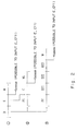
- the throwing-away method for asynchronous processing of the present invention will be described in comparison with the case where it is not used.
- the basic timing in a pipeline system in which the throwing-away method is not used is shown in Fig. 1, while the timing of the case where the throwing-away method is shown in Fig. 2.
- Each time interval has a duration of 1 ⁇ and is synchronous timing. Symbols are used to explain operations allotted to the time intervals and the meaning of each symbol is indicated below.
- D Decode: Decoding of an instruction and an execute initiation condition (a collision of a data-dependent relationship and a resource)
- E Execute: Execution of an arithmetic operation, computation of an execute address in the case of a main storage access instruction
- W Write: Writing of the result of execution
- P1 Priority of load: Enqueuing into asynchronous processing queue and detecting of an execute initiation condition (a collision of a data-dependent relationship and a resource)
- C Cache: Address translation and reading of data from a cache
- W1 Write of load: Writing of data read from the cache (and the main storage) into a register
- Pf Priority of floating point operation: Enqueuing into an asynchronous execution queue and detecting of an execute initiation condition (a collision of a data-dependent relationship and a resource)
- Ef1 Execut
- pipeline processing is performed in the order of D, E and W in inter-register arithmetic operation as shown in Fig. 1 1.
- the pipeline is permitted at the end of the E cycle.
- a C cycle for address translation and reading of data from the cache is needed. Bypassing is permitted at the end of this cycle.
- Fig. 2 shows the case where the throwing-away method is used as in the present invention. 1 is the same as the case where the throwing-away method is not used.
- a P1 interval is present at the end of the D cycle as shown in 2. That is, after enqueuing into an asynchronous queue and detecting of an execute initiation condition (a collision of a data-dependent relationship and a resource), the C cycle follows. These operations can be performed by the throwing-away method.
- enqueuing into the asynchronous queue and detecting of an execute initiation condition (a collision of a data-dependent relationship and a resource) are performed by the throwing-away method.
- a floating-point operation cycle follows. In the throwing-away method, parallel operations are performed such that asynchronization operation is thrown away from or independent from the synchronization operation. Detailed timing of synchronization and non-synchronization is indicated in Fig. 3.
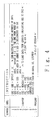
- FIG. 4 A timing diagram for a program for obtaining the sum of arrays using basic timing in the cases where the throwing-away method is used and it is not used will be described using an example of Fig. 4.
- the instruction numbers 1 to 10 of the program correspond to the numbers indicated on the left of the timing chart.
- Each of the instructions 1 to 4 is made possible by pipelining of synchronous processes D, E, W.
- the program enters looping and the cache is used at the first instruction within the loop, i.e., the fifth instruction.
- the basic cycle is formed of D, E, C, W.
- addition of floating-point arithmetic is performed and its operand is the result of execution of the fourth instruction and the result of execution of the fifth instruction. If there is a data-dependent relationship and data is not gathered, the floating-point addition cannot be performed.
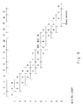
- the addition of GR 2 and 3 is performed in the instruction 7 which becomes D, D, Ef1, Ef2, Ef3, Wf after a delay of 1 ⁇ as shown in the number 6 of the timing chart of Fig. 5.
- the eighth Compare instruction and the ninth Branch instruction are performed in pipeline by D, E, W and, when a jump is made to the instruction 5 at the instruction 9, a delay of 1 ⁇ is produced as branch penalty to start D, E, W.
- the timing chart of this operation using the throwing-away method of the computer of the present invention is shown in Fig. 6.
- the numbers 1, 2, 3 are the same as those in Fig. 5.
- the cache operation is performed asynchronously as shown in 5-asynchronization and the P1, C, W1 cycles are performed such that they are asynchronous.
- the C cycle of 5-asynchronization overlaps W of 5 and they are performed simultaneously.
- the execution is faster than the case of Fig. 5.
- the floating-point arithmetic of the instruction 6 the execution is performed using the instructions 6 and 6-asynchronization and after decoding advance can be made to the 6-asynchronization state using the throwing-away method.
- the output of C of 5-asynchronization is used as the input of Ef1 of 6-asynchronization.
- its D cycle can be performed like the E cycle of the instruction 6, that is, the Pf cycle of 6-asynchronization.
- the instructions 8, 9, 10 are the same as those in the previous case.
- the resuming operation for asynchronous processing interruption of the present invention and the invention relating to data-dependent accounting are used in a computer using such a throwing-away method.
- the instruction format is as follows.
- OPC Instruction code. The position parts of other fields of an instruction may be ignored, depending on the value of the OPC. It is assumed that whether the instruction bits 17 to 31 indicate GR or FR is determined by the value of the OPC as follows.
- the instruction bits 17 to 31 indicate GR.
- the instruction bits 17 to 31 indicate FR.
- IMM Immediate data (input)
- GRN1 GR Number 1, input GR register number 1 GRN2: GR Number 2, input GR register number 2 GRN3: GR Number 3, output GR register number 3
- FRN1 FR Number 1, input FR register number 1 FRN2: FR Number 2, input FR register number 2 FRN3: FR Number 3, output FR register number
- Outputs of a CPU-resource-using-process-dependent interruption and a CPU-resource using process indicate values different from expected values.
- the low order seven bits of the IMM part of an SVC instruction + 0 x 80 are used as a call number.
- the external interruptions have levels 0 to 15. Only external interruption signals with levels above EAL of PSR are accepted to initiate interruption.
- This general purpose register is used as a base register or an index register for addressing destination of the input/output of an operation or a main storage.
- GR is 32 bits in length and 32 GRs are present. GR numbers 0 to 31 are uniquely allocated to the GRs. GR0 holds 0 at all times. The writing into the GR0 is ignored and a 0 is always read when the GR0 is read.
- An FR is 64 bits in length and 32 FRs are present. Unique FR numbers 0 to 31 are allocated to the FRs. The FR0 holds a 0 at all times. The writing into the FR0 is ignored. A 0 is always read when the FR0 is read.
- CR0 PSR (Processor Status Register) This register holds parameters (supervisor mode/user mode, etc.) for defining the main operating environment of a program.
- the PSR contains a CC (Condition Code: Condition Code Area) of 2 bits in length and an EAL (External Interrupt Accept Level) of 4 bits in length.
- the CC becomes a candidate for outputting in specific processing and is used as an input for branch determination in conditional branch processing.
- the EAL defines the level of an accepted external interruption factor. Only external interruption signals having a value larger than the EAL are accepted to initiate interruption operation.
- CRI OPSR (Old PSR) This is a register for holding the PSR value prior to the occurrence of an interruption at the time of the occurrence of the interruption.
- CR2 OIC (Old Instruction Counter) This is a register for holding the PC value (which points to the address of an instruction to be executed next) prior to the occurrence of an interruption at the time of the occurrence of the interruption.
- CR3 OLEP (Old Last Entry Pointer) This is a register for holding the last entry pointer value of a run queue of asynchronous processes after wait for the termination of the asynchronous processes.
- CR4 INTD (INTerrupt Designation) This is a register for holding a code (INTTYPE) indicating the type of an interruption at the occurrence of the interruption and a termination code (LSRETC) of an asynchronous process executed last at the occurrence of a program interruption in the form shown in Fig. 9.
- INTTYPE a code indicating the type of an interruption at the occurrence of the interruption
- LRETC termination code
- the following values are allocated to the INTTYPE.
- Each of the APCRs has the following form.
- instruction execution controller For the operation of the instruction execution controller, refer to /5/.
- the instruction execution controller includes the following registers.
- the SRETC (Synchronous process RETurn code) in the CR is set in accordance with the result of the execution of the process.
- the entries ranging from APQE1 to APQE(SEP - 1) are being executed.
- APQE(SEP) is an entry to be executed next.
- APQE(SEP + 1) to APQE(LEP) are entries which are initiated by instructions but are placed in the execution wait state.
- APQE(LEP + 1) indicates an entry to be enqueued next.
- register interference detection facility for the instruction buffer and an entry pointed to by a starting-point pointer.
- the CR number in the instruction buffer is 0 or the GR number in the entry pointed to by the starting-point pointer is 0, it is determined that the area is not included in an area for comparison.
- the facility for determining whether or not IB.GRN1 is included in the GRN3 area of APQE1 to APQE(LEP) The facility for determining whether or not IB.GRN2 is included in the GRN3 area of APQE1 to APQE(LEP)
- the instruction in IB specifies FR, the same determination facility as in the item 3.
- the facility for determining whether or not a process (OPC) for modifying CC is included in APQE1 to APQE(LEP) when IB.OPC is a process for modifying or referring to CC.
- IB.OPC is not a process for accessing CC, it is determined that there is no interference by CC.
- the data interference signal line to the instruction execution controller is a 1.
- the facility for determining whether or not SEB.GRN1 is included in the GRN3 area of APQE1 to APQE(LEP) The facility for determining whether or not SE.GRN2 is included in the GRN3 area of APQE1 to APQE(LEP)
- the instruction in SE specifies FR, the same determination facility as in the item 3.
- the facility for determining whether or not a process (OPC) for modifying CC is included in APQE1 to APQE(SEP-1) when SE OPC is a process for modifying CC.
- OPC process for modifying CC
- Enqueuing into and dequeuing from the asynchronous process queue are performed by an enqueue and dequeue controller as follows.
- the instruction execute controller When detecting that an instruction in the instruction buffer indicates asynchronous processing, the instruction execute controller issues a request for enqueuing of an asynchronous process to the enqueue and dequeue controller.
- the enqueue and dequeue controller adds 1 to the LEP and copies the contents of the instruction buffer into an entry pointed to by the new value of the LEP.
- the RETC and EXID of the entry is initialized to 0.
- the asynchronous process queue is full and a new entry cannot be enqueued. In this case, the execution of an instruction is delayed until an entry has been dequeued from the queue.
- the asynchronous process execute controller specifies EXID to prompt the enqueue dequeue controller to dequeue the entry.
- the enqueue dequeue controller shifts each of entries following the entry having the specified EXID to its previous entry and decrements each of the SEP and LEP by one.
- the enqueue dequeue controller is a unit which holds the starting entry pointer (SEP) and the last entry pointer (LEP) and perform the next operation.
- the asynchronous process execute controller performs the determination of initiation of the entry pointed to by the SEP, the control of execute initiation of transmission of the instruction code and EXID to the process execute unit and processing thereof and the control at the time of termination of an asynchronous process.
- the asynchronous process execute controller For the operation of the asynchronous process execute controller, refer to /5/.
- the asynchronous process execute controller includes the following two 31-bit length registers.
- the EXIDB#(X) indicates whether or not an asynchronous process having the X value as the EXID is used in the following manner. 0: The EXID of the X value is not used. 1: The X value is used as the EXID. An asynchronous process having the X value as the EXID is either being executed or has been terminated as a result of detection of a program interruption factor.
- the asynchronous process execute controller is responsive to reception of the following signal from the instruction execute controller to perform a specific operation when it is a 1.
- the asynchronous process execute controller Upon receipt of this signal, the asynchronous process execute controller performs the following operation at a specific time.
- the asynchronous process execute controller transmits the following two types of signals to the instruction execute controller.
- This signal becomes a 1 in the following condition.
- the LEP is a 0, or all the EXIDBs are not 0s and the EXIDBs are equal to the EXIDRs.
- the enqueue dequeue controller is prompted to enqueue a process in the instruction buffer and a determination is made as to whether or not the asynchronous process queue is one byte. If NO, 4 is added to the IC and then a return is made to the first.
- the enqueue dequeue controller is prompted to copy the asynchronous process queue into the asynchronous process queue copy register and initialize it.
- the enqueue dequeue controller copies APQE#1 to APQE#(LEP) into APCR#1 to APCE#(LEP).
- a 0 is set in the LEP and a 1 is set in the SEP.
- a 1 is output to the asynchronous process reset signal for a fixed period of time, during which period the asynchronous process execute controller sets the EXIDB and the EXIDR to 0.
- the SRECTC is copied into the LSRETC and 0 x 10 is set in the INTTYPE.
- a 1 is set to the EXIDB#X.
- X is added, as the EXID, to the contents of the entry pointed to by the SEP and transmitted to an asynchronous process execute unit which executes the process.
- the corresponding asynchronous process unit initiates the process.
- X is added to prompt the enqueue dequeue controller to modify the SEP. After setting X to the EXID of the entry pointed to by the SEP, the enqueue dequeue controller adds a 1 to the SEP.
- EXID and the RECT (termination code) of the execution terminate process that each asynchronous process execute unit transmits are accepted.
- the following processes are performed on accepted sets of EXID-X and RETC-Y.
- the enqueue dequeue controller is prompted to dequeue the entry having EXID-X.
- the enqueue dequeue controller shifts each of entries following the entry having EXID-X to the entry one entry before, The SEP and the LEP are decremented by one.
- a 0 is set to the EXIDB#(X).
- the enqueue dequeue controller is prompted to set RETC-Y to the RETC of the entry having EXID-X.
- the enqueue dequeue controller executes this process.
- a 1 is set to the EXIDR#(X).
- LEP is 0 (SEP is 1), PSR ⁇ OPSR, IC ⁇ OIC are set and the enqueue dequeue controller is prompted to transfer the contents of the asynchronous queue copy register to the asynchronous process queue. After copying the contents of APCR#1 to APCR#(OLEP) to APQE#1 to APQE#(OLEP), the enqueue dequeue controller sets LEP - OLEP. The end of [C] is reached and When LEP is not 0, it is handled as NOP.
- N3 area in IB For N3 area in IB, a comparison is made with all N1, N2 and N3 areas of each queue entry.
- the data-dependent relationship between entries pointed to by SBP(start entry pointer) may be detected by the following two methods.
- IB is replaced by APSB.
- LEP and its decoder are replaced by SEP and its decoder, respectively.
- An instruction that enters the instruction buffer is the newest one and its dependent relationship with instructions that entered in the past is examined.
- the OPC of the instruction buffer that is, the type of instruction is examined by decoding. Instructions are classifyed into instructions specifying GR and instructions specifying FR. N1, N2, N3 indicated in the instruction buffer correspond to N1, N2, N3 of GR or N1, N2, N3 of FR. They are made clear by decoding OPC.
- GR or FR is seen by the most significant bit of the OPC. It is GR when the most significant bit is 0, when it is FR when the most significant bit is 1.
- An decoded output for example, IB N1 GR by OPC, is a signal which becomes 1 when N1 is GR as a result of decoding of OPC.
- N2, N3 is a determination can be made as to whether each field of N1, N2, N3 is Gr or FR by decoding the OPC of an instruction in an asynchronous queue entry.
- QE# x N3 GR by OPC is a signal which goes to a 1 when the x-th asynchronous instruction in the asynchronous queue is N3 field GR and so on.
- the N1 field in the instruction buffer 1B is decoded and 1B N1 NOT 0 goes to a 1 when all 0s are not detected.
- the specified instruction makes no conflicts (data-dependent relationship) with the queued instruction.
- N1 is 0, there is no data-dependent relationship because the contents of GRO or FRO specified by N1 are zero-fixed.
- 1B N1 NOT 0 is 1, there is the possibility of conflicts.
- AND1 outputs a 1 when the N1 area is GR and the N1 area is not 0.
- AND5 outputs a 1 when the N3 area is GR and the N3 area is not 0.
- AND6 outputs a 1 when the N3 area is FR and the N3 area is not 0.
- each of the ANDs 5, 6 is supplied with AQE#X LEP valid, which is a signal which is obtained by decoding the last entry pointer LEP of the queue and goes to a 1 when an #X the entry whose asynchronization process is not yet executed is befores the last esntry or does not yet produce the resalt of the execution.
- the AND 3, 4 see whether N1 in the instruction buffer is GR, its contents are not 0, and the same GRN1 as it is the same GR indicated by N3 of queuing.
- N1 of OPC is GR and the GR has become N3 of a queued instruction, that is, whether N3 of the GR instruction buffer receiving the results of an asynchronous queue process is the same as N3 of the asynchronous queue.
- each of ANDs 5, 6 is supplied with AQE#X LEP valid, which is a signal which is obtained by decoding the last entry pointer of the queue and goes to a 1 when the #X-th entry whose asynchronous process has not been executed yet is before the last entry or has not yet produced the result of the execution.
- the AND 3, 4 see whether N1 in the instruction buffer is FR, its contents are not 0, and the same GRN1 as it is the same FR indicated by N3 of queuing.
- N1 of OPC is Gr and the GR has become N3 of a queued instruction, that is, whether N3 of the FR instruction buffer receiving the results of an asynchronous queue process is the same as N3 of the asynchronous queue.
- the number of the instruction buffer is one and the number of the asynchronous queues is 32, the number of the circuits which are the same as that of Fig. 14 is 32.
- Fig. 15 illustrates a second embodiment of the present invention which is distinct from the first embodiment shown in Fig. 7 in that, instead of using the asynchronous process queue copy register, an asynchronous process freeze signal is applied to the asynchronous process queue to fix the contents of the asynchronous process queue.
- the second embodiment is distinct from the first embodiment in that FEP, LEP, FXIDB, FXIDR are made accessible as CR and an asynchronous process reset signal 1 is used as the asynchronous process freeze signal 1.
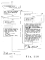
- Fig. 16 is a flowchart of the operation of the instruction execute controller in the second embodiment which corresponds to the flowchart of the first embodiment shown in Fig. 11B.
- SRETC 0 or whether the asynchronous process 51 program interruption signal is 1. If NO, a determination is made as to whether SVCC is 0.
- SVCC is copied into INTTYPE, a 0 is set to SVCC, and OPRS - PSR, PSR - NPSR are set. In this case, the EAL value remains unchanged.
- a 1 is set to PRS, FASP.
- the asynchronous process freeze signal is set to one and SRETC is copied into LSRETC.
- 0 x 10 is set in INTTYPE and OPSR ⁇ PSR, PSR ⁇ NPSR.
- the EAL value remains unchanged and, in the presence of an asynchronous process program interruption, one is set in PSR, FASP.
- SRETC is copied into LSRETC without making the asynchronous process freeze signal one.
- Fig. 17 illustrates a flowchart of the RTC instruction shown in [C] of Fig. 11A in accordance with the second embodiment, which corresponds to Fig. 13 of the first embodiment.
- an interruption handling system which can speed up asynchronous CPU resource using processes, execute basic CPU resource using processes used by an interruption handler asynchronously and produce the interruption handler easily. Further, asynchronous execution of basic asynchronous CPU resource using processes used by the interruption handler is possible and for a necessary CPU resource using process dependent factor, an interruption system for permitting an original program to be resumed becomes possible after termination of a corresponding process by the interruption handler.
Landscapes
- Engineering & Computer Science (AREA)
- Software Systems (AREA)
- Theoretical Computer Science (AREA)
- Physics & Mathematics (AREA)
- General Engineering & Computer Science (AREA)
- General Physics & Mathematics (AREA)
- Advance Control (AREA)
- Multi Processors (AREA)
- Bus Control (AREA)
Applications Claiming Priority (4)
| Application Number | Priority Date | Filing Date | Title |
|---|---|---|---|
| JP6915890 | 1990-03-19 | ||
| JP69158/90 | 1990-03-19 | ||
| JP6915890 | 1990-03-19 | ||
| PCT/JP1991/000370 WO1991014985A1 (en) | 1990-03-19 | 1991-03-19 | Interrupt processing system |
Publications (3)
| Publication Number | Publication Date |
|---|---|
| EP0482200A1 true EP0482200A1 (de) | 1992-04-29 |
| EP0482200A4 EP0482200A4 (en) | 1993-10-13 |
| EP0482200B1 EP0482200B1 (de) | 2001-09-19 |
Family
ID=13394606
Family Applications (1)
| Application Number | Title | Priority Date | Filing Date |
|---|---|---|---|
| EP91906311A Expired - Lifetime EP0482200B1 (de) | 1990-03-19 | 1991-03-19 | Unterbrechungsverarbeitungssystem |
Country Status (6)
| Country | Link |
|---|---|
| US (1) | US5301331A (de) |
| EP (1) | EP0482200B1 (de) |
| AU (1) | AU646247B2 (de) |
| CA (1) | CA2056356C (de) |
| DE (1) | DE69132733T2 (de) |
| WO (1) | WO1991014985A1 (de) |
Families Citing this family (15)
| Publication number | Priority date | Publication date | Assignee | Title |
|---|---|---|---|---|
| US5787303A (en) * | 1991-10-31 | 1998-07-28 | Kabushiki Kaisha Toshiba | Digital computer system capable of processing a plurality of instructions in parallel based on a VLIW architecture |
| JPH06161779A (ja) * | 1992-11-17 | 1994-06-10 | Fujitsu Ltd | データ処理装置の割込み制御方式 |
| JP3338488B2 (ja) * | 1992-11-18 | 2002-10-28 | 富士通株式会社 | データ処理装置の検証方法及び装置 |
| US5465336A (en) * | 1994-06-30 | 1995-11-07 | International Business Machines Corporation | Fetch and store buffer that enables out-of-order execution of memory instructions in a data processing system |
| WO1997009674A1 (fr) * | 1995-09-01 | 1997-03-13 | Hitachi, Ltd. | Processeur de donnees |
| US5900024A (en) * | 1996-11-07 | 1999-05-04 | Oracle Corporation | Method for processing type-ahead input and operation-abort input |
| US6199143B1 (en) * | 1997-11-26 | 2001-03-06 | International Business Machines Corporation | Computing system with fast data transfer of CPU state related information |
| US6721696B1 (en) | 2000-02-25 | 2004-04-13 | Centric Software, Inc. | Simulation program having generic attribute access schema |
| US6944583B1 (en) * | 2000-02-02 | 2005-09-13 | Centric Software, Inc. | Multi-threaded frame safe synchronization of a simulation |
| US7373504B1 (en) * | 2004-03-18 | 2008-05-13 | Sun Microsystems, Inc. | Kernel-level cryptographic kernel interface |
| US9384159B2 (en) * | 2007-05-24 | 2016-07-05 | International Business Machines Corporation | Creating a checkpoint for a software partition in an asynchronous input/output environment |
| US20100191708A1 (en) * | 2009-01-23 | 2010-07-29 | International Business Machines Corporation | Synchronous Deletion of Managed Files |
| US8296411B2 (en) * | 2010-03-01 | 2012-10-23 | International Business Machines Corporation | Programmatically determining an execution mode for a request dispatch utilizing historic metrics |
| US8549506B2 (en) | 2010-04-27 | 2013-10-01 | Microsoft Corporation | Resumable methods |
| JP5699554B2 (ja) | 2010-11-11 | 2015-04-15 | 富士通株式会社 | ベクトル処理回路、命令発行制御方法、及びプロセッサシステム |
Family Cites Families (15)
| Publication number | Priority date | Publication date | Assignee | Title |
|---|---|---|---|---|
| JPS54107645A (en) * | 1978-02-13 | 1979-08-23 | Hitachi Ltd | Information processor |
| JPS6043535B2 (ja) * | 1979-12-29 | 1985-09-28 | 富士通株式会社 | 情報処理装置 |
| US4423480A (en) * | 1981-03-06 | 1983-12-27 | International Business Machines Corporation | Buffered peripheral system with priority queue and preparation for signal transfer in overlapped operations |
| US4456970A (en) * | 1981-12-10 | 1984-06-26 | Burroughs Corporation | Interrupt system for peripheral controller |
| US4758950A (en) * | 1983-04-18 | 1988-07-19 | Motorola, Inc. | Method and apparatus for selectively delaying an interrupt of a coprocessor |
| US4739472A (en) * | 1984-12-07 | 1988-04-19 | Nec Corporation | Information processing device capable of rapidly processing instructions of different groups |
| JPS61285541A (ja) * | 1985-06-13 | 1986-12-16 | Nec Corp | 情報処理装置 |
| US4716523A (en) * | 1985-06-14 | 1987-12-29 | International Business Machines Corporation | Multiple port integrated DMA and interrupt controller and arbitrator |
| JPS61288226A (ja) * | 1985-06-17 | 1986-12-18 | Panafacom Ltd | 外部コンデイシヨン制御方式 |
| US4761732A (en) * | 1985-11-29 | 1988-08-02 | American Telephone And Telegraph Company, At&T Bell Laboratories | Interrupt controller arrangement for mutually exclusive interrupt signals in data processing systems |
| US4959782A (en) * | 1986-10-29 | 1990-09-25 | United Technologies Corporation | Access arbitration for an input-output controller |
| JPS648446A (en) * | 1987-06-30 | 1989-01-12 | Nec Corp | Information processor |
| JP2532560B2 (ja) * | 1988-03-09 | 1996-09-11 | 三菱電機株式会社 | 高機能な例外処理を行うデ―タ処理装置 |
| US4897810A (en) * | 1988-06-13 | 1990-01-30 | Advanced Micro Devices, Inc. | Asynchronous interrupt status bit circuit |
| US5155809A (en) * | 1989-05-17 | 1992-10-13 | International Business Machines Corp. | Uncoupling a central processing unit from its associated hardware for interaction with data handling apparatus alien to the operating system controlling said unit and hardware |
-
1991
- 1991-03-19 AU AU74803/91A patent/AU646247B2/en not_active Ceased
- 1991-03-19 DE DE69132733T patent/DE69132733T2/de not_active Expired - Fee Related
- 1991-03-19 EP EP91906311A patent/EP0482200B1/de not_active Expired - Lifetime
- 1991-03-19 US US07/776,347 patent/US5301331A/en not_active Expired - Lifetime
- 1991-03-19 WO PCT/JP1991/000370 patent/WO1991014985A1/ja not_active Ceased
- 1991-03-19 CA CA002056356A patent/CA2056356C/en not_active Expired - Fee Related
Also Published As
| Publication number | Publication date |
|---|---|
| CA2056356A1 (en) | 1991-09-20 |
| AU646247B2 (en) | 1994-02-17 |
| DE69132733T2 (de) | 2002-05-29 |
| AU7480391A (en) | 1991-10-21 |
| US5301331A (en) | 1994-04-05 |
| DE69132733D1 (de) | 2001-10-25 |
| EP0482200B1 (de) | 2001-09-19 |
| CA2056356C (en) | 1998-06-09 |
| WO1991014985A1 (en) | 1991-10-03 |
| EP0482200A4 (en) | 1993-10-13 |
Similar Documents
| Publication | Publication Date | Title |
|---|---|---|
| US7020871B2 (en) | Breakpoint method for parallel hardware threads in multithreaded processor | |
| US5809268A (en) | Method and system for tracking resource allocation within a processor | |
| US5341482A (en) | Method for synchronization of arithmetic exceptions in central processing units having pipelined execution units simultaneously executing instructions | |
| US5519864A (en) | Method and apparatus for scheduling the dispatch of instructions from a reservation station | |
| US5075840A (en) | Tightly coupled multiprocessor instruction synchronization | |
| US6237089B1 (en) | Method and apparatus for affecting subsequent instruction processing in a data processor | |
| US5450560A (en) | Pointer for use with a buffer and method of operation | |
| US5694565A (en) | Method and device for early deallocation of resources during load/store multiple operations to allow simultaneous dispatch/execution of subsequent instructions | |
| EP0482200B1 (de) | Unterbrechungsverarbeitungssystem | |
| US5604878A (en) | Method and apparatus for avoiding writeback conflicts between execution units sharing a common writeback path | |
| US20060218124A1 (en) | Performance of a data processing apparatus | |
| US6393550B1 (en) | Method and apparatus for pipeline streamlining where resources are immediate or certainly retired | |
| US5898864A (en) | Method and system for executing a context-altering instruction without performing a context-synchronization operation within high-performance processors | |
| US5619730A (en) | Pipelining device in a parallel processing apparatus and an instruction supplying method therefor | |
| US5996059A (en) | System for monitoring an execution pipeline utilizing an address pipeline in parallel with the execution pipeline | |
| US6324640B1 (en) | System and method for dispatching groups of instructions using pipelined register renaming | |
| JP3207124B2 (ja) | カウント/リンク・レジスタ変更命令の投機実行をサポートする方法及び装置 | |
| US5522084A (en) | Method and system for invalidating instructions utilizing validity and write delay flags in parallel processing apparatus | |
| KR100310798B1 (ko) | 머신문맥동기화동작실행방법및프로세서 | |
| US7302553B2 (en) | Apparatus, system and method for quickly determining an oldest instruction in a non-moving instruction queue | |
| RU2150738C1 (ru) | Система обработки и способ ее функционирования | |
| US5742755A (en) | Error-handling circuit and method for memory address alignment double fault | |
| US5850563A (en) | Processor and method for out-of-order completion of floating-point operations during load/store multiple operations | |
| JPH10275078A (ja) | 命令をディスパッチする方法及びシステム | |
| IE62074B1 (en) | Apparatus and method for synchronization of arithmetic exceptions in parallel pipelined execution units |
Legal Events
| Date | Code | Title | Description |
|---|---|---|---|
| PUAI | Public reference made under article 153(3) epc to a published international application that has entered the european phase |
Free format text: ORIGINAL CODE: 0009012 |
|
| 17P | Request for examination filed |
Effective date: 19911209 |
|
| AK | Designated contracting states |
Kind code of ref document: A1 Designated state(s): DE ES FR GB |
|
| A4 | Supplementary search report drawn up and despatched |
Effective date: 19930826 |
|
| AK | Designated contracting states |
Kind code of ref document: A4 Designated state(s): DE ES FR GB |
|
| 17Q | First examination report despatched |
Effective date: 19970630 |
|
| GRAG | Despatch of communication of intention to grant |
Free format text: ORIGINAL CODE: EPIDOS AGRA |
|
| GRAG | Despatch of communication of intention to grant |
Free format text: ORIGINAL CODE: EPIDOS AGRA |
|
| GRAH | Despatch of communication of intention to grant a patent |
Free format text: ORIGINAL CODE: EPIDOS IGRA |
|
| GRAH | Despatch of communication of intention to grant a patent |
Free format text: ORIGINAL CODE: EPIDOS IGRA |
|
| GRAA | (expected) grant |
Free format text: ORIGINAL CODE: 0009210 |
|
| AK | Designated contracting states |
Kind code of ref document: B1 Designated state(s): DE ES FR GB |
|
| PG25 | Lapsed in a contracting state [announced via postgrant information from national office to epo] |
Ref country code: FR Free format text: LAPSE BECAUSE OF FAILURE TO SUBMIT A TRANSLATION OF THE DESCRIPTION OR TO PAY THE FEE WITHIN THE PRESCRIBED TIME-LIMIT Effective date: 20010919 |
|
| REF | Corresponds to: |
Ref document number: 69132733 Country of ref document: DE Date of ref document: 20011025 |
|
| REG | Reference to a national code |
Ref country code: GB Ref legal event code: IF02 |
|
| PG25 | Lapsed in a contracting state [announced via postgrant information from national office to epo] |
Ref country code: ES Free format text: LAPSE BECAUSE OF FAILURE TO SUBMIT A TRANSLATION OF THE DESCRIPTION OR TO PAY THE FEE WITHIN THE PRESCRIBED TIME-LIMIT Effective date: 20020326 |
|
| EN | Fr: translation not filed | ||
| PLBE | No opposition filed within time limit |
Free format text: ORIGINAL CODE: 0009261 |
|
| STAA | Information on the status of an ep patent application or granted ep patent |
Free format text: STATUS: NO OPPOSITION FILED WITHIN TIME LIMIT |
|
| 26N | No opposition filed | ||
| PGFP | Annual fee paid to national office [announced via postgrant information from national office to epo] |
Ref country code: GB Payment date: 20060315 Year of fee payment: 16 |
|
| PGFP | Annual fee paid to national office [announced via postgrant information from national office to epo] |
Ref country code: DE Payment date: 20060316 Year of fee payment: 16 |
|
| GBPC | Gb: european patent ceased through non-payment of renewal fee |
Effective date: 20070319 |
|
| PG25 | Lapsed in a contracting state [announced via postgrant information from national office to epo] |
Ref country code: DE Free format text: LAPSE BECAUSE OF NON-PAYMENT OF DUE FEES Effective date: 20071002 |
|
| PG25 | Lapsed in a contracting state [announced via postgrant information from national office to epo] |
Ref country code: GB Free format text: LAPSE BECAUSE OF NON-PAYMENT OF DUE FEES Effective date: 20070319 |