EP0482250B1 - Luftgeschwindigkeitsregelsystem für Flugzeugvortriebsregler - Google Patents
Luftgeschwindigkeitsregelsystem für Flugzeugvortriebsregler Download PDFInfo
- Publication number
- EP0482250B1 EP0482250B1 EP90202852A EP90202852A EP0482250B1 EP 0482250 B1 EP0482250 B1 EP 0482250B1 EP 90202852 A EP90202852 A EP 90202852A EP 90202852 A EP90202852 A EP 90202852A EP 0482250 B1 EP0482250 B1 EP 0482250B1
- Authority
- EP
- European Patent Office
- Prior art keywords
- airspeed
- change
- airplane
- value
- thrust
- Prior art date
- Legal status (The legal status is an assumption and is not a legal conclusion. Google has not performed a legal analysis and makes no representation as to the accuracy of the status listed.)
- Expired - Lifetime
Links
- 230000008859 change Effects 0.000 claims description 117
- 238000009499 grossing Methods 0.000 claims description 4
- 230000004048 modification Effects 0.000 claims 4
- 238000012986 modification Methods 0.000 claims 4
- 238000001914 filtration Methods 0.000 claims 1
- 230000000694 effects Effects 0.000 description 15
- 238000010586 diagram Methods 0.000 description 10
- 239000000446 fuel Substances 0.000 description 8
- 230000032683 aging Effects 0.000 description 4
- 230000009194 climbing Effects 0.000 description 4
- 230000007704 transition Effects 0.000 description 4
- 230000001133 acceleration Effects 0.000 description 2
- 230000009471 action Effects 0.000 description 2
- 238000004364 calculation method Methods 0.000 description 2
- 230000009467 reduction Effects 0.000 description 2
- 206010037180 Psychiatric symptoms Diseases 0.000 description 1
- 239000000654 additive Substances 0.000 description 1
- 230000000996 additive effect Effects 0.000 description 1
- 230000001351 cycling effect Effects 0.000 description 1
- 238000004519 manufacturing process Methods 0.000 description 1
- 230000004044 response Effects 0.000 description 1
- 230000000630 rising effect Effects 0.000 description 1
- 239000004065 semiconductor Substances 0.000 description 1
Images


Classifications
-
- G—PHYSICS
- G05—CONTROLLING; REGULATING
- G05D—SYSTEMS FOR CONTROLLING OR REGULATING NON-ELECTRIC VARIABLES
- G05D1/00—Control of position, course, altitude or attitude of land, water, air or space vehicles, e.g. using automatic pilots
- G05D1/04—Control of altitude or depth
- G05D1/06—Rate of change of altitude or depth
- G05D1/0607—Rate of change of altitude or depth specially adapted for aircraft
- G05D1/0615—Rate of change of altitude or depth specially adapted for aircraft to counteract a perturbation, e.g. gust of wind
- G05D1/063—Rate of change of altitude or depth specially adapted for aircraft to counteract a perturbation, e.g. gust of wind by acting on the motors
-
- F—MECHANICAL ENGINEERING; LIGHTING; HEATING; WEAPONS; BLASTING
- F05—INDEXING SCHEMES RELATING TO ENGINES OR PUMPS IN VARIOUS SUBCLASSES OF CLASSES F01-F04
- F05B—INDEXING SCHEME RELATING TO WIND, SPRING, WEIGHT, INERTIA OR LIKE MOTORS, TO MACHINES OR ENGINES FOR LIQUIDS COVERED BY SUBCLASSES F03B, F03D AND F03G
- F05B2200/00—Mathematical features
- F05B2200/10—Basic functions
- F05B2200/11—Sum
-
- F—MECHANICAL ENGINEERING; LIGHTING; HEATING; WEAPONS; BLASTING
- F05—INDEXING SCHEMES RELATING TO ENGINES OR PUMPS IN VARIOUS SUBCLASSES OF CLASSES F01-F04
- F05B—INDEXING SCHEME RELATING TO WIND, SPRING, WEIGHT, INERTIA OR LIKE MOTORS, TO MACHINES OR ENGINES FOR LIQUIDS COVERED BY SUBCLASSES F03B, F03D AND F03G
- F05B2200/00—Mathematical features
- F05B2200/10—Basic functions
- F05B2200/13—Product
-
- F—MECHANICAL ENGINEERING; LIGHTING; HEATING; WEAPONS; BLASTING
- F05—INDEXING SCHEMES RELATING TO ENGINES OR PUMPS IN VARIOUS SUBCLASSES OF CLASSES F01-F04
- F05B—INDEXING SCHEME RELATING TO WIND, SPRING, WEIGHT, INERTIA OR LIKE MOTORS, TO MACHINES OR ENGINES FOR LIQUIDS COVERED BY SUBCLASSES F03B, F03D AND F03G
- F05B2200/00—Mathematical features
- F05B2200/20—Special functions
- F05B2200/21—Root
- F05B2200/211—Square root
Definitions
- This invention relates to airplane control systems and, more particularly, airspeed control systems for autothrottles.
- Autothrottles automatic throttle systems
- Fuel consumption is minimized and pilot confidence and acceptance of autothrottles is increased by autothrottles that control airplane cruise airspeed with minimum throttle activity (i.e., minimum throttle change). More specifically, accurate control of airplane airspeed is important because excess airspeed increases fuel consumption and lower than necessary airspeed increases flight time and other costs.
- Excessive throttle activity, overshoots, or throttle hunting also increase fuel consumption.
- Excessive throttle activity, overshoots, or throttle hunting also cause pilots to lose confidence in autothrottles. Loss of confidence may lead a pilot to disconnect an autothrottle system and control airspeed manually. Manual control often leads to worse airspeed control and additional fuel consumption because it is difficult for a pilot to continuously monitor airspeed and the airspeed excursions that result from throttle changes and wind changes.
- a fuel control system for a Gas Turbine Engine adjusting the fuel flow to the engine to produce a desired thrust means are provided to approximate the trim which will be required when the steady state is reached. This is applied throughout transients so that when the desired thrust is achieved only second-order changes need to be made.
- the present invention is directed to providing an automatic airspeed control system for an autothrottle that avoids the foregoing and other disadvantages. More specifically, the present invention is directed to providing an automatic airspeed control system for an autothrottle that controls airplane cruise speed more accurately and with less throttle activity than prior art airspeed control systems used in autothrottles. As a result, fuel consumption is reduced and pilot confidence and acceptance are increased.
- an automatic airspeed control system for an airplane autothrottle that provides rapid, accurate thrust settings when an airplane is rising to (i.e., acquiring) a new altitude, making a turn, encountering winds and changing airspeeds with a minimum of lag and error is provided.
- a predicted current thrust value is summed with a fine tune value, which is based on airspeed error, and the result is used to control airplane engine thrust via a closed loop control system.
- the predicted thrust value is created by summing the predicted airplane current steady state thrust value created, in a conventional manner, by the autothrottle of the airplane with a prediction correction value that compensates for airplane-to-airplane differences and changes that occur due to airplane aging.
- the thusly corrected predicted steady state thrust value is summed with an altitude acquire change thrust value and an airspeed change thrust value.
- the altitude acquire change thrust value is produced when an altitude change has been commanded by the autopilot.
- the airspeed change thrust value is produced when an airspeed change has been commanded by the autopilot system of the airplane, or wind or some other factor causes a non-autopilot commanded airspeed change.
- the airspeed change may be due to an autopilot commanded maneuver, e.g., a turn. More specifically, the commanded and wind airspeed change increment thrust values are based on the difference or error between the target airspeed set by the autopilot of the airplane and the actual airspeed of the airplane. An airspeed change increment thrust value is produced and automatically summed with the corrected predicted steady state thrust value when the autopilot commands an airspeed change. The wind change increment thrust value is produced and automatically summed with the corrected predicted steady state thrust value when an error exists between the autopilot commanded airspeed and the actual airspeed of the airplane, and the autopilot has not commanded an airspeed change.
- the altitude acquire change thrust value is based on the difference between the climb thrust and the cruise thrust of the airplane multiplied by an altitude acquire factor, preferably determined by taking the square root of the difference between the current altitude and the altitude to be acquired ( ⁇ h) divided by the difference between the starting altitude and the altitude to be acquired (d).
- the altitude acquire thrust change value is produced and automatically summed with the corrected predicted steady state thrust value when an altitude capture is commanded by the autopilot of the airplane.
- the fine tune value is obtained from a control loop that filters, integrates and applies a variable gain to airspeed errors.
- the variable gain is low when airspeed error is small and increases to a maximum for larger airspeed errors.
- control loop includes two paths, both of which include a variable gain.
- one path includes a second order filter and the other includes an integrator.
- Both paths receive an airspeed error value, i.e., a value that defines the difference between the target airspeed selected by the autopilot of the airplane and the actual airspeed of the airplane. The outputs of the two channels are summed and the result forms the fine tune value.
- the invention provides an automatic airspeed control system for an autothrottle that controls airplane cruise airspeed more accurately and with less throttle activity than prior art systems. Because airspeed is controlled more accurately and with less throttle activity, fuel consumption is reduced. Further, pilot confidence and acceptance of the autothrottle is increased.
- Minimal overshoot and hunting during climb results from the way the altitude acquisition change thrust value is generated, i.e., by multiplying the difference between climb and cruise thrust by a smoothing factor, preferably the square root of the difference between the current altitude during the climb and the altitude to be acquired ( ⁇ h) divided by the difference between the starting or original altitude and the altitude to be acquired (d).
- a fine tune variable gain control loop creates minimal throttle activity when airspeed errors are small and increased throttle activity when airspeed errors are high.
- FIGURE 1 illustrates an automatic airspeed control system for an airplane autothrottle formed in accordance with the invention.
- the airspeed control system provides rapid, accurate thrust settings when an airplane is climbing, making a turn, encountering winds and changing airspeed with a minimum of lag and error.
- a predicted steady state thrust value generated, in a conventional manner, by the autothrottle of the airplane is additively summed in a first summer 21 with a prediction correction value.
- the prediction correction value compensates for airplane-to-airplane differences and changes that occur due to airplane aging. That is, the prediction correction value compensates for small differences between airplanes, engines and sensors, resulting from manufacturing differences and changes that occur with airplane aging.
- the prediction correction value also compensates for minor prediction algorithm errors, i.e., minor errors in the autothrottle algorithm used to create the predicted steady state thrust value.
- the prediction correction value is built up slowly over time. The presently preferred way of generating the prediction correction value is illustrated in FIGURE 2 and described next.
- the presently preferred way of generating the prediction correction value is to subtractively combine the actual thrust of the aircraft derived from the engine control servo loop, in the manner illustrated in FIGURE 1 and described below, with the predicted steady state thrust value generated by the autothrottle in a second summer 23.
- the error between these values i.e., the output of the second summer 23, is applied through a first switch 25 to the input of a long-time constant integrator 27.
- a suitable integrator time constant value is .0001, resulting in the integrator being definable by the Laplace transform .0001/S.
- the switch 25 is only closed when the aircraft is in an altitude hold state and the airspeed error, i.c., the error between the actual airspeed of the airplane and the autopilot commanded target airspeed is relatively low--5,55 km [3 knots], for example.
- the prediction correction value is slowly built up over time. In effect, the prediction correction value compensates for thrust errors, i.e., the error between actual steady state thrust and predicted steady state thrust, during cruise. Because the prediction correction value corrects for airplane-to-airplane differences and airplane aging, the output of the first summer 21 of FIGURE 1 is a corrected predicted steady state thrust value. Because steady state only occurs at cruise, the output of the first summer can also be defined as a corrected predicted cruise thrust value.
- the output of the first summer 21 is additively summed with an altitude acquire change thrust value ( ⁇ T) in a third summer 29.
- the altitude acquire change thrust value ( ⁇ T) is applied to the third summer via a second switch 31.
- the altitude acquire change thrust value, ⁇ T is based on the difference between the climb thrust necessary to achieve a desired cruise altitude and the thrust required to maintain the cruise altitude after it is acquired.
- the second switch 31 is closed during the period of time the airplane is climbing from its original or starting altitude to the cruise altitude to be acquired.
- FIGURE 3 is a block diagram illustrating, in mathematical form, the presently preferred way of producing the altitude acquire change thrust value, ⁇ T.
- a fourth summer 33 subtractively sums the starting or reference altitude with the cruise altitude to be acquired. The result of the subtractive summation is a difference altitude designated d.
- a fifth summer 35 subtractively sums the cruise altitude to be acquired with the current altitude of the airplane, which continuously changes as the airplane climbs. The result of this subtractive summation is a difference altitude designated ⁇ h.
- ⁇ T is equal to the square root of ⁇ h divided by d times the difference between the airplane's climb thrust and the airplane's cruise thrust.
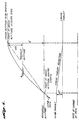
- FIGURE 4 illustrates that, in accordance with the invention, the difference between climb and cruise thrust is modified to linearly match the rate of change of the Dath.
- the thrust reduction from climb to cruise thrust is accomplished bv adding the difference between climb thrust and cruise thrust, multiplied by ⁇ h d , to the predicted cruise thrust to provide the linear thrust reduction required for an altitude acquire maneuver.
- the square root of the altitude error factor, ⁇ h d proportionally ramps the altitude acquire change thrust value, ⁇ T, such that a smooth linear transition occurs between climb and cruise thrust.
- the output of the third summer 29 is additively summed in a sixth summer 39 with an airspeed change thrust increment value.
- An airspeed change thrust increment value is produced in either of two ways. First, it is produced when the autopilot of the aircraft commands a change in airspeed. Second, it is produced when an error exists between the autopilot commanded airspeed and the actual airspeed of the aircraft, but the autopilot has not commanded an airspeed change. Airspeed errors in the absence of an airspeed change command most commonly occur when wind velocity changes. Hence, for purposes of this application, non-autopilot commanded airspeed changes are generically denoted wind airspeed changes, it being understood that factors other than wind can create a non-autopilot commanded airspeed change.
- FIGURES 5 and 6 are a block diagram illustrating, in control system form, the presently preferred way of producing an airspeed change thrust increment value.
- FIGURE 5 illustrates a control system that generates switch control signals that control switches illustrated in FIGURE 6.
- FIGURE 6 illustrates a control system for producing an airspeed change thrust increment value based on the setting of the switches.
- a target airspeed signal i.e., a signal denoting the airspeed commanded by the autopilot of the aircraft
- the seventh and eighth summers are both subtractive summers.
- the output of the seventh summer 41 is applied to the input of an integrator 45 and to the input of a limiter 47.
- the output of the limiter 47 is applied to the SET input of a latch 49.
- the output of the integrator 45 is applied to the negative input of the seventh summer 41.
- the integrator 45 is a time constant of .25 whereby the Laplace transform of the integrator is .25/s.
- the limiter 47 prevents the application of signals to the SET input of the latch 49 whose magnitude lie below a predetermined value, such as ⁇ 7,4 km [ ⁇ 4 knots], for example.
- a signal denoting the actual airspeed of the aircraft is applied to the positive input of the eighth summer 43.
- the output of the eighth summer 43 is applied to the inputs of first, second, third, and fourth hysteresis circuits 51, 52, 53, and 54, and to the input of a polarity detector 55.
- the hysteresis circuits produce binary one outputs when their inputs rise above a predetermined high value and binary zero outputs when their inputs drop below a predetermined low value.
- a suitable high value is ⁇ 9,26 km [ ⁇ 5 knots] and a suitable low value is ⁇ 3,7 km [ ⁇ 2 knots].
- a suitable high value is ⁇ 37 km [ ⁇ 20 knots] and a suitable low value is ⁇ 23,15 km [ ⁇ 12.5 knots].
- a suitable high value is ⁇ 5,55 km [ ⁇ 3 knots] and a suitable low value is ⁇ 2,78 km [ ⁇ 1.5 knots].
- a suitable high value is ⁇ 11,11 km [ ⁇ 6 knots] and a suitable low value is ⁇ 7,4 km [ ⁇ 4 knots].
- the output of the first hysteresis circuit 51 is applied to one input of a first two input AND gate 57.
- the output of the second hysteresis circuit 52 is applied to one input of a second two input AND gate 59.
- the Q output of the latch 49 is applied to the second inputs of the first and second AND gates 57 and 59.
- the output of the first AND gate 57 is a signal denoted SPEED CHANGE 1.
- the output of the first AND gate 57 is applied to the RESET input of the latch 49.
- the latch is reset on a binary one-to-zero transition.
- the output of the second AND gate 59 is a signal designated SPEED CHANGE 2.
- the binary state of the SPEED CHANGE 2 signal controls the state of another switch illustrated in FIGURE 6 and described below.
- the output of the third hysteresis circuit 53 is a signal designated OFFSPEED 1 and the output of the fourth hysteresis circuit is a signal designated OFFSPEED 2.
- the binary states of OFFSPEED 1 and OFFSPEED 2 control the states of a pair of switches illustrated in FIGURE 6 and described below.
- the output of the polarity detector is a signal designated OFFDEC.
- the binary state of the OFFDEC signal controls the state of a further switch illustrated in FIGURE 6 and described below.
- the seventh summer 41 in combination with the integrator 45 form a washout circuit that washes out slow changes in the target airspeed signal, i.e., prevents slow changes in the target airspeed signal from setting the latch 49. More specifically, as long as target airspeed signal changes are slow enough to allow the output of the integrator to counteract, i.e., wash out, the changing signal before the output rises to a level adequate to trigger the limiter 47, i.e., rises above or drops below ⁇ 7,4 km [ ⁇ 4 knots], the latch 49 is not set.
- the latch 49 is not set because the output of the limiter remains low as long as the signal input to the limiter lies between ⁇ 7,4 km [ ⁇ 4 knots]. If the limiter input rises above +7,4 km [+4 knots] or drops below -7,4 km [-4 knots], the output of the limiter shifts from a low, i.e., binary zero, state to a high, i.e., binary one, state. The shift from a low state to a high state sets the latch 49. Thus, only rapid changes in the target airspeed signal that cause the output of the seventh summer 41 to exceed ⁇ 7,4 km [ ⁇ 4 knots] causes the output of the limiter 47 to shift from a low state to a high state and the latch 49 to be set. When the latch 49 is set, its Q output goes high, whereby the first and second AND gates 57 and 59 are enabled to pass the outputs of the first and second hysteresis circuits 51 and 53.
- the output of the first hysteresis circuit 51 shifts from a low, i.e., binary zero, state to a high, i.e., binary one, state.
- a low i.e., binary zero
- a high i.e., binary one
- SPEED CIIANGE 1 signal shifting from a binary zero state to a binary one state, provided, of course, that the airspeed change was commanded by the autopilot and was rapid enough to set the latch 49 and enable the first AND gate 57 in the manner heretofore described.
- the output of the first hysteresis circuit 51 shifts from a binary one state to a binary zero state, resulting in the SPEED CHANGE 1 signal shifting from a binary one state to a binary zero state.
- This change resets the latch 49 and returns a switch illustrated in FIGURE 6 and described below to its quiescent state.
- the output of the second hysteresis circuit 52 shifts from a binary zero state to a binary one state.
- the SPEED CHANGE 2 signal shifts from a binary zero state to a binary one state, assuming again that the airspeed change was commanded by the autopilot and was rapid enough to set the latch 49.
- the output of the second hysteresis circuit 52 returns to a binary zero state, whereby the SPEED CIIANGE 2 signal shifts from a binary one state to a binary zero state.
- the state of SPEED CHANGE 2 controls the state of a switch.
- the output of the third hysteresis circuit shifts from a binary zero state to a binary one state.
- the OFFSPEED 1 signal shifts from a binary zero state to a binary one state.
- the output of the third hysteresis circuit and, thus, OFFSPEED 1 returns to a binary zero state.
- the output of the fourth hysteresis circuit shifts from a binary zero state to a binary one state.
- the OFFSPEED 2 signal shifts from a binary zero state to a binary one state.
- the airspeed error thereafter drops below ⁇ 7,4 km [ ⁇ 4 knots] the output of the fourth hysteresis circuit and, thus, OFFSPEED 2, returns to a binary zero state.
- the outputs of the first, second, third, and fourth hysteresis circuits overlap.
- a rapid change in autothrottle speed setting creating a greater than 37 km [20-knot] airspeed error will cause both SPEED CHANGE and both OFFSPEED signals to shift from binary zero states to binary one states.
- Rapid autothrottle changes creating a less than 37 km [20-knot] but greater than 9,26 km [5-knot] airspeed error will cause the SPEED CHANGE 1 and both OFFSPEED signals to shift from binary zero states to binary one states.
- Both rapid and slow speed changes creating an airspeed error greater than 11,11 km [6 knots] will cause both OFFSPEED signals to shift from binary zero states to binary one states, regardless of whether either or both of the SPEED CIIANGE signals change states.
- Both rapid and slow speed changes creating an airspeed error greater than 5,55 km [3 knots] but less than 11,11 km [6 knots] will cause the OFFSPEED 1 signal but not the OFFSPEED 2 signal to shift from a binary zero state to a binary one state regardless of whether both of the SPEED CHANGE signals change state.
- SPEED CHANGE 2 controls if the latch 49 is set and the magnitude of the airspeed error is greater than ⁇ 37 km [ ⁇ 20 knots]
- SPEED CHANGE 1 controls if the latch is set and the airspeed error is greater than ⁇ 9,26 km [ ⁇ 5 knots], but less than ⁇ 37 km [ ⁇ 20 knots].
- OFFSPEED 2 controls if the latch 49 is not set and the airspeed error is greater than ⁇ 11,11 km [ ⁇ 6 knots].
- OFFSPEED 1 controls if the latch is not set and the airspeed error is greater than ⁇ 5,55 km [ ⁇ 3 knots], but less than ⁇ 11,11 km [ ⁇ 6 knots].
- the polarity detector 55 responds to the polarity of the speed error signal. When the actual speed of the aircraft is less than the target airspeed, the output of the polarity detector is in a binary one state. When the actual airspeed of the aircraft is above the target airspeed, the output of the polarity detector 55 is in a binary zero state.
- a normalized, fixed thrust value is additively summed with an altitude correction factor by a ninth summer 61. More specifically, a signal representing a specific thrust value, such as 4,53,6 kg [1,000 pounds], normalized for a specific altitude, i.e., sea level, is applied to one input of the ninth summer 61.
- An altitude signal generated by the altimeter of the aircraft controls the magnitude of an altitude correction factor, which is applied to the second input of the ninth summer 61.
- the altitude correction is, thus, based on the altitude of the aircraft.
- the correction factor may, for example, be equal to .0004 for each 30,48 cm [foot] above sea level.
- the output of the ninth summer 61 is applied to the inputs of four multiplier circuits 63, 65, 67 and 69.
- the first and second multiplier 63 and 65 are associated with two switches whose states are controlled by the states of the OFFSPEED 1 and OFFSPEED 2 signals.
- the third and fourth multipliers 67 and 69 are associated with two switches whose states are controlled by the states of the SPEED CHANGE 1 and SPEED CHANGE 2 signals.
- all of these switches are schematically shown as single-poled double throw switches. In an actual embodiment of the invention, the switches would be either software switches or semiconductor switches controlled by binary zero and one voltages.
- the common terminal of the related switch When the controlling signal is in a binary zero state, the common terminal of the related switch is connected to the upper remote terminal of the switch. When the controlling signal is in a binary one state, the common terminal of the related switch is connected to the lower remote terminal of the switch. While different values can be used, preferably, the multiplication factor of the first multiplier 63 is 0.1, the multiplication factor of the second multiplier 65 is 0.4, the multiplication factor of the third multiplier 67 is 1.0, and the multiplication factor of the fourth multiplier 69 is 4.0.
- the output of the first multiplier 63 is applied to the lower remote terminal of the switch controlled by the OFFSPEED 1 signal.
- the upper remote terminal of this switch is unconnected.
- the common terminal of the switch controlled by the OFFSPEED 1 signal is connected to the upper remote terminal of the switch controlled by the OFFSPEED 2 signal.
- the output of the second multiplier is applied to the lower remote terminal of this switch.
- the common terminal of the switch controlled by the OFFSPEED 2 signal is connected to the upper remote terminal of the switch controlled by the SPEED CHANGE 1 signal.
- the output of the third multiplier 67 is connected to the lower remote terminal of this switch.
- the common terminal of the switch controlled by the SPEED CHANGE 1 signal is connected to the upper remote terminal of the switch controlled by the SPEED CHANGE 2 signal.
- the output of the fourth multiplier 69 is connected to the lower remote terminal of this switch.
- the common terminal of the switch controlled by the SPEED CHANGE 2 signal is connected to the input of an inverter 71 and to the upper remote terminal of a further switch controlled by the OFFDEC signal.
- the output of the inverter 71 is connected to the lower remote terminal of the same switch.
- the common terminal of the switch controlled by the OFFDEC signal is connected to the sixth summer (FIGURE 1).
- the airspeed thrust increment signal is formed at the common terminal of the switch controlled by the OFFDEC signal.
- the switches controlled by the OFFSPEED 1, OFFSPEED 2, SPEED CHANGE 1, and SPEED CHANGE 2 signals form a switch network that functions in the manner described above. If all of the switch control signals are in a binary one state, the switch controlled by the SPEED CHANGE 2 signal controls the magnitude of the airspeed thrust increment because only the output of the fourth multiplier 69 is connected to the inverter 71 and the upper terminal of the switch controlled by the OFFDEC signal.
- SPEED CHANGE 2 If the SPEED CHANGE 2 signal is in a binary zero state and SPEED CHANGE 1, OFFSPEED 2, and OFFSPEED 1 are all in binary one states, SPEED CHANGE 1 controls because only the output of the third multiplier 67 is connected to the input of the inverter 71 and the upper terminal of the switch controlled by the OFFDEC signal. If SPEED CHANGE 1 and SPEED CHANGE 2 are both in binary zero states and OFFSPEED 1 and OFFSPEED 2 are in binary one states, OFFSPEED 2 controls because only the output of the second multiplier 65 is connected to the input of the inverter and the upper terminal of the switch controlled by the OFFDEC signal.
- SPEED CHANGE 2 SPEED CHANGE 1
- OFFSPEED 2 controls because only the output of the first multiplier is connected to the input of the inverter and the upper terminal of the switch controlled by the OFFDEC signal.
- the magnitude of the thrust increment signal is determined by the magnitude of the airspeed error.
- Airspeed errors caused by wind or other non-autothrottle controlled factors generate relatively small thrust increment signals.
- Very small wind-created airspeed errors cause very small thrust increment signals, whereas higher wind-created airspeed errors cause the generation of higher thrust increment signals.
- Low wind-created airspeed errors create a relatively small airspeed change thrust increment value because the first multiplier multiplies the output of the ninth adder 61 by a relatively small factor, e.g., 0.1.
- Larger wind-created airspeed errors create larger airspeed change thrust increment values because the second multiplier multiplies the output of the ninth adder 61 by a larger factor, e.g, 0.4.
- Small autothrottle-created airspeed errors create small airspeed change thrust increment values because the third multiplier multiplies the output of the ninth summer by a relatively small factor, e.g., 1. Contrariwise, higher autothrottle-created airspeed errors cause higher airspeed change thrust increment values because the fourth multiplier multiplies the output of the ninth adder 61 by a higher factor, e.g., 4.
- the output of the sixth summer 39 is fine tuned by the output of a variable gain, continuous airspeed error control loop 80.
- the variable gain of this control loop is low when the actual airspeed of the airplane is near the target airspeed.
- throttle activity is minimized when airspeed errors are low. Gain and, thus, throttle activity increases for larger airspeed errors.
- the variable gain, continuous airspeed error control loop 80 includes a tenth summer 81.
- the tenth summer 81 is a subtractive summer that sums the target airspeed commanded by the autopilot with the actual airspeed of the airplane.
- the resultant error is applied to a first variable gain circuit 83 and to a filter network 85.
- the output of the variable gain circuit 83 is applied through a third switch 87 to the input of an integrator 89.
- the time constant of the integrator is 0.01.
- the Laplace transform of the integrator 89 is .01/s.
- the output of the integrator 89 is applied to one input of an eleventh summer 91.
- the integrator 89 is controlled by integrator reset logic 90.
- the integrator reset logic stores the last value of the integrator 55 for recall and either sets the integrator 55 to zero or to the last value of the integrator.
- both the integrator 89 and the last value of the integrator are set to zero.
- the integrator 89 is set to the last value of the integrator whenever the autopilot of the airplane commands the airspeed of the airplane to return to an "on speed" condition.
- FIGURES 9 and 10 illustrate logic intended to accomplish these results while avoiding other problems, such as the integrator 89 running away while trying to bring the aircraft on speed as a result of a wind change.
- the output of the integrator taken during steady state fine tuned conditions, is updated periodically (e.g., every 20 seconds) provided no commanded or wind speed changes have occurred.
- the thusly developed "last" value of the integrator is also not updated if the airplane goes offspeed due to wind, and ground speed has not changed.
- the last value of the integrator is also not updated if the airspeed error is over a predetermined value, e.g., 3,7 km [2 knots], for an extended period of time (e.g., 120 seconds) and ground speed has not changed during that period of time.
- the last value of the integrator is not updated under these conditions if the difference between the ground speed at the beginning of the extended period of time and the ground speed at the end of the extended period of time is less than some value, such as 12,96 km [knots].
- some value such as 12,96 km [knots].
- the purpose of this limitation is to differentiate between "normal” speed errors due to winds producing a change in ground speed and cyclical errors due to miscomputation of the algorithm. Such errors may be due to either the "fine tune" being in error or the prediction correction being in error.
- the first step of the logic illustrated in FIGURE 9 is a determination of whether or not the autothrottle of the aircraft is in a track mode of operation, i.e., if a particular speed control is being tracked by the autothrottle. If the autothrottle is not in a track mode of operation, the integrator value (INT) is set equal to zero. In addition, the last or held value of the integrator (INTHD) is set equal to zero. Then a track integrator flag (TNTINT) is set. After these steps have taken place, or if the aircraft is in a track mode of operation, a test is made to determine if a term denoted LOGIC 1 is true.
- a term denoted LOGIC 1 is true.
- LOGIC 1 is true if TNTINT is set, the aircraft is in an altitude hold mode of operation, a speed value is being tracked, and no speed change has been commanded. If LOGIC 1 is not true, a flag (TNTOFF) set in the manner described to denote that the aircraft is in a track mode of operation and offspeed is cleared. Thereafter, the logic cycles to the portion illustrated in FIGURE 10 and described below.
- a test is made to determine if the aircraft is transitioning to an offspeed mode of operation. If the aircraft is transitioning to an offspeed mode of operation, an extended length of time timer (OFFDLY) is set equal to a predetermined value (120 seconds). Thereafter, a held or stored ground speed value (VGNDHD) is set equal to the ground speed of the aircraft (VGND). Next, the TNTOFF flag is set. Then, the logic cycles to the portion illustrated in FIGURE 10 and described below. In essence, this sequence of steps has initialized the extended length of time timer (OFFDLY) at the beginning of an offspeed condition.
- VGNDHD held or stored ground speed value
- this sequence is a loop that is passed through during the period of time the aircraft is offspeed in order to determine if it will remain offspeed for the extended length of time established by the OFFDLY timer.
- a test is made to determine if the aircraft is transitioning to an onspeed condition. If the aircraft is transitioning to an onspeed condition, a test is made to determine if a term denoted LOGIC 2 is true. LOGIC 2 is true if the TNTOFF flag is set, the OFFDLY timer value is less than 0.0, and the absolute value of the difference between the held ground speed (VGNDHD) and the actual ground speed (VGND) is less than 12,96 km [7 knots]. If LOGIC 2 is true, a track integrator held flag (TNTHLD) is cleared. The TNTINT flag is also cleared. Thereafter, the logic cycles to the portion illustrated in FIGURE 10 and described below.
- bypassing the resetting of the integrator is accomplished by clearing the TNTHLD flag. If the aircraft is not transitioning to an onspeed condition or if LOGIC 2 is not true, the TNTOFF flag is cleared prior to cycling to FIGURE 10.
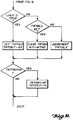
- the first step in the portion of the reset logic illustrated in FIGURE 10 is a test to determine if a term denoted LOGIC 3 is true.
- LOGIC 3 is true whenever the aircraft is not in a steady cruise state. More specifically, LOGIC 3 is true if a speed change has been commanded, the aircraft is offspeed, the aircraft is not in an altitude hold mode of operation, or if the aircraft is not tracking a specific speed command. If LOGIC 3 is true, the TNTHLD flag is set. Thereafter, a track integrator delay timer (TNTDLY) is set to a predetermined value (e.g., 20 seconds). Thus, as described below, the program tests the value of a TNTDLY timer.
- TNTDLY track integrator delay timer
- the TNTHLD flag is tested. If the TNTHLD flag is set, the TNTHLD flag is cleared. Then, the integrator value (INT) is set equal to the integrator held value (INTHD). Thereafter, the TNTDLY timer is tested. If the TNTHLD flag is not set, the TNTDLY timer is decremented. Thereafter, the program cycles to the TNTDLY timer test.
- the logic cycle is repeated. If the TNTDLY timer is equal to zero, the held integrator value (INTHD) is set equal to the integrator value (INT). Thereafter, the integrator delay timer (TNTDLY) is again set equal to a predetermined value (e.g., 20 seconds). Then, the logic cycle is repeated. The logic cycle may be repeated immediately or, if the logic cycle forms a portion of an overall program, it may be repeated after other steps of the overall program have taken place.
- INTHD the held integrator value
- TNTDLY integrator delay timer
- the filter network 85 includes two (twelfth and thirteenth) summers 93 and 95 and two first order filters 97 and 99.
- the twelfth and thirteenth summers 93 and 95 are both additive summers.
- the airspeed error i.e., the output of the tenth summer 81, is summed by the twelfth summer 93 with the longitudinal acceleration of the airplane.
- the result of the summation is filtered by one of the first order lag filters 97.
- the output of this first order lag filter 97 is summed by the thirteenth summer 95 with the longitudinal acceleration and the result of the summation is applied to the input of the other first order lag filter 99.
- the output of this first order lag filter is a complemented (i.e., filtered) airspeed error signal.
- both first order lag filters have a time constant of 10 and, thus, can be represented by the Laplace transform 1 10s + 1 .
- the output of the second first order lag filter 99 is applied through a fourth switch 101 and a second variable gain filter 103 to the second input of the eleventh summer 91.
- the third and fourth switches 87 and 101 are open when a thrust increment signal is being produced in the manner illustrated in FIGURE 6 and described above.
- a thrust increment produced as a result of a commanded airspeed change uniformly accelerates an airplane incorporating this invention to the commanded target airspeed.
- the gain of the first and second variable gain circuits 83 and 103 depends upon the magnitude of the input applied to the gain circuits, i.e., the magnitude of the airspeed error. If the airspeed error is less than a predetermined value, such as 3,7 km [ ⁇ 2 knots], the gain applied to the input signal is low--0.1, for example. Above a higher predetermined value, 18,52 km [ ⁇ 10 knots], for example, the gain applied to the input signal is higher--0.4, for example. A smooth ramp transition occurs between these limits, i.e., between 3,7 km [ ⁇ 2 knots] and 18,52 km [ ⁇ 10 knots].
- the output of the eleventh summer 91 is additively summed with the output of the sixth summer 39 by a fourteenth summer 105.
- the results of this summation are subtractively summed with the actual thrust generated by the aircraft's engines, as determined by a conventional engine thrust calculation circuit 107 by a fifteenth summer 109.
- the output of the fifteenth summer 109 which is the difference between the actual thrust and the predicted steady state thrust value modified in the manner heretofore described, is applied via a servo controller 111 to the throttle servo 113 of the engines 115.
- Sensors on the engines provide the signals utilized by the engine thrust calculation circuit 107 to determine actual thrust.
- this invention provides an automatic airspeed control system for airplane autothrottles that provides rapid, accurate thrust settings when an airplane is climbing, making a turn, encountering winds, and changing airspeed with a minimum of lag and error. These results are achieved by summing a predicted thrust value with thrust values based on the action taking place. If the aircraft is climbing, the thrust value to be summed is determined by the difference between climb thrust and cruise thrust modified by a factor that creates a smooth transition between climb and cruise. If a change in the airspeed of the airplane is commanded by the autopilot, an airspeed change thrust value is automatically summed with the predicted thrust value to create the thrust value used to control the thrust produced by the engines of the airplane. Similarly, if winds or movement of the aircraft, i.e., a turn, causes an airspeed error, a compensating thrust value is automatically generated and summed with the predicted thrust value to create the control thrust value.
Landscapes
- Engineering & Computer Science (AREA)
- Aviation & Aerospace Engineering (AREA)
- Radar, Positioning & Navigation (AREA)
- Remote Sensing (AREA)
- Physics & Mathematics (AREA)
- General Physics & Mathematics (AREA)
- Automation & Control Theory (AREA)
- Control Of Position, Course, Altitude, Or Attitude Of Moving Bodies (AREA)
Claims (18)
- Autodrossel, die einen vorhergesagten bzw. vorausgesetzten Stationärzustands-Schubwert für die Verwendung beim Steuern bzw. Regeln des durch die Triebwerke eines Flugzeugs erzeugten Schubs erzeugt, gekennzeichnet durch ein automatisches Eigengeschwindigkeitsteuer- bzw. -regelsystem, umfassend:ein Modifizierungsmittel (29, 39) zum Modifizieren des vorausgesagten bzw. vorausgesetzten Stationärzustands-Schubwerts mit inkrementellen Schubwerten basierend auf Eigengeschwindigkeitsfehlern und Höhenänderungen; undein Feinabstimmittel (91, 105) zum Feinabstimmen des modifizierten, vorausgesagten bzw. vorausgesetzten Stationärzustands-Schubwerts basierend auf der Differenz (81) zwischen der aktuellen Eigengeschwindigkeit eines Flugzeugs und der gewünschten Eigengeschwindigkeit des Flugzeugs.
- Autodrossel nach Anspruch 1, worin das Modifizierungsmittel folgendes umfaßt:ein Mittel (23) zum Erzeugen eines Vorhalt- bzw. Voraussagekorrekturwerts basierend auf der Differenz zwischen dem vorausgesagten bzw. vorausgesetzten Stationärzustandsschub und dem aktuellen Schub, der durch die Triebwerke des Flugzeugs beim Reiseflug erzeugt wird; undein erstes Summmierungsmittel (27) zum Summieren des vorausgesagten bzw. vorausgesetzten Stationärzustands-Schubwerts mit dem vorausgesagten bzw. vorausgesetzten Korrekturwert zum Erzeugen eines korrigierten vorausgesagten bzw. vorausgesetzten Stationärzustands-Schubwerts.
- Autodrossel nach Anspruch 1 oder 2, worin das Modifizierungsmittel ein zweites Summierungsmittel (29) zum Summieren eines Höhenerreichungsänderungs-Schubwerts mit dem korrigierten, vorausgesagten bzw. vorausgesetzten Stationärzustands-Schubwert umfaßt.
- Autodrossel nach Anspruch 3, worin der Höhenerreichungsänderungs-Schubwert bestimmt (37) wird durch Multiplizieren der Differenz zwischen dem Schub, der von dem Flugzeug zum Steigen von einer Ausgangshöhe zu einer zu erreichenden Reiseflughöhe benötigt wird, minus dem Schub bei der Reiseflughöhe mit einem Glättungsfaktor.
- Autodrossel nach Anspruch 4, worin der Glättungsfaktor bestimmt (37) wird durch Ermitteln der Quadratwurzel aus der Differenz (35) zwischen der zu erreichenden Reiseflughöhe und der gegenwärtigen Höhe, geteilt durch die Differenz (33) zwischen der zu erreichenden Reiseflughöhe und der Ausgangshöhe.
- Autodrossel nach Anspruch 1, 2, 3, 4 oder 5, worin das Feinabstimmittel folgendes umfaßt:ein drittes Summierungsmittel (81) zum Bestimmen der Differenz zwischen der aktuellen Eigengeschwindigkeit des Flugzeugs und der befohlenen (Ziel-)Eigengeschwindigkeit; undein Mittel (83) variablen Verstärkungsgrads zum Modifizieren der Amplitude der Differenz zwischen der aktuellen Eigengeschwindigkeit und der Zieleigengeschwindigkeit basierend auf der Differenz zwischen denselben.
- Autodrossel nach Anspruch 6, worin:(a) das Mittel (83) variablen Verstärkungsgrads folgendes umfaßt:(i) zwei Kanäle, wobei einer der Kanäle einen Integrator (89) zum Integrieren der Eigengeschwindigkeitsdifferenz aufweist, während der andere der Kanäle ein Filter (85) zum Filtern der Eigengeschwindigkeitsdifferenz aufweist und beide Kanäle einen Verstärker (103) variablen Verstärkungsgrads aufweisen; und(ii) ein viertes Summierungsmittel (91) zum Summieren der Ausgangsgrößen der Kanäle zur Bildung eines Feinabstimmwerts; und(b) das Feinabstimmittel außerdem ein fünftes Summierungsmittel (105) zum Summieren der Ausgangsgröße des zweiten Summierungsmittels (29) mit dem von dem vierten Summierungsmittel (91) gebildeten Feinabstimmwert aufweist.
- Autodrossel nach Anspruch 7, worin das Feinabstimmittel außerdem eine Rücksetzlogik (90) aufweist zum Rücksetzen des Integrators (89) unter vorbestimmten Bedingungen auf entweder Null oder den letzten von dem Integrator erzeugten Wert.
- Autodrossel nach Anspruch 8, worin die vorbestimmten Bedingungen folgendes umfassen:Rücksetzen sowohl des Integrators (89) als auch des letzten Werts des Integrators auf Null, wenn das Flugzeug nicht in einer Höhenhaltebetriebsweise ist und die Autodrossel abgeschaltet ist; undder Integrator (89) auf den letzten Wert des Integrators gesetzt wird, wann immer die Autodrossel des Flugzeugs befiehlt, daß die Eigengeschwindigkeit des Flugzeugs in einen "Auf-Geschwindigkeit"-Zustand zurückkehren soll.
- Autodrossel, wie in den Ansprüchen 1 bis 9 beansprucht, worin das Modifizierungsmittel ein sechstes Summierungsmittel (39) zum Summieren eines EigengeschwindigkeitsänderungsSchubinkrementwerts, basierend entweder auf einer Änderung in der befohlenen (Ziel-)Flugzeuggeschwindigkeit des Flugzeugs oder einer Änderung in der Geschwindigkeit des Flugzeugs, die nicht aus einer Änderung in der befohlenen (Ziel-)Eigengeschwindigkeit resultiert, mit dem korrigierten, vorausgesagten bzw. vorausgesetzten Stationärzustands-Schubwert (29) umfaßt.
- Autodrossel nach Anspruch 10, worin der Eigengeschwindigkeitsänderungs-Schubinkrementwert bestimmt (Fig. 5 und 6) wird durch Bestimmen, ob eine Änderung in der Eigengeschwindigkeit auf einer befohlenen (Ziel-)Eigengeschwindigkeitsänderung oder einer nichtbefohlenen (Ziel-)Flugzeuggeschwindigkeitsänderung basiert, und Steuern bzw. Regeln des Eigengeschwindigkeitsänderungs-Schubinkrementwerts gemäß der genannten Bestimmung.
- Autodrossel nach Anspruch 11, worin die Bestimmung (43, 51, 52, 53, 54) gemacht wird durch Bestimmen, ob die Änderungsrate der Eigengeschwindigkeit langsam oder schnell ist, wobei schnelle Eigengeschwindigkeitsänderungen eine Änderung in der befohlenen (Ziel-)Flugzeuggeschwindigkeit angeben und langsame Eigengeschwindigkeitsänderungen eine Änderung in einer nichtbefohlenen (Ziel-)Flugzeuggeschwindigkeit angeben.
- Autodrossel nach Anspruch 12, umfassend ein siebentes Summierungsmittel (43) zum Summieren der aktuellen Eigengeschwindigkeit des Flugzeugs mit der befohlenen (Ziel-)Eigengeschwindigkeit des Flugzeugs zum Bestimmen des Fehlers zwischen denselben, und umfassend ein Hysteresemittel (51-54) zum Erzeugen von Geschwindigkeitsänderungssteuer- bzw. -regelsignalen, wenn der genannte Fehler über einen speziellen Wert ansteigt, und Beenden der Geschwindigkeitsänderungssteuer- bzw. -regelsignale, wenn der genannte Fehler unter einen vorbestimmten Wert abfällt.
- Autodrossel nach Anspruch 13, worin das Hysteresemittel (51-54) vier Geschwindigkeitsänderungssignale erzeugt, wobei zwei der Geschwindigkeitsänderungssignale erzeugt werden, wenn eine Änderung in der Eigengeschwindigkeit auf einer befohlenen (Ziel-)Flugzeuggeschwindigkeitsänderung basiert, und zwei der Geschwindigkeitsänderungssignale erzeugt werden, wenn eine Änderung in der Eigengeschwindigkeit nicht auf einer befohlenen (Ziel-)Flugzeuggeschwindigkeitsänderung basiert.
- Autodrossel nach Anspruch 14, worin eines der Geschwindigkeitsänderungssignale, das erzeugt wird, wenn eine Änderung in der Eigengeschwindigkeit auf einer befohlenen (Ziel-)Flugzeuggeschwindigkeitsänderung basiert, erzeugt wird, wenn der Geschwindigkeitsfehler oberhalb eines ersten vorbestimmten Niveaus ist, und worin das andere der Geschwindigkeitsänderungssignale, das erzeugt wird, wenn eine Änderung in der Eigengeschwindigkeit auf einer befohlenen (Ziel-)Flugzeuggeschwindigkeitsänderung basiert, erzeugt wird, wenn der Geschwindigkeitsfehler oberhalb eines zweiten vorbestimmten Niveaus ist, wobei das zweite vorbestimmte Niveau größer als das erste vorbestimmte Niveau ist.
- Autodrossel nach Anspruch 15, worin eines der Geschwindigkeitsänderungssignale, das erzeugt wird, wenn eine Änderung in der Eigengeschwindigkeit nicht auf einer befohlenen (Ziel-)Flugzeuggeschwindigkeit basiert, erzeugt wird, wenn der Geschwindigkeitsfehler oberhalb eines ersten vorbestimmten Niveaus ist, und worin das andere Geschwindigkeitsänderungssignal, das erzeugt wird, wenn eine Änderung in der Eigengeschwindigkeit nicht auf einer befohlenen (Ziel-)-Flugzeuggeschwindigkeit basiert, erzeugt wird, wenn der Geschwindigkeitsfehler über ein zweites vorbestimmtes Niveau ansteigt, wobei das zweite vorbestimmte Niveau größer als das erste vorbestimmte Niveau ist.
- Autodrossel nach Anspruch 16, worin der Eigengeschwindigkeitsänderungs-Schubinkrementwert basiert auf einem für eine Höhe korrigierten (61) normierten Schubwert, multipliziert (63-69) mit einem Faktor, dessen Größe auf dem Zustand der Geschwindigkeitsänderungssignale basiert.
- Autodrossel nach Anspruch 8, worin die Rückstellogik (90) den Integrator (89) nicht auf Null oder den letzten von dem Integrator erzeugten Wert zurückstellt, wenn die Differenz zwischen der Absolutgeschwindigkeit und der Eigengeschwindigkeit unter einem vorbestimmten Wert liegt.
Priority Applications (2)
| Application Number | Priority Date | Filing Date | Title |
|---|---|---|---|
| EP90202852A EP0482250B1 (de) | 1990-10-25 | 1990-10-25 | Luftgeschwindigkeitsregelsystem für Flugzeugvortriebsregler |
| DE69024958T DE69024958T2 (de) | 1990-10-25 | 1990-10-25 | Luftgeschwindigkeitsregelsystem für Flugzeugvortriebsregler |
Applications Claiming Priority (1)
| Application Number | Priority Date | Filing Date | Title |
|---|---|---|---|
| EP90202852A EP0482250B1 (de) | 1990-10-25 | 1990-10-25 | Luftgeschwindigkeitsregelsystem für Flugzeugvortriebsregler |
Publications (2)
| Publication Number | Publication Date |
|---|---|
| EP0482250A1 EP0482250A1 (de) | 1992-04-29 |
| EP0482250B1 true EP0482250B1 (de) | 1996-01-17 |
Family
ID=8205154
Family Applications (1)
| Application Number | Title | Priority Date | Filing Date |
|---|---|---|---|
| EP90202852A Expired - Lifetime EP0482250B1 (de) | 1990-10-25 | 1990-10-25 | Luftgeschwindigkeitsregelsystem für Flugzeugvortriebsregler |
Country Status (2)
| Country | Link |
|---|---|
| EP (1) | EP0482250B1 (de) |
| DE (1) | DE69024958T2 (de) |
Families Citing this family (10)
| Publication number | Priority date | Publication date | Assignee | Title |
|---|---|---|---|---|
| FR2845350B1 (fr) * | 2002-10-02 | 2004-12-17 | Airbus France | Procede et dispositif pour commander automatiquement la pousse d'au moins un moteur d'un aeronef lors d'une phase de vol horizontal a vitesse stabilisee |
| US7127335B2 (en) * | 2003-03-25 | 2006-10-24 | Rosemount Aerospace Inc. | Low airspeed assist algorithm for air data computer applications |
| US9085371B2 (en) | 2008-11-20 | 2015-07-21 | The Boeing Company | Automatic throttle roll angle compensation |
| US9058040B2 (en) * | 2009-02-27 | 2015-06-16 | The Boeing Company | Automatic pilot pitch angle compensation |
| FR2973777B1 (fr) * | 2011-04-07 | 2014-04-18 | Airbus Operations Sas | Dispositif de protection d'energie pour un aeronef. |
| FR3029570B1 (fr) | 2014-12-05 | 2019-08-30 | Safran Aircraft Engines | Dispositif et procede de regulation d'un moteur exploitant une mesure de poussee |
| FR3036507A1 (fr) * | 2015-05-18 | 2016-11-25 | Airbus Operations Sas | Procede et systeme de gestion automatique d'une auto-poussee d'un aeronef. |
| US10101749B1 (en) | 2017-03-21 | 2018-10-16 | Bell Helicopter Textron Inc. | Combined airspeed and inertial data for rotorcraft longitudinal control |
| US11377223B2 (en) * | 2018-10-29 | 2022-07-05 | Pratt & Whitney Canada Corp. | Autothrottle control system on turbopropeller-powered aircraft |
| US11299285B2 (en) | 2018-12-20 | 2022-04-12 | Honeywell International Inc. | Systems and methods for providing throttle guidance as a function of flight path acceleration |
Family Cites Families (3)
| Publication number | Priority date | Publication date | Assignee | Title |
|---|---|---|---|---|
| US4266743A (en) * | 1979-02-28 | 1981-05-12 | The United States Of America As Represented By The Administrator Of The National Aeronautics And Space Administration | Pitch attitude stabilization system utilizing engine pressure ratio feedback signals |
| GB2088961B (en) * | 1980-11-26 | 1984-06-13 | Rolls Royce | Fuel control system for a gas turbine engine |
| US4993221A (en) * | 1988-12-21 | 1991-02-19 | General Electric Company | Gas turbine engine control system |
-
1990
- 1990-10-25 EP EP90202852A patent/EP0482250B1/de not_active Expired - Lifetime
- 1990-10-25 DE DE69024958T patent/DE69024958T2/de not_active Expired - Fee Related
Also Published As
| Publication number | Publication date |
|---|---|
| DE69024958D1 (de) | 1996-02-29 |
| EP0482250A1 (de) | 1992-04-29 |
| DE69024958T2 (de) | 1996-05-30 |
Similar Documents
| Publication | Publication Date | Title |
|---|---|---|
| US4019702A (en) | Method and apparatus for guiding a jet aircraft in a noise-abated post-takeoff climb | |
| EP0031619B1 (de) | System zum Steuern des vertikalen Flugweges eines Flugzeuges | |
| Holzhuter | LQG approach for the high-precision track control of ships | |
| US4924401A (en) | Aircraft ground collision avoidance and autorecovery systems device | |
| US5195700A (en) | Low speed model following velocity command system for rotary wing aircraft | |
| EP0482250B1 (de) | Luftgeschwindigkeitsregelsystem für Flugzeugvortriebsregler | |
| US3652835A (en) | Aircraft glide slope coupler system | |
| US4093158A (en) | Airplane instrument with throttle control selectively regulated by air speed or lift | |
| EP0028435B1 (de) | Flugzeugaufsteigsteuerungssystem | |
| US4277041A (en) | Aircraft cruise speed control system | |
| US3681580A (en) | Rotation,climbout,and go-around control system | |
| US4422147A (en) | Wind shear responsive turbulence compensated aircraft throttle control system | |
| US3981442A (en) | Aircraft engine automatic throttle control with automatic gain programming system | |
| US4488235A (en) | Speed control system for aircraft | |
| EP0743584B1 (de) | Flugzeug-Regelsystem für vertikale Position | |
| US4609988A (en) | Automatic prediction and capture of a preselected altitude for aircraft | |
| EP0224279B1 (de) | Vorrichtung und Verfahren zum Generieren von Steuerbefehlen für ein Flugzeug unter Verwendung einer Rückkopplung mit nichtlinearer Verstärkung | |
| GB951735A (en) | Self-adaptive control system | |
| Liden | Optimum 4D guidance for long flights | |
| EP0444541B1 (de) | Verfahren und Vorrichtung zu einem allmählichen Übergang zwischen einer kalibrierten Luftgeschwindigkeitssteuerung und einer Machzahlsteuerung eines Flugzeuges | |
| US5117362A (en) | Path capture forcing function generator for aircraft vertical axis control | |
| US3545703A (en) | System for controlling flight of aircraft to attain a predetermined altitude | |
| US3327306A (en) | Optimized input adaptive control method and system | |
| US5111403A (en) | Terrain compensation method and apparatus for aircraft automatic landing systems | |
| US4672548A (en) | Speed capture in climb for aircraft |
Legal Events
| Date | Code | Title | Description |
|---|---|---|---|
| PUAI | Public reference made under article 153(3) epc to a published international application that has entered the european phase |
Free format text: ORIGINAL CODE: 0009012 |
|
| AK | Designated contracting states |
Kind code of ref document: A1 Designated state(s): DE FR GB IT NL |
|
| 17P | Request for examination filed |
Effective date: 19921028 |
|
| 17Q | First examination report despatched |
Effective date: 19940622 |
|
| GRAA | (expected) grant |
Free format text: ORIGINAL CODE: 0009210 |
|
| AK | Designated contracting states |
Kind code of ref document: B1 Designated state(s): DE FR GB IT NL |
|
| PG25 | Lapsed in a contracting state [announced via postgrant information from national office to epo] |
Ref country code: IT Free format text: LAPSE BECAUSE OF FAILURE TO SUBMIT A TRANSLATION OF THE DESCRIPTION OR TO PAY THE FEE WITHIN THE PRE;WARNING: LAPSES OF ITALIAN PATENTS WITH EFFECTIVE DATE BEFORE 2007 MAY HAVE OCCURRED AT ANY TIME BEFORE 2007. THE CORRECT EFFECTIVE DATE MAY BE DIFFERENT FROM THE ONE RECORDED.SCRIBED TIME-LIMIT Effective date: 19960117 |
|
| REF | Corresponds to: |
Ref document number: 69024958 Country of ref document: DE Date of ref document: 19960229 |
|
| ET | Fr: translation filed | ||
| PLBE | No opposition filed within time limit |
Free format text: ORIGINAL CODE: 0009261 |
|
| STAA | Information on the status of an ep patent application or granted ep patent |
Free format text: STATUS: NO OPPOSITION FILED WITHIN TIME LIMIT |
|
| 26N | No opposition filed | ||
| REG | Reference to a national code |
Ref country code: GB Ref legal event code: IF02 |
|
| PGFP | Annual fee paid to national office [announced via postgrant information from national office to epo] |
Ref country code: NL Payment date: 20050929 Year of fee payment: 16 |
|
| PG25 | Lapsed in a contracting state [announced via postgrant information from national office to epo] |
Ref country code: NL Free format text: LAPSE BECAUSE OF NON-PAYMENT OF DUE FEES Effective date: 20070501 |
|
| NLV4 | Nl: lapsed or anulled due to non-payment of the annual fee |
Effective date: 20070501 |
|
| PGFP | Annual fee paid to national office [announced via postgrant information from national office to epo] |
Ref country code: DE Payment date: 20081201 Year of fee payment: 19 |
|
| PGFP | Annual fee paid to national office [announced via postgrant information from national office to epo] |
Ref country code: FR Payment date: 20081018 Year of fee payment: 19 |
|
| PGFP | Annual fee paid to national office [announced via postgrant information from national office to epo] |
Ref country code: GB Payment date: 20081029 Year of fee payment: 19 |
|
| REG | Reference to a national code |
Ref country code: FR Ref legal event code: ST Effective date: 20100630 |
|
| PG25 | Lapsed in a contracting state [announced via postgrant information from national office to epo] |
Ref country code: FR Free format text: LAPSE BECAUSE OF NON-PAYMENT OF DUE FEES Effective date: 20091102 Ref country code: DE Free format text: LAPSE BECAUSE OF NON-PAYMENT OF DUE FEES Effective date: 20100501 |
|
| PG25 | Lapsed in a contracting state [announced via postgrant information from national office to epo] |
Ref country code: GB Free format text: LAPSE BECAUSE OF NON-PAYMENT OF DUE FEES Effective date: 20091025 |