EP0482264B1 - Mechanismus zum Sperren und Entsperren von Verschlussbolzen für automatische Aufzugstüren - Google Patents
Mechanismus zum Sperren und Entsperren von Verschlussbolzen für automatische Aufzugstüren Download PDFInfo
- Publication number
- EP0482264B1 EP0482264B1 EP19900402650 EP90402650A EP0482264B1 EP 0482264 B1 EP0482264 B1 EP 0482264B1 EP 19900402650 EP19900402650 EP 19900402650 EP 90402650 A EP90402650 A EP 90402650A EP 0482264 B1 EP0482264 B1 EP 0482264B1
- Authority
- EP
- European Patent Office
- Prior art keywords
- door
- roller
- bolt
- floor
- cabin
- Prior art date
- Legal status (The legal status is an assumption and is not a legal conclusion. Google has not performed a legal analysis and makes no representation as to the accuracy of the status listed.)
- Expired - Lifetime
Links
- 230000007246 mechanism Effects 0.000 title claims description 28
- 238000006073 displacement reaction Methods 0.000 claims description 6
- 230000009471 action Effects 0.000 description 3
- 238000010586 diagram Methods 0.000 description 3
- 238000000034 method Methods 0.000 description 3
- 230000008569 process Effects 0.000 description 3
- 230000009467 reduction Effects 0.000 description 3
- 239000000872 buffer Substances 0.000 description 2
- 230000000694 effects Effects 0.000 description 2
- 230000008030 elimination Effects 0.000 description 2
- 238000003379 elimination reaction Methods 0.000 description 2
- 230000005484 gravity Effects 0.000 description 2
- 238000012423 maintenance Methods 0.000 description 2
- 230000007257 malfunction Effects 0.000 description 2
- 238000000429 assembly Methods 0.000 description 1
- 230000005540 biological transmission Effects 0.000 description 1
- 239000000470 constituent Substances 0.000 description 1
- 230000000284 resting effect Effects 0.000 description 1
- 239000007787 solid Substances 0.000 description 1
- 239000013589 supplement Substances 0.000 description 1
Images
Classifications
-
- B—PERFORMING OPERATIONS; TRANSPORTING
- B66—HOISTING; LIFTING; HAULING
- B66B—ELEVATORS; ESCALATORS OR MOVING WALKWAYS
- B66B13/00—Doors, gates, or other apparatus controlling access to, or exit from, cages or lift well landings
- B66B13/02—Door or gate operation
- B66B13/12—Arrangements for effecting simultaneous opening or closing of cage and landing doors
Definitions
- the present invention relates to a mechanism for locking and releasing closure bolts for automatic doors of lifts, the special design of the mechanism providing a number of advantages from the structural point of view as well as the functional and including the maintenance aspect, compared with conventional systems provided for the same purpose.
- the locking mechanism is constructed so that it permits a movement of the doors on each floor and of the lifts and of the cabin doors, being firmly connected to one another without any play, during periods of opening and closing. At the same time, the structure of the mechanism is reduced to the minimum in terms of the number of constituent parts, basically in the floor door of the lift.
- the invention has conceived a locking and release mechanism applicable to automatic doors of lifts for the actuation of the closure bolts, which allows movement of the lift doors at the floor and also of the door of the lift cabin, the doors being firmly connected with no clearance in either direction of movement and during the periods of opening and closure.
- the mechanism is based on a considerable reduction in the number of elementary parts such as rollers, spindles, moving parts etc., mainly in the lift door at the floor.
- the mechanism has the particular feature that the buffers for carrying out the said locking and releasing of the bolt are constituted by respective flat and rectangular profiles, one of these belonging to the door at the floor while the other belongs to the door of the lift, between which there is disposed a roller which is rigid with the floor door and on the top and rear of which rests the associated bolt, while externally of the flat profile which is attached to the floor door there is another roller connected to a tilting member which is actuated by the thrust from a straight arm which is part of the cabin door, all so that the distances, in the closed position, between the roller connected to the floor door and the flat profile connected to the cabin door, and also the distance between the roller connected to the cabin door and the flat profile rigid with the floor door, are constant and equal distances which allows the doors to be connected without any clearance of any type, so that no noises are created while smooth movements are obtained without any kind of rattling in the door panels.
- this invention relates to a mechanism for locking and releasing closure bolts for automatic doors of lifts, which being envisaged to produce a tilting of the bolt by means of which it is possible to lock and/or release the corresponding floor door to prevent or allow respectively the opening of the said door, characterised in that the aforesaid bolt has its upper and rear part bearing on a roller provided on the floor door, on which roller it is possible for a flat rectangular profile in a vertical disposition to bear and press, the said profile belonging to the cabin door, with the particular feature that on this cabin door there is in turn mounted a second roller which is disposed on a tilting member, a roller which is capable of biasing and pressing on a second flat rectangular profile in the vertical position, belonging to the floor door, there being also provision for the said tilting member to be also provided with a new roller which is capable of being acted on and biased at the end of a straight arm belonging to the cabin door, all so that the displacement of the flat profile belonging to the cabin door when the door opening phase commences, and the displacement
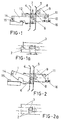
- Figs. 1 and 1a show the mechanism in the closed position at the moment when the opening operation is about to commence, so that in the diagram in Fig. 1a there are clearly shown the constant distances which were referred to hereinabove, between the flat profiles connected to the doors and the corresponding rollers which form part of the mechanism.
- Figs. 2 and 2a show the same diagrams as those shown in Figs. 1 and 1a but in the position of tilting of the bolt in order to release and correspondingly open the door.
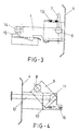
- Fig. 3 is a side view of the bolt in its locked position associated with the roller on the top of which it rests, also showing the flat profile corresponding to the cabin door.
- Fig. 4 is a side view of the rear part of the mechanism and showing the tilting part as well as the form of thrust of the flat profile corresponding to the cabin door.
- reference numeral 2 corresponds to the cabin door while reference 3 corresponds to the door at the floor or storey, the references "a” and “2a” corresponding to the distances between the elements which form part of the mechanism and which will be described hereinafter.
- the actual mechanism includes a flat and rectangular profile 4 which is connected to the cabin door and a similar profile 5 which is connected to the door on the floor or storey, so that Fig. 1 shows the bolt 1 in the locked position and immediately prior to commencement of the movements needed to open or release it.
- the bolt 1 has its upper and rear part resting on a roller 6 which is connected to the floor door 3, the roller 6 on which it is possible to support and impel a flat and rectangular profile into a vertical arrangement identified by reference numeral 7 and belonging to the cabin door 2.
- a second roller 8 is also mounted on this cabin door 2, with the particular feature that in this case the said roller 8 is associated with a tilting member 9 which rotates about the spindle 10.
- the said roller 8 is, according to the tilting of the member 9, capable of acting upon and biasing the end of a straight arm 12 which is part of the cabin door 2, all so that displacement of the profiles 4 and 5 by the action of the rollers 6 and 8 produces a tilting of the bolt 1 in order to release and open the door, in addition to which the connection between them is made without any kind of clearance.
- Fig. 3 shows the actual bolt 1 in the closed or locked position, clearly demonstrating how the member 7 is constantly biased by a spring 13, the said bolt being associated with a contact 14 combined with a make-and-break switch 15.
- Fig. 4 shows the rear part of the mechanism where it is possible to see the tilting member 8 and the arm 12 which bears on the roller 11, the said tilting member 9 being biased by the spring 16.
- the bolt 1 During the process of opening and closing, the bolt 1 will be permanently subject to the control of displacement of the cabin door 2 and therefore its movement is never free, which avoids the typical problem of the noise caused in other mechanisms due to the uncontrolled dropping of the bolt during the final phase of door closure.
Landscapes
- Elevator Door Apparatuses (AREA)
- Lock And Its Accessories (AREA)
Claims (3)
- Vorrichtung zum Sperren und Entsperren von Schließbolzen automatischer Aufzugstüren, die vorgesehen ist, ein Kippen des Bolzens (1) zu bewirken, durch den es möglich ist, die entsprechende Stockwerkstüre (3) zu versperren und/oder zu entsperren, um das Öffnen der genannten Türe (3) zu verhindern bzw. zu ermöglichen,
dadurch gekennzeichnet,
daß sich der obere und hintere Teil des genannten Bolzens (1) an eine an der Stockwerkstüre (3) vorgesehene Rolle (6) anlegt, gegen die ein flaches rechtwinkliges Profil (4) in einer vertikalen Anordnung sich anlegen und drücken kann, wobei das genannte Profil (4) zu der Kabinentüre (2) gehört mit dem besonderen Merkmal, daß an dieser Kabinentüre (2) ihrerseits eine zweite Rolle (8) angebracht ist, die an einem Kippteil (9) angeordnet ist, eine Rolle (6), die ein zweites, flaches, rechtwinkliges Profil (5) in vertikaler Anordnung belasten und gegen dieses drücken kann, das zu der Stockwerkstüre (3) gehört, und wobei außerdem vorgesehen ist, daß das Kippteil (9) auch mit einer neuen Rolle (11) versehen ist, auf die an dem Ende eines zu der Kabinentüre (2) gehörenden, geraden Arms (12) eingewirkt werden kann und die belastet werden kann, alles so, daß die Verlagerung des zu der Kabinentüre (2) gehörenden, flachen Profils (4) zu Beginn der Türöffnungs-Phase und die Verlagerung der zur Stockwerkstüre (3) gehörenden Rolle (6), die durch das flache Profil (4) geschoben wird, ein Kippen des Schließbolzens (1) bewirkt, was die Stockwerkstüre (3) entsperrt und eine Verdrehung des Kippteils (9) bewirkt, so daß die zweite Rolle (8) an das flache Profil (5) der Stockwerkstüre (3) herankommt und ein abstandsfreies Verbinden der zwei Türen (2,3) erlaubt. - Vorrichtung zum Sperren und Entsperren von Schließbolzen automatischer Aufzugstüren nach Anspruch 1,
dadurch gekennzeichnet,
daß im Schließzustand des Bolzens (1) der Abstand (9) zwischen dem flachen Profil (4) der Kabine und der Rolle (6) der Stockwerkstüre (3) gleich ist dem Abstand (9) zwischen dem flachen Profil dieser Stockwerkstüre (3) und der ersten Rolle des Kippteils, das zu der Kabinentüre gehört. - Vorrichtung zum Sperren und Entsperren von Schließbolzen automatischer Aufzugstüren nach Ansprüchen 1 und 2,
dadurch gekennzeichnet,
daß die Kippwelle des Bolzens (1) unter der Rolle (6) der Stockwerkstüre (3) angeordnet ist, die sich an den Bolzen (1) anlegt, während die Kippachse (10) des Kippteils (9), mit der die Kabinentürrolle verbunden ist, unter der zweiten Rolle (8) des Kippteils (9) angeordnet ist.
Applications Claiming Priority (1)
| Application Number | Priority Date | Filing Date | Title |
|---|---|---|---|
| ES898902664A ES2016721A6 (es) | 1989-07-27 | 1989-07-27 | Mecanismo de bloqueo y liberacion de pestillos de cierre para puertas automaticas de ascensores. |
Publications (2)
| Publication Number | Publication Date |
|---|---|
| EP0482264A1 EP0482264A1 (de) | 1992-04-29 |
| EP0482264B1 true EP0482264B1 (de) | 1994-06-08 |
Family
ID=8263315
Family Applications (1)
| Application Number | Title | Priority Date | Filing Date |
|---|---|---|---|
| EP19900402650 Expired - Lifetime EP0482264B1 (de) | 1989-07-27 | 1990-09-26 | Mechanismus zum Sperren und Entsperren von Verschlussbolzen für automatische Aufzugstüren |
Country Status (3)
| Country | Link |
|---|---|
| EP (1) | EP0482264B1 (de) |
| BR (1) | BR9004824A (de) |
| ES (1) | ES2016721A6 (de) |
Families Citing this family (3)
| Publication number | Priority date | Publication date | Assignee | Title |
|---|---|---|---|---|
| US5427204A (en) * | 1993-11-01 | 1995-06-27 | Otis Elevator Company | Elevator hoistway and car door lock and coupling |
| IT1316302B1 (it) * | 2000-01-26 | 2003-04-10 | Sematic Italia Spa | Serratura modulare per porte di ascensori |
| KR200462913Y1 (ko) | 2010-07-21 | 2012-10-11 | 현대엘리베이터주식회사 | 엘리베이터의 인터록 장치 |
Family Cites Families (2)
| Publication number | Priority date | Publication date | Assignee | Title |
|---|---|---|---|---|
| CH663406A5 (de) * | 1984-05-28 | 1987-12-15 | Inventio Ag | Tuerantriebsvorrichtung mit verriegelungsmechanismus fuer aufzuege. |
| ES2016722A6 (es) * | 1989-07-27 | 1990-11-16 | Otis Elevator Co | Mecanismo de bloqueo y liberacion de pestillos de cierre para puertas de ascensores con paneles alineados. |
-
1989
- 1989-07-27 ES ES898902664A patent/ES2016721A6/es not_active Expired - Lifetime
-
1990
- 1990-09-26 EP EP19900402650 patent/EP0482264B1/de not_active Expired - Lifetime
- 1990-09-26 BR BR9004824A patent/BR9004824A/pt not_active IP Right Cessation
Also Published As
| Publication number | Publication date |
|---|---|
| ES2016721A6 (es) | 1990-11-16 |
| BR9004824A (pt) | 1991-09-10 |
| EP0482264A1 (de) | 1992-04-29 |
Similar Documents
| Publication | Publication Date | Title |
|---|---|---|
| FI96676C (fi) | Hissin korinoven lukituslaitteisto ja menetelmä korinoven lukitsemiseksi ja vapauttamiseksi | |
| US4530184A (en) | Sliding type door assembly | |
| JP2554702B2 (ja) | ドアーロック | |
| FI83802C (fi) | Elektromekaniskt doerrlaos. | |
| US20100276945A1 (en) | Locking device of a door | |
| US6826869B2 (en) | Powered sliding panel with secondary articulation for a motor vehicle | |
| JPH11247513A (ja) | 自動車ドアロック | |
| JPH0676184B2 (ja) | エレベータケージ | |
| KR20210021658A (ko) | 파워 차일드 록 장치 | |
| EP0482264B1 (de) | Mechanismus zum Sperren und Entsperren von Verschlussbolzen für automatische Aufzugstüren | |
| DE19611972B4 (de) | Türverriegelungsvorrichtung | |
| JPS61501936A (ja) | 自動車のドア開閉装置 | |
| WO1997031853A1 (en) | Door coupler and locking device | |
| JPH0361284A (ja) | 整合パネルを有するエレベータドアーロックのブロッキング及び解放機構 | |
| CN109914945B (zh) | 车辆门机械锁装置 | |
| HK1697A (en) | Door coupling device | |
| EP0762986B1 (de) | Manuelle notöffnungsvorrichtung für automatische türen, insbesondere für lift-und aufzugstüren | |
| EP4505030B1 (de) | Kraftfahrzeugschloss, insbesondere kraftfahrzeugtürschloss | |
| JP3769641B2 (ja) | ドアロック制御機構 | |
| JPH0117446Y2 (de) | ||
| KR200247113Y1 (ko) | 자동차용 도어의 자동잠금장치 | |
| JPH046478Y2 (de) | ||
| JPH0542216Y2 (de) | ||
| JPH03200688A (ja) | 扉安全装置 | |
| DE102022113058A1 (de) | Kraftfahrzeug-Schloss insbesondere Kraftfahrzeug-Türschloss |
Legal Events
| Date | Code | Title | Description |
|---|---|---|---|
| PUAI | Public reference made under article 153(3) epc to a published international application that has entered the european phase |
Free format text: ORIGINAL CODE: 0009012 |
|
| AK | Designated contracting states |
Kind code of ref document: A1 Designated state(s): FR IT |
|
| 17P | Request for examination filed |
Effective date: 19920408 |
|
| R17P | Request for examination filed (corrected) |
Effective date: 19920408 |
|
| 17Q | First examination report despatched |
Effective date: 19930416 |
|
| GRAA | (expected) grant |
Free format text: ORIGINAL CODE: 0009210 |
|
| ITF | It: translation for a ep patent filed | ||
| AK | Designated contracting states |
Kind code of ref document: B1 Designated state(s): FR IT |
|
| ET | Fr: translation filed | ||
| PLBE | No opposition filed within time limit |
Free format text: ORIGINAL CODE: 0009261 |
|
| STAA | Information on the status of an ep patent application or granted ep patent |
Free format text: STATUS: NO OPPOSITION FILED WITHIN TIME LIMIT |
|
| 26N | No opposition filed | ||
| PGFP | Annual fee paid to national office [announced via postgrant information from national office to epo] |
Ref country code: FR Payment date: 19970811 Year of fee payment: 8 |
|
| PG25 | Lapsed in a contracting state [announced via postgrant information from national office to epo] |
Ref country code: FR Free format text: LAPSE BECAUSE OF NON-PAYMENT OF DUE FEES Effective date: 19990531 |
|
| REG | Reference to a national code |
Ref country code: FR Ref legal event code: ST |
|
| PG25 | Lapsed in a contracting state [announced via postgrant information from national office to epo] |
Ref country code: IT Free format text: LAPSE BECAUSE OF NON-PAYMENT OF DUE FEES;WARNING: LAPSES OF ITALIAN PATENTS WITH EFFECTIVE DATE BEFORE 2007 MAY HAVE OCCURRED AT ANY TIME BEFORE 2007. THE CORRECT EFFECTIVE DATE MAY BE DIFFERENT FROM THE ONE RECORDED. Effective date: 20050926 |