EP0482282A1 - Support de manchette axial - Google Patents
Support de manchette axial Download PDFInfo
- Publication number
- EP0482282A1 EP0482282A1 EP91104177A EP91104177A EP0482282A1 EP 0482282 A1 EP0482282 A1 EP 0482282A1 EP 91104177 A EP91104177 A EP 91104177A EP 91104177 A EP91104177 A EP 91104177A EP 0482282 A1 EP0482282 A1 EP 0482282A1
- Authority
- EP
- European Patent Office
- Prior art keywords
- axial
- rubber bodies
- bush bearing
- conical
- bearing according
- Prior art date
- Legal status (The legal status is an assumption and is not a legal conclusion. Google has not performed a legal analysis and makes no representation as to the accuracy of the status listed.)
- Granted
Links
- 239000007788 liquid Substances 0.000 claims description 7
- 238000006073 displacement reaction Methods 0.000 claims description 3
- 230000035939 shock Effects 0.000 abstract description 5
- 206010052904 Musculoskeletal stiffness Diseases 0.000 description 8
- 238000013016 damping Methods 0.000 description 3
- 230000005540 biological transmission Effects 0.000 description 2
- 230000007704 transition Effects 0.000 description 2
- 230000006835 compression Effects 0.000 description 1
- 238000007906 compression Methods 0.000 description 1
- 238000009434 installation Methods 0.000 description 1
- 238000002955 isolation Methods 0.000 description 1
- 230000000750 progressive effect Effects 0.000 description 1
- 208000008918 voyeurism Diseases 0.000 description 1
Images

Classifications
-
- F—MECHANICAL ENGINEERING; LIGHTING; HEATING; WEAPONS; BLASTING
- F16—ENGINEERING ELEMENTS AND UNITS; GENERAL MEASURES FOR PRODUCING AND MAINTAINING EFFECTIVE FUNCTIONING OF MACHINES OR INSTALLATIONS; THERMAL INSULATION IN GENERAL
- F16F—SPRINGS; SHOCK-ABSORBERS; MEANS FOR DAMPING VIBRATION
- F16F1/00—Springs
- F16F1/36—Springs made of rubber or other material having high internal friction, e.g. thermoplastic elastomers
- F16F1/38—Springs made of rubber or other material having high internal friction, e.g. thermoplastic elastomers with a sleeve of elastic material between a rigid outer sleeve and a rigid inner sleeve or pin, i.e. bushing-type
- F16F1/393—Springs made of rubber or other material having high internal friction, e.g. thermoplastic elastomers with a sleeve of elastic material between a rigid outer sleeve and a rigid inner sleeve or pin, i.e. bushing-type with spherical or conical sleeves
- F16F1/3935—Conical sleeves
-
- F—MECHANICAL ENGINEERING; LIGHTING; HEATING; WEAPONS; BLASTING
- F16—ENGINEERING ELEMENTS AND UNITS; GENERAL MEASURES FOR PRODUCING AND MAINTAINING EFFECTIVE FUNCTIONING OF MACHINES OR INSTALLATIONS; THERMAL INSULATION IN GENERAL
- F16F—SPRINGS; SHOCK-ABSORBERS; MEANS FOR DAMPING VIBRATION
- F16F1/00—Springs
- F16F1/36—Springs made of rubber or other material having high internal friction, e.g. thermoplastic elastomers
- F16F1/3615—Springs made of rubber or other material having high internal friction, e.g. thermoplastic elastomers with means for modifying the spring characteristic
-
- F—MECHANICAL ENGINEERING; LIGHTING; HEATING; WEAPONS; BLASTING
- F16—ENGINEERING ELEMENTS AND UNITS; GENERAL MEASURES FOR PRODUCING AND MAINTAINING EFFECTIVE FUNCTIONING OF MACHINES OR INSTALLATIONS; THERMAL INSULATION IN GENERAL
- F16F—SPRINGS; SHOCK-ABSORBERS; MEANS FOR DAMPING VIBRATION
- F16F13/00—Units comprising springs of the non-fluid type as well as vibration-dampers, shock-absorbers, or fluid springs
- F16F13/04—Units comprising springs of the non-fluid type as well as vibration-dampers, shock-absorbers, or fluid springs comprising both a plastics spring and a damper, e.g. a friction damper
- F16F13/06—Units comprising springs of the non-fluid type as well as vibration-dampers, shock-absorbers, or fluid springs comprising both a plastics spring and a damper, e.g. a friction damper the damper being a fluid damper, e.g. the plastics spring not forming a part of the wall of the fluid chamber of the damper
- F16F13/24—Units comprising springs of the non-fluid type as well as vibration-dampers, shock-absorbers, or fluid springs comprising both a plastics spring and a damper, e.g. a friction damper the damper being a fluid damper, e.g. the plastics spring not forming a part of the wall of the fluid chamber of the damper the central part of the unit being supported by one element and both extremities of the unit being supported by a single other element, i.e. double acting mounting
Definitions
- the invention relates to an axial bush bearing, in particular for motor vehicles, with an outer sleeve and a central, conical core-bearing bolt, between which at least one rubber body absorbing axial forces is clamped.
- Such a bush bearing is known from FR-2 285 550.
- the rubber body is firmly clamped between the outer sleeve and the bolt with the tapered cores, additional axial movements being limited by annular disks protruding radially from the bolt.
- a similar bushing bearing is known from GB 434 583, in which two rubber bodies are arranged on a cylindrical bolt and are each supported between a collar on the bolt and retracted end walls of the outer sleeve or between two stops on the bolt and a central retraction of the outer sleeve.
- the rubber bodies are approximately parallelogram-shaped in cross section, but are also firmly clamped between the pin and the outer sleeve. In this case too, insufficient vibration isolation is possible.
- the present invention is based on the object to design such a bush bearing so that it can absorb axial forces and axial vibrations sufficiently soft and should also serve in particular as a torque support in motor vehicle engines to limit movements of the engine.
- a torque arm is to be created with which a structure-borne sound-insulated stop is guaranteed, in particular when there are changes in load, i.e. that such a bearing is able to absorb axial forces in both directions and largely minimize the transmission of structure-borne noise.
- two hollow cone-shaped inner surfaces having rubber bodies with their conical surfaces facing each other are adhered to the conical cores and are supported in axial displacement against at least one ring wall connected to the outer sleeve and projecting radially inwards therefrom.
- the rubber bodies with hollow-conical inner surfaces have a cylindrical outer surface and are guided with play within the outer sleeve.
- This design of two mutually directed rubber bodies corresponding design and support in the axial spring characteristic causes a continuous transition from a softer spring stiffness to a harder spring stiffness when a rubber body comes into contact with a ring wall by the torque of the motor, so that with Impact loads the structure-borne noise is reduced.
- the cone-shaped cores can be clamped with their cone tips directed towards each other on the bolt and the ring wall can run as a central wall in the outer sleeve, against which the rubber bodies with their wider bases are supported.
- the conical cores with their conical bases are braced against each other on the bolt and a radially inwardly projecting ring wall is provided on both axial ends of the outer sleeve, against which the rubber bodies are supported with their wider bases.
- the rubber bodies have elevations on their end faces adjacent to the ring walls which determine a minimum distance from the central wall, as a result of which the spring characteristic curve, in particular in the initial area, can be influenced further.
- the cores can be supported on a central collar of the central bolt which determines the minimum spacing of the rubber bodies, the cores being braced against one another via sleeves screwed onto the bolt ends.
- the rubber bodies prefferably have a conical inner surface and a conical outer surface.
- the rubber bodies can then be sealed at their base against the outer sleeve and the free space between the outer sleeve and the conical outer surface of the rubber bodies can be filled with a highly viscous liquid, the two liquid chambers being connected to one another via axial bores in the annular central wall.
- the two cores - and thus the rubber body - have different angles of their outer cones.
- the two rubber bodies can have different spring stiffness.
- the bush bearing has a cylindrical outer sleeve 1 with an annular, radially inwardly extending middle wall 2, which extends approximately over a quarter to a third of the diameter.
- a centrally guided bolt 3 with a central collar 4 approximately the width of the central wall 2, conical, metallic cores 5 and 6 are placed with their tips against one another from both sides and via a nut 7 and sleeve 8 screwed onto the ends of the bolts 3 braced against each other.
- the rubber bodies 10 and 11 also carry cams or ring-shaped elevations 18 and 19 on the end faces adjacent to the middle wall 2, which define a predetermined distance from the end faces of the rubber bodies 10 and 11.
- the design of the bushing also enables sufficiently large gimbal movements when the bushing is loaded by forces in the radial direction and in the axial direction at the same time.
- the bush it is also possible for the bush to have a different characteristic curve depending on the direction of the axial force acting. This can be achieved by choosing the cone angles and different, which results in a different course of the pressure and thus the spring characteristic depending on the direction of force.
- rubber bodies 10 and 11 of different spring stiffness it is also possible to use rubber bodies 10 and 11 of different spring stiffness in order to obtain a different course of the two branches of the spring characteristic.
- the two rubber bodies 20 and 21 have both a conical inner surface 22 and 23 and a conical outer surface 24 and 25.
- the resulting annular spaces 26 and 27 between the rubber bodies 20 and 21 and the outer sleeve 1 are then filled with a highly viscous liquid, which can pass from one chamber 26 into the other chamber 27 via bores 28 in the central wall 2.
- the rubber body 20 and 21 must be at their base be clamped against the outer sleeve 1 via seals 29 and 30 in order to prevent the liquid from escaping.
- shock movements can be additionally damped, as a result of which the spring characteristic in the case of tension or pressure can be changed in the middle wall 2 by changing the diameter of the bores 28, which can also be designed as a corresponding gap.
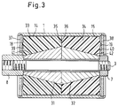
- the rubber bodies 33 and 34 are vulcanized here in the same way with their conical inner surfaces 41 and 42 onto the cores 31 and 32 and with their cylindrical outer surfaces 14 and 15 guided with play in the sleeve 1.
- the mode of operation is overall the same as in the axial bush bearing according to FIG. 1.
Landscapes
- Engineering & Computer Science (AREA)
- General Engineering & Computer Science (AREA)
- Mechanical Engineering (AREA)
- Vibration Prevention Devices (AREA)
- Support Of The Bearing (AREA)
Applications Claiming Priority (2)
| Application Number | Priority Date | Filing Date | Title |
|---|---|---|---|
| DE4033569 | 1990-10-22 | ||
| DE19904033569 DE4033569A1 (de) | 1990-03-12 | 1990-10-22 | Axial-buchsenlager |
Publications (2)
| Publication Number | Publication Date |
|---|---|
| EP0482282A1 true EP0482282A1 (fr) | 1992-04-29 |
| EP0482282B1 EP0482282B1 (fr) | 1994-01-26 |
Family
ID=6416813
Family Applications (1)
| Application Number | Title | Priority Date | Filing Date |
|---|---|---|---|
| EP91104177A Expired - Lifetime EP0482282B1 (fr) | 1990-10-22 | 1991-03-18 | Support de manchette axial |
Country Status (3)
| Country | Link |
|---|---|
| EP (1) | EP0482282B1 (fr) |
| DE (1) | DE59100946D1 (fr) |
| ES (1) | ES2048518T3 (fr) |
Cited By (7)
| Publication number | Priority date | Publication date | Assignee | Title |
|---|---|---|---|---|
| EP1357009A3 (fr) * | 2002-04-25 | 2005-05-04 | SAB WABCO GmbH | Système de freinage avec timonerie de frein pour véhicules ferroviaires |
| CN103625230A (zh) * | 2013-07-31 | 2014-03-12 | 海马轿车有限公司 | 一种底盘衬套 |
| CN104963979A (zh) * | 2015-06-30 | 2015-10-07 | 福建省博强机械发展有限公司 | 一种扭力胶芯 |
| CN110466301A (zh) * | 2019-08-13 | 2019-11-19 | 南京金龙客车制造有限公司 | 一种减振器衬套限位系统 |
| CN113386857A (zh) * | 2021-06-08 | 2021-09-14 | 河南坐骑科技有限公司 | 主动侧倾车辆转向延时装置 |
| CN115325065A (zh) * | 2022-08-19 | 2022-11-11 | 博戈橡胶塑料(株洲)有限公司 | 汽车副车架液压衬套 |
| CN119616604A (zh) * | 2025-02-13 | 2025-03-14 | 浙江机电职业技术大学 | 一种宽域运行工况下的高性能透平膨胀机的振动抑制系统 |
Families Citing this family (1)
| Publication number | Priority date | Publication date | Assignee | Title |
|---|---|---|---|---|
| DE102022105703A1 (de) * | 2022-03-10 | 2023-09-14 | Vibracoustic Se | Lageranordnung |
Citations (4)
| Publication number | Priority date | Publication date | Assignee | Title |
|---|---|---|---|---|
| GB1387726A (en) * | 1971-11-24 | 1975-03-19 | Nissan Motor | Resilient bush |
| DE3240981A1 (de) * | 1982-11-05 | 1984-05-10 | Bayerische Motoren Werke AG, 8000 München | Gummi-metall-lager |
| DE3916174A1 (de) * | 1988-05-18 | 1989-11-30 | Pirelli Sistemi Antivibranti | Elastisches verbindungselement |
| EP0384111A2 (fr) * | 1989-02-24 | 1990-08-29 | Metzeler Gimetall Ag | Support de train de roues |
-
1991
- 1991-03-18 ES ES91104177T patent/ES2048518T3/es not_active Expired - Lifetime
- 1991-03-18 EP EP91104177A patent/EP0482282B1/fr not_active Expired - Lifetime
- 1991-03-18 DE DE91104177T patent/DE59100946D1/de not_active Expired - Fee Related
Patent Citations (4)
| Publication number | Priority date | Publication date | Assignee | Title |
|---|---|---|---|---|
| GB1387726A (en) * | 1971-11-24 | 1975-03-19 | Nissan Motor | Resilient bush |
| DE3240981A1 (de) * | 1982-11-05 | 1984-05-10 | Bayerische Motoren Werke AG, 8000 München | Gummi-metall-lager |
| DE3916174A1 (de) * | 1988-05-18 | 1989-11-30 | Pirelli Sistemi Antivibranti | Elastisches verbindungselement |
| EP0384111A2 (fr) * | 1989-02-24 | 1990-08-29 | Metzeler Gimetall Ag | Support de train de roues |
Cited By (8)
| Publication number | Priority date | Publication date | Assignee | Title |
|---|---|---|---|---|
| EP1357009A3 (fr) * | 2002-04-25 | 2005-05-04 | SAB WABCO GmbH | Système de freinage avec timonerie de frein pour véhicules ferroviaires |
| CN103625230A (zh) * | 2013-07-31 | 2014-03-12 | 海马轿车有限公司 | 一种底盘衬套 |
| CN104963979A (zh) * | 2015-06-30 | 2015-10-07 | 福建省博强机械发展有限公司 | 一种扭力胶芯 |
| CN104963979B (zh) * | 2015-06-30 | 2018-05-01 | 福建省博强机械发展有限公司 | 一种扭力胶芯 |
| CN110466301A (zh) * | 2019-08-13 | 2019-11-19 | 南京金龙客车制造有限公司 | 一种减振器衬套限位系统 |
| CN113386857A (zh) * | 2021-06-08 | 2021-09-14 | 河南坐骑科技有限公司 | 主动侧倾车辆转向延时装置 |
| CN115325065A (zh) * | 2022-08-19 | 2022-11-11 | 博戈橡胶塑料(株洲)有限公司 | 汽车副车架液压衬套 |
| CN119616604A (zh) * | 2025-02-13 | 2025-03-14 | 浙江机电职业技术大学 | 一种宽域运行工况下的高性能透平膨胀机的振动抑制系统 |
Also Published As
| Publication number | Publication date |
|---|---|
| DE59100946D1 (de) | 1994-03-10 |
| EP0482282B1 (fr) | 1994-01-26 |
| ES2048518T3 (es) | 1994-03-16 |
Similar Documents
| Publication | Publication Date | Title |
|---|---|---|
| DE112013004246B4 (de) | Zylindrische Schwingungsdämpfungsvorrichtung | |
| DE69517009T2 (de) | Montageeinheit mit ungleichen radial- federsteifigkeiten | |
| DE3619626C2 (fr) | ||
| DE4033569C2 (fr) | ||
| DE102019005092B4 (de) | Schwingungstilger und Verfahren zum Herstellen eines Schwingungstilgers | |
| EP3504461B1 (fr) | Bloc de suspension | |
| EP0199240B1 (fr) | Elément de support à amortissement hydraulique pouvant être précontraint | |
| DE10142822A1 (de) | Innentilger | |
| EP0332901A2 (fr) | Manchon élastique à amortissement hydraulique | |
| DE102020126561A1 (de) | Lager und Lageranordnung | |
| DE10118229A1 (de) | Hydraulisch dämpfendes Buchsenlager | |
| EP1309463A1 (fr) | Palier a amortissement hydraulique | |
| WO2004092612A1 (fr) | Palier a douille en caoutchouc a amortissement hydraulique pour un montage vertical | |
| EP0482282B1 (fr) | Support de manchette axial | |
| DE3036418A1 (de) | Schwingungsdaempfer | |
| DE4117129C2 (fr) | ||
| EP0136700B1 (fr) | Support de moteur à amortissement hydraulique | |
| EP1181465B1 (fr) | Support elastique a comportement d'amortissement graduel | |
| EP1145941B1 (fr) | Palier de support entre la cabine conducteur et un chassis | |
| DE3111015A1 (de) | Schwingungs- und stosskraefte absorbierendes befestigungselement zur abstuetzung einer last | |
| DE3038271C2 (de) | Elastisches Lager | |
| DE19527260A1 (de) | Hydraulisch dämpfendes Motorlager | |
| EP3440379B1 (fr) | Palier hydraulique | |
| DE10312977A1 (de) | Federelement | |
| DE19961679A1 (de) | LKW-Motorlagerung |
Legal Events
| Date | Code | Title | Description |
|---|---|---|---|
| PUAI | Public reference made under article 153(3) epc to a published international application that has entered the european phase |
Free format text: ORIGINAL CODE: 0009012 |
|
| 17P | Request for examination filed |
Effective date: 19910318 |
|
| AK | Designated contracting states |
Kind code of ref document: A1 Designated state(s): DE ES FR GB IT |
|
| 17Q | First examination report despatched |
Effective date: 19930719 |
|
| GRAA | (expected) grant |
Free format text: ORIGINAL CODE: 0009210 |
|
| AK | Designated contracting states |
Kind code of ref document: B1 Designated state(s): DE ES FR GB IT |
|
| GBT | Gb: translation of ep patent filed (gb section 77(6)(a)/1977) |
Effective date: 19940201 |
|
| REF | Corresponds to: |
Ref document number: 59100946 Country of ref document: DE Date of ref document: 19940310 |
|
| REG | Reference to a national code |
Ref country code: ES Ref legal event code: FG2A Ref document number: 2048518 Country of ref document: ES Kind code of ref document: T3 |
|
| ET | Fr: translation filed | ||
| ITF | It: translation for a ep patent filed | ||
| PLBE | No opposition filed within time limit |
Free format text: ORIGINAL CODE: 0009261 |
|
| STAA | Information on the status of an ep patent application or granted ep patent |
Free format text: STATUS: NO OPPOSITION FILED WITHIN TIME LIMIT |
|
| 26N | No opposition filed | ||
| REG | Reference to a national code |
Ref country code: GB Ref legal event code: IF02 |
|
| PGFP | Annual fee paid to national office [announced via postgrant information from national office to epo] |
Ref country code: GB Payment date: 20020222 Year of fee payment: 12 |
|
| PG25 | Lapsed in a contracting state [announced via postgrant information from national office to epo] |
Ref country code: GB Free format text: LAPSE BECAUSE OF NON-PAYMENT OF DUE FEES Effective date: 20030318 |
|
| GBPC | Gb: european patent ceased through non-payment of renewal fee |
Effective date: 20030318 |
|
| PG25 | Lapsed in a contracting state [announced via postgrant information from national office to epo] |
Ref country code: IT Free format text: LAPSE BECAUSE OF NON-PAYMENT OF DUE FEES;WARNING: LAPSES OF ITALIAN PATENTS WITH EFFECTIVE DATE BEFORE 2007 MAY HAVE OCCURRED AT ANY TIME BEFORE 2007. THE CORRECT EFFECTIVE DATE MAY BE DIFFERENT FROM THE ONE RECORDED. Effective date: 20050318 |
|
| PGFP | Annual fee paid to national office [announced via postgrant information from national office to epo] |
Ref country code: FR Payment date: 20050318 Year of fee payment: 15 |
|
| PGFP | Annual fee paid to national office [announced via postgrant information from national office to epo] |
Ref country code: ES Payment date: 20050413 Year of fee payment: 15 |
|
| PG25 | Lapsed in a contracting state [announced via postgrant information from national office to epo] |
Ref country code: ES Free format text: LAPSE BECAUSE OF NON-PAYMENT OF DUE FEES Effective date: 20060321 |
|
| REG | Reference to a national code |
Ref country code: FR Ref legal event code: ST Effective date: 20061130 |
|
| PGFP | Annual fee paid to national office [announced via postgrant information from national office to epo] |
Ref country code: DE Payment date: 20070411 Year of fee payment: 17 |
|
| REG | Reference to a national code |
Ref country code: ES Ref legal event code: FD2A Effective date: 20060321 |
|
| PG25 | Lapsed in a contracting state [announced via postgrant information from national office to epo] |
Ref country code: FR Free format text: LAPSE BECAUSE OF NON-PAYMENT OF DUE FEES Effective date: 20060331 |
|
| PG25 | Lapsed in a contracting state [announced via postgrant information from national office to epo] |
Ref country code: DE Free format text: LAPSE BECAUSE OF NON-PAYMENT OF DUE FEES Effective date: 20081001 |