EP0482338B1 - Batterie de fours à coke sans récupération et procédé pour son opération - Google Patents
Batterie de fours à coke sans récupération et procédé pour son opération Download PDFInfo
- Publication number
- EP0482338B1 EP0482338B1 EP91115479A EP91115479A EP0482338B1 EP 0482338 B1 EP0482338 B1 EP 0482338B1 EP 91115479 A EP91115479 A EP 91115479A EP 91115479 A EP91115479 A EP 91115479A EP 0482338 B1 EP0482338 B1 EP 0482338B1
- Authority
- EP
- European Patent Office
- Prior art keywords
- ovens
- draft
- stack
- valve
- oven
- Prior art date
- Legal status (The legal status is an assumption and is not a legal conclusion. Google has not performed a legal analysis and makes no representation as to the accuracy of the status listed.)
- Expired - Lifetime
Links
- 239000000571 coke Substances 0.000 title claims description 18
- 238000000034 method Methods 0.000 title claims description 11
- 238000004939 coking Methods 0.000 claims description 38
- 239000007789 gas Substances 0.000 claims description 16
- 230000001105 regulatory effect Effects 0.000 claims description 15
- 239000012530 fluid Substances 0.000 claims description 8
- 206010022000 influenza Diseases 0.000 claims description 8
- 230000001276 controlling effect Effects 0.000 claims description 6
- 239000002184 metal Substances 0.000 claims description 5
- 239000003546 flue gas Substances 0.000 claims description 4
- 230000008602 contraction Effects 0.000 claims description 2
- 238000002485 combustion reaction Methods 0.000 description 17
- 239000003245 coal Substances 0.000 description 10
- 238000009434 installation Methods 0.000 description 3
- 239000002918 waste heat Substances 0.000 description 3
- 239000006227 byproduct Substances 0.000 description 2
- 238000010276 construction Methods 0.000 description 2
- 238000001816 cooling Methods 0.000 description 2
- 239000000203 mixture Substances 0.000 description 2
- 239000000047 product Substances 0.000 description 2
- 238000007789 sealing Methods 0.000 description 2
- 239000002699 waste material Substances 0.000 description 2
- 229910000831 Steel Inorganic materials 0.000 description 1
- 239000011449 brick Substances 0.000 description 1
- 238000004891 communication Methods 0.000 description 1
- 238000004821 distillation Methods 0.000 description 1
- 239000012467 final product Substances 0.000 description 1
- 238000010438 heat treatment Methods 0.000 description 1
- 235000003642 hunger Nutrition 0.000 description 1
- 230000000284 resting effect Effects 0.000 description 1
- 239000010959 steel Substances 0.000 description 1
- 239000000126 substance Substances 0.000 description 1
- 230000007704 transition Effects 0.000 description 1
- 238000003466 welding Methods 0.000 description 1
Images


Classifications
-
- C—CHEMISTRY; METALLURGY
- C10—PETROLEUM, GAS OR COKE INDUSTRIES; TECHNICAL GASES CONTAINING CARBON MONOXIDE; FUELS; LUBRICANTS; PEAT
- C10B—DESTRUCTIVE DISTILLATION OF CARBONACEOUS MATERIALS FOR PRODUCTION OF GAS, COKE, TAR, OR SIMILAR MATERIALS
- C10B21/00—Heating of coke ovens with combustible gases
-
- C—CHEMISTRY; METALLURGY
- C10—PETROLEUM, GAS OR COKE INDUSTRIES; TECHNICAL GASES CONTAINING CARBON MONOXIDE; FUELS; LUBRICANTS; PEAT
- C10B—DESTRUCTIVE DISTILLATION OF CARBONACEOUS MATERIALS FOR PRODUCTION OF GAS, COKE, TAR, OR SIMILAR MATERIALS
- C10B27/00—Arrangements for withdrawal of the distillation gases
- C10B27/06—Conduit details, e.g. valves
-
- C—CHEMISTRY; METALLURGY
- C10—PETROLEUM, GAS OR COKE INDUSTRIES; TECHNICAL GASES CONTAINING CARBON MONOXIDE; FUELS; LUBRICANTS; PEAT
- C10B—DESTRUCTIVE DISTILLATION OF CARBONACEOUS MATERIALS FOR PRODUCTION OF GAS, COKE, TAR, OR SIMILAR MATERIALS
- C10B15/00—Other coke ovens
- C10B15/02—Other coke ovens with floor heating
Definitions
- This invention relates to an improved draft control system and a method for controlling the draft in combination with a nonrecovery coking of coal according to claim 1 and 10 respectively.
- a plurality of sole flue-heated nonrecovery coke ovens constructed in side-by-side relation in a battery and having their chimney uptake outlets connected to a common combustion tunnel extending longitudinally of and above the battery and connected to stacks at spaced intervals along its length.
- No means is provided for regulating the draft to the individual ovens to enable control of the coking rate in the individual ovens.
- the sole flue system from opposite ends of adjacent ovens are connected to each chimney for connection to the elongated waste heat tunnel.
- a manually adjustable damper valve is provided in each such chimney to assure complete incineration of unburned combustibles discharged from the ovens.
- This valve however is not intended for controlling the draft to the individual ovens to thereby control the coking rate therein.
- the provided refractory valve plate is intended only to seal the gas flow passage from the sole flues into the waste heat tunnel to avoid axcessive cooling when the ovens are not charged.
- Such ovens may have a coking chamber of up to 15,25 m (50 feet) in length and 3,66 m (12 feet) in width, and may be filled to a depth of up to 1,525 m (5 feet) or more with green coal at the beginning of a forty-eight hour coking cycle.
- Normally eight or more adjacent ovens are connected through a common combustion tunnel to a single stack, and no means other than varying the amount of combustion air admitted through inlets in the oven doors, the sole flues, and the common tunnel, are provided for varying the draft to the respective ovens.
- Another object of the invention is to provide a draft control system in combination with a coking installation for controlling ad regulating the draft supplied to the individual coking ovens in a battery of ovens connected to a common stack for the high speed coking of coal at a more uniform coking rate throughout the ovens of the battery, which enables an increased yield of high quality coke from a charge of coal.
- the object of the invention is solved according to features of claim 1 and of claim 9, respectively.
- An important feature resides in providing a plurality of sole flue heated nonrecovery coke ovens constructed in side-by-side relation in a battery with two separate sole flue systems located one under each end portion of the oven. Chimney uptakes extending through the walls between adjacent ovens have their outlets connected through a duct system including draft control valve means operable to regulate the flow of hot flue gases through the uptakes from each sole flue system.
- the draft from the sole flues to that oven may be adjusted to thereby regulate the temperature and consequently the coking rate independently of the other ovens in the bottom.
- the duct system connected to the uptakes of each sole flue system is connected, above the ovens, to an elongated common combustion tunnel extending above and transversely of the ovens in the battery and a stack connected to the combustion tunnel extends upwardly therefrom to provide a draft to all of the ovens in the battery.
- the term "battery” is used herein to designate the plurality of ovens connected to a common combustion tunnel, although a plurality of such "batteries" may be constructed as a unit.
- a single battery may consist of nine (9) ovens connected to each common tunnel and stack, with a plurality of such batteries constructed as a single inline unit, in which case the term “battery” may also be used in the industry to refer to complete installation.
- the stack for each individual battery of ovens is equipped, at its top, with a butterfly type stack draft control valve or damper assembly with power means operable to move the valve between the fully open position providing substantially unobstructed gas flow from the stack to the fully closed position substantially sealing the top of the stack.
- the position of the stack draft control valve is normally maintained at or near the full open position, but the valve may be adjusted to restrict the flow of gas from the stack to provide the desired draft in the common combustion tunnel. Again, regulating the stack draft will influence the temperature and consequently the coking rate.
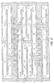
- a coal coking battery 10 embodying the present invention is illustrated as including a plurality of ovens 12 constructed in side-by-side relation with adjacent ovens having common sidewalls 14.
- the ovens 12 have an elongated coking chamber 16 defined by the opposed vertically extending sidewalls 14, a generally arcuate roof 18 supported on the sidewalls, and a horizontal floor 20 which supports the charge of coal to be coked.
- the ovens are constructed with open ends which are closed during the coking cycle by substantially identical removable doors 22.
- Doors 22 preferably are of welded steel construction having a castable refractory lining, with a plurality of adjustable air inlets 24 formed in each door.
- the floor 20 is supported by the sidewalls 14 and by a plurality of parallel intermediate refractory brick walls 30 which cooperate to define a system of elongated sole flues described below.
- a plurality of vertically extending downcomers, or channels, 42 are formed in the sidewalls 14, with the downcomers each having an inlet 44 communicating with the top or crown portion of the associated coking chamber 16 and an outlet 46 leading into a sole flue tunnel 32 adjacent the sidewall 14.
- a plurality of chimneys, or uptakes 48 are also formed in each of the common sidewalls 14, with each uptake having an inlet 50 communicating with an adjacent sole flue tunnel 32. The uptakes extend upwardly through the walls 14 for communication with a chimney extension or duct system to be described more fully hereinbelow.
- each sidewall 14 is formed with six downcomers and four uptakes, with the six downcomers being located in equally spaced relation, three on either side of the longitudinal centerline of the battery and preferably with the outboard uptake spaced from the longitudinal centerline a distance no more than about 25 percent, and preferably less than about 20 percent, of the total length of the individual oven.
- the total length of the oven is 13,2 m (46 feet 8 inches) and the distance from the longitudinal centerline of the battery to the outer wall of the outer downcomer is 3,2 m (8 feet 3 inches).
- the uptakes 48 are located in the wall 14 outboard of the downcomers, with the outboard uptake preferably being spaced from the end of sidewall 14 a distance of at least about 20 percent and preferably about 25 percent of the total length of the oven.
- a series of divider walls 52 extend perpendicular to the intermediate walls 30 and divide the respective sole flues 32 into sections isolated from one another on opposite end portions of the oven. Adjacent sole flue sections are interconnected at alternate ends thereof by crossover openings 54 in the walls 30 to provide a continuous back-and-forth flow pattern traversing the width of the oven at one end thereof, and the adjacent sole flue sections at the other end are interconnected at the opposite ends by similar crossovers 54 to provide a continuous back-and-forth gas flow pattern across the other end of the oven.
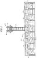
- Duct 56 consists of an upwardly extending transition segment 58 in which the gases from the two uptakes are combined, an elbow 60, and a horizontally extending segment 62 connected to a common elongated waste heat or combustion tunnel 64 extending transversely of and above the roofs of the ovens in the battery.
- the duct system 56 is constructed of a refractory lined generally rectangular metal conduit, and a draft control valve is connected in horizontal section 62 for regulating the draft applied through the connected sole flue system to the associated oven chamber 16.
- the common tunnel 64 extends across the full length of battery 10 (which in the embodiment illustrated, consists of nine ovens), and a single common stack 68 connected to the central portion of the combustion tunnel extends upwardly therefrom to apply a draft to the common combustion tunnel and thereby to the sole flue systems beneath all ovens in the battery.
- a separate duct system 56 is provided to connect each sole flue system to the common tunnel 64 and, since these duct systems are identical, only one system will be described in detail, it being understood that the description applies to all such systems in the installation.
- the draft control valve comprises a refractory lined valve body 70 connected in section 62, with the valve body having a rectangular opening 72 in its bottom wall for receiving a refractory valve plate or damper 74 supported for vertical sliding movement into and out of the valve body between a fully raised position substantially completely closing the gas flow path through the duct system and a lowered position in which the gas flow path is substantially unobstructed.
- the refractory plate 74 is mounted on a horizontally extending metal base plate 76 which projects laterally outward from each side of the valve body 70, and a fluid cylinder 78 is provided to move the valve plate in the vertical direction.
- Fluid cylinder 78 is mounted in fixed position on a structural beam 80 supported by columns 81 on top of wall 14, and has its rod end pivotally connected through pin 82 to base plate 76 to move the valve plate 74 as described.
- a pair of vertically extending rectangular tubular members 84 are welded in spaced relation to one another on each outer vertical sidewall of the valve body 70 to define guide channels receiving a pair of guide posts 88 mounted on and projecting vertically upward from the opposed outwardly projecting end portions of base plate 76.
- Posts 88 are guided for vertical sliding movement in the guide channels to retain the refractory valve plate 74 in accurate alignment with the rectangular opening 72 through the bottom of the refractory lined valve body 70.
- a plurality of guide rollers 90 are mounted on and project outwardly from opposed side faces of posts 88 in position to engage the outwardly directed surface of the rectangular tubes 84 to accurately maintain the valve plates 74 and base plate 76 aligned transversely of the opening 72.
- the pin connection 82 is constructed with sufficient clearance to permit limited movement of the base plate 76 and of valve plate 74 relative to the fluid cylinder 78 to accommodate limited movement of the valve body as a result of thermal expansion and contraction of the duct system during operation.
- one of the guide posts 88 carries a rack 94 which engages a pinion 96 supported on the valve body 70 for rotation by vertical movement of the rack with the valve plate.
- Pinion 96 is connected to a position indicator switch or potentiometer 98 which provides a signal to an operator's pulpit (not shown) continuously indicating the position of the draft control valve. This enables the operator to accurately position the fluid cylinder of each draft control valve from a common control station to independently control the draft in the respective ovens and thereby maintain a uniform coking rate throughout the battery.
- Suitable sensors including temperature sensors in the crown of the oven or the sole flue, and pressure sensors in the oven crown, sole flues, or uptakes may be used to determine the desired position of the draft control valves, and signals from these sensors in combination with the signal from the valve position sensors 98, may be fed to a computer or process controller to automatically maintain continuous control over the operation of the entire battery.
- stack 68 is equipped with a draft control damper valve assembly 100 made up of two substantially identical subassemblies 102, 104 mounted on diametrically opposed sides of the stack adjacent its top.
- Each subassembly includes a semicircular refractory valve plate 106 rigidly mounted on a support frame 108 supported for pivotal movement about a horizontally extending shaft 110.
- Shaft 110 is supported by a pair of journal bearings 112 on outwardly projecting bracket members 114 rigidly mounted, as by welding, on the metallic outer shell of the refractory lined stack 68.
- the two valve plate members 106 cooperate to form an inverted lid resting upon and sealing the open top of the stack 68.
- Structural frames 108 include a pair of laterally spaced arms 116 projecting outwardly from shaft 110 in the direction opposite to plate 106, and a heavy slab 118 of concrete or the like is mounted on arms 116 to counterbalance the weight of the valve plate 106.
- a fluid cylinder 120 has its cylinder end pivotally connected to a bracket 122 on stack 68 and its rod end pivotally connected through bracket 124 to the arms 116. As shown in Fig. 9, fluid cylinder 120 may be employed to pivot the arms 116 in a direction to rotate the frame 108 about shaft 110 to move the valve plates 106 between the closed position shown in broken lines to the fully open position shown in full lines.
- the draft control damper assembly In the closed position, the draft control damper assembly effectively seals the top of the stack, cutting off all draft to the ovens. In the fully opened position, plates 106 offer essentially no resistance to gas flow, enabling these stacks to provide maximum draft to the ovens. It is understood, of course, that the coke oven battery cannot operate to produce coke when the stack is closed and the draft control damper valve assembly is only fully closed when no oven in the battery has a charge of coke therein. Closing the damper valve assembly prevents the stack from drawing cooling air through the ovens when the ovens are not in use to produce coke, thereby preserving heat in the ovens for the start-up of the next coking cycle.
- the stack draft control valve assembly 100 may be positioned to act as a damper, restricting the draft applied by the stack to the common tunnel and thereby to all the ovens in the battery.
- the overall coking rate in the battery may be influenced while at the same time, adjustment of the chimney uptake draft control valve 66 permits adjustment of the draft to the individual ovens as required to produce a more uniform coking rate throughout the battery.
- the coking characteristics of the coal charge will, to some extent, determine the draft required to the ovens to maintain the desired burning rate of the coke gas and distillation products.
- the coal mix employed is consistent or uniform, it may be possible to provide a fixed or standard open setting for the stack draft control valve and provide the desired control by adjusting the uptake control valve only during the coking cycle. This standard open setting for the stack draft valve may then be adjusted when the mix of coal making up the charge is changed, or when other conditions make it impractical to provide the necessary control by use of the uptake draft control only.
Landscapes
- Chemical & Material Sciences (AREA)
- Engineering & Computer Science (AREA)
- Oil, Petroleum & Natural Gas (AREA)
- Materials Engineering (AREA)
- Organic Chemistry (AREA)
- Chemical Kinetics & Catalysis (AREA)
- General Chemical & Material Sciences (AREA)
- Combustion & Propulsion (AREA)
- Coke Industry (AREA)
Claims (12)
- Système de commande de tirage combiné à une batterie (10) de fours à coke sans récupération du type comportant plusieurs fours à coke allongés (12) ayant des extrémités normalement fermées par des portes amovibles (22) et construits côte à côte, des fours adjacents étant séparés par des parois latérales communes (14), deux systèmes séparés de carneaux de sol (32) s'étendant chacun en dessous d'une partie d'extrémité opposée de chaque four, plusieurs carneaux de retour (42) situés dans chacune des parois latérales communes (14) reliant la partie supérieure de chaque four adjacent à l'un des systèmes (32) formant carneaux de sole situé en dessous de ce four, plusieurs évacuations (4) agencées dans chaque paroi latérale commune (14) comportant au moins une évacuation reliée à l'un des systèmes (32) formant carneaux de sole situé en dessous de chaque four adjacent (12), un tunnel d'échappement (64) commun allongé s'étendant au-dessus des fours (12) de la batterie (10) et transversalement à ceux-ci, une cuve (68) reliée au tunnel d'échappement (64) et s'étendant vers le haut à partir de celui-ci, et des moyens (56) formant conduit isolé reliant le tunnel d'échappement (64) aux évacuations (48) pour fournir un trajet d'écoulement de gaz continu à partir de chaque four (12) vers l'atmosphère, à travers les carneaux de retour (42), les évacuations (48) des systèmes (32) formant carneaux de sole, les moyens formant conduit isolé, le tunnel d'échappement et les cuves, caractérisé en ce que ledit système de commande de tirage comporte :
des moyens (56) formant conduit isolé séparé relié entre ledit tunnel d'échappement (64) et ladite au moins une évacuation (48) reliée à chaque système (32) formant carneau de sole, chacun desdits moyens formant conduit isolé comportant un conduit métallique revêtu de matériau réfractaire espacé au-dessus desdits fours (12),
des moyens formant vanne de régulation de tirage reliée à chaque moyen (56) formant conduit isolé, chaque moyen formant vanne de régulation de tirage comportant un corps de vanne (70) revêtu de matériau réfractaire ayant une ouverture (72) qui y est située dirigée vers le bas, un élément (74) formant vanne réfractaire mobile montée pour se déplacer verticalement à travers ladite ouverture dirigée vers le bas (72), et
des premiers moyens de puissance (78) reliés à ladite plaque (74) de vanne réfractaire et pouvant être actionnés de manière sélective pour positionner ladite plaque (74) de vanne pour réguler l'écoulement des gaz brûlés chauds provenant du système (32) formant carneau de sole relié vers le tunnel d'échappement (64) pour commander ainsi de manière indépendante la vitesse de cokéfaction dans les fours respectifs. - Dispositif selon la revendication 1, dans lequel lesdits premiers moyens de puissance comportent un cylindre (78) actionné par un fluide, supporté de manière indépendante desdits moyens formant conduit isolé et relié à ladite plaque (74) de vanne réfractaire, ledit cylindre (78) actionné par un fluide pouvant être actionné pour élever et abaisser ladite plaque (74) de vanne réfractaire à travers ladite ouverture (72) existant dans ledit corps (70) de vanne pour commander l'écoulement du gaz à travers le conduit métallique (60) et comportant en outre des moyens de détection (98) pour détecter en continu la position de chacune desdites plaques (74) de vanne réfractaire.
- Dispositif selon la revendication 2, dans lequel lesdits moyens formant vanne de régulation de tirage comportent en outre des moyens de guidage (88) montés sur la partie extérieure dudit corps (70) de vanne et mobiles avec celui-ci lors d'une dilatation et d'une contraction thermiques dudit conduit métallique recouvert de matériau réfractaire pour maintenir ladite plaque (74) de vanne réfractaire alignée avec ledit corps (70) de vanne.
- Dispositif selon la revendication 3, dans lequel lesdites évacuations (48) sont situées entre les carneaux de retour (42) et les extrémités des fours respectifs (12).
- Dispositif selon la revendication 4, dans lequel la distance existant entre les extrémités ouvertes desdits fours allongés (12) et le carneau de retour le plus proche (42) est au moins environ 20% de la longueur du four.
- Dispositif selon la revendication 4, dans lequel la distance existant entre les extrémités ouvertes desdits fours allongés (12) et le carneau de retour le plus proche (42) est au moins environ 25% de la longueur du four.
- Dispositif selon la revendication 1, comportant en outre des moyens (100) de régulation de tirage de cuve situés sur ladite cuve (68) pour limiter l'écoulement des gaz de cuve chauds vers l'atmosphère, lesdits moyens de régulation de tirage de cuve comportant des moyens (106) formant amortisseur et des seconds moyens de puissance (120) pouvant être actionnés pour ouvrir et fermer lesdits moyens formant amortisseur et ainsi commander le tirage appliqué par la cuve (68) vers le tunnel d'échappement (64), de sorte qu'un tirage uniforme commandé soit appliqué par la cuve à travers le tunnel d'échappement (64) pour tous lesdits moyens formant conduit isolé situés dans la batterie, et l'écoulement des gaz brûlés chauds provenant des systèmes (32) formant carneaux de sole est régulé par lesdits moyens (100) formant vanne de régulation de tirage pour commander ledit tirage appliqué à chaque four (12) de manière indépendante et par conséquent commander de manière indépendante le taux de cokéfaction dans les fours respectifs.
- Dispositif selon la revendication 1, dans lequel lesdits moyens amortisseurs comportent une paire d'éléments (106) formant vannes montées pour limiter le mouvement pivotant autour d'un axe parallèle écarté (110) situé de chaque côté de la cuve (68) au niveau de la partie supérieure ouverte de celle-ci, et lesdits seconds moyens de puissance (120) comportent des moyens pour mettre en rotation lesdits éléments (106) formant vannes autour de leurs axes de pivotement respectifs (110) à partir d'une position de manière générale horizontale fermant à peu près la cuve (68) vers une position relevée fournissant une limitation minimale de l'écoulement à travers la cuve.
- Dispositif selon la revendication 8, comportant en outre des moyens de détection pour détecter en continu la position de chaque plaque (106) de vanne réfractaire.
- Procédé de commande du tirage d'une batterie de fours à coke sans récupération selon l'une quelconque des revendications 1 à 9, caractérisé en ce qu'il comporte les étapes consistant à :
fournir un conduit isolé séparé relié entre ledit tunnel d'échappement et ladite au moins une évacuation reliée à chaque système formant carneau de sole,
fournir une vanne de régulation de tirage reliée à chaque conduit isolé, et
régler de manière sélective la position desdites vannes de régulation de tirage pour ainsi réguler l'écoulement des gaz brûlés chauds provenant du système formant carneau de sole relié vers le tunnel d'échappement et commander la vitesse de cokéfaction dans les fours. - Procédé selon la revendication 10, comportant en outre l'étape consistant à détecter la température existant à l'intérieur de chaque four à coke, lesdites vannes de régulation de tirage étant réglées en réponse à ladite température détectée.
- Procédé selon la revendication 11, comportant en outre l'étape consistant à fournir une vanne d'amortisseur située sur la cuve pour limiter l'écoulement des gaz chauds de cuve vers l'atmosphère, et réguler la position de la vanne d'amortisseur pour commander ainsi le tirage appliqué par la cuve vers le tunnel d'échappement.
Applications Claiming Priority (2)
| Application Number | Priority Date | Filing Date | Title |
|---|---|---|---|
| US587742 | 1990-09-25 | ||
| US07/587,742 US5114542A (en) | 1990-09-25 | 1990-09-25 | Nonrecovery coke oven battery and method of operation |
Publications (2)
| Publication Number | Publication Date |
|---|---|
| EP0482338A1 EP0482338A1 (fr) | 1992-04-29 |
| EP0482338B1 true EP0482338B1 (fr) | 1994-12-28 |
Family
ID=24351020
Family Applications (1)
| Application Number | Title | Priority Date | Filing Date |
|---|---|---|---|
| EP91115479A Expired - Lifetime EP0482338B1 (fr) | 1990-09-25 | 1991-09-12 | Batterie de fours à coke sans récupération et procédé pour son opération |
Country Status (10)
| Country | Link |
|---|---|
| US (2) | US5114542A (fr) |
| EP (1) | EP0482338B1 (fr) |
| JP (1) | JP3027640B2 (fr) |
| KR (1) | KR100191339B1 (fr) |
| AU (1) | AU641044B2 (fr) |
| BR (1) | BR9104095A (fr) |
| CA (1) | CA2052177C (fr) |
| DE (1) | DE69106312T2 (fr) |
| MX (1) | MX9101216A (fr) |
| PL (1) | PL165840B1 (fr) |
Families Citing this family (77)
| Publication number | Priority date | Publication date | Assignee | Title |
|---|---|---|---|---|
| US5114542A (en) * | 1990-09-25 | 1992-05-19 | Jewell Coal And Coke Company | Nonrecovery coke oven battery and method of operation |
| US5447606A (en) * | 1993-05-12 | 1995-09-05 | Sun Coal Company | Method of and apparatus for capturing coke oven charging emissions |
| IT1276116B1 (it) * | 1995-11-10 | 1997-10-24 | O E T Calusco S R L | Procedimento ed impianto per la produzione di carbone vegetale mediante pirolisi di prodotti legnosi o biomasse vegetali in genere |
| DE19729032C1 (de) * | 1997-07-08 | 1999-02-11 | Dmt Gmbh | Vorrichtung zum Abdichten einer Planiertüröffnung einer Koksofenkammer |
| US5928476A (en) * | 1997-08-19 | 1999-07-27 | Sun Coal Company | Nonrecovery coke oven door |
| US6187148B1 (en) | 1999-03-01 | 2001-02-13 | Pennsylvania Coke Technology, Inc. | Downcomer valve for non-recovery coke oven |
| KR100502827B1 (ko) * | 2000-06-09 | 2005-07-25 | 주식회사 포스코 | 코크스 오븐내의 폐가스 배출장치 |
| US6596128B2 (en) * | 2001-02-14 | 2003-07-22 | Sun Coke Company | Coke oven flue gas sharing |
| KR100957917B1 (ko) | 2003-06-10 | 2010-05-13 | 주식회사 포스코 | 코크스오븐의 미니상승관 개폐장치 |
| US7150627B2 (en) * | 2005-04-30 | 2006-12-19 | Siddhartha Gaur | Transported material heating with controlled atmosphere |
| DE102005055483A1 (de) * | 2005-11-18 | 2007-05-31 | Uhde Gmbh | Zentral gesteuertes Koksofenbelüftungssystem für Primär- und Sekundärluft |
| DE102006004669A1 (de) * | 2006-01-31 | 2007-08-09 | Uhde Gmbh | Koksofen mit optimierter Steuerung und Verfahren zur Steuerung |
| DE102006005189A1 (de) * | 2006-02-02 | 2007-08-09 | Uhde Gmbh | Verfahren und Vorrichtung zur Verkokung von Kohle mit hohem Flüchtigengehalt |
| US20070234974A1 (en) * | 2006-04-10 | 2007-10-11 | The Cust-O-Fab Companies, Llc | Fired heater and flue gas tunnel therefor |
| DE202006009985U1 (de) * | 2006-06-06 | 2006-10-12 | Uhde Gmbh | Bodenkonstruktion für horizontale Koksöfen |
| DE102006045056A1 (de) * | 2006-09-21 | 2008-03-27 | Uhde Gmbh | Koksofen |
| DE102006045067A1 (de) | 2006-09-21 | 2008-04-03 | Uhde Gmbh | Koksofen mit verbesserten Heizeigenschaften |
| DE102007042502B4 (de) | 2007-09-07 | 2012-12-06 | Uhde Gmbh | Vorrichtung zur Zuführung von Verbrennungsluft oder verkokungsbeeinflussenden Gasen in den oberen Bereich von Verkokungsöfen |
| DE102007057410B3 (de) * | 2007-11-27 | 2009-07-30 | Uhde Gmbh | Mechanismus und Verfahren zur automatisierbaren Verriegelung von Türen, Türkörpern oder Türrahmen horizontaler Koksofenkammern |
| DE102007058473B4 (de) * | 2007-12-04 | 2009-11-26 | Uhde Gmbh | Verfahren und Vorrichtung zum Verschließen eines Koksofens, der durch eine horizontal gerichtete, vorder- und hinterseitige Ofenöffnung beladen oder für die Verkokung vorbereitet wird |
| US8287696B2 (en) * | 2008-09-05 | 2012-10-16 | Purdue Research Foundation | Multipurpose coke plant for synthetic fuel production |
| DE102008050599B3 (de) * | 2008-10-09 | 2010-07-29 | Uhde Gmbh | Vorrichtung und Verfahren zur Verteilung von Primärluft in Koksöfen |
| US7998316B2 (en) | 2009-03-17 | 2011-08-16 | Suncoke Technology And Development Corp. | Flat push coke wet quenching apparatus and process |
| DE102009015270A1 (de) * | 2009-04-01 | 2010-10-14 | Uhde Gmbh | Verkokungsanlage mit Abgasrückführung |
| DE102010010184A1 (de) | 2010-03-03 | 2011-09-08 | Uhde Gmbh | Verfahren und Vorrichtung zur Verkokung von Kohlemischungen mit hohen Treib-druckeigenschaften in einem "Non-Recovery"- oder "Heat-Recovery"-Koksofen |
| US9200225B2 (en) | 2010-08-03 | 2015-12-01 | Suncoke Technology And Development Llc. | Method and apparatus for compacting coal for a coal coking process |
| DE102011120489A1 (de) | 2011-12-08 | 2013-06-13 | Thyssenkrupp Uhde Gmbh | Verfahren und Vorrichtung zum Beschicken von "Heat-Recovery"- oder "Non-Recovery"-Koksöfen mit kompaktierter Kohle über einer Setzbodentrennschicht |
| US9310132B1 (en) | 2012-02-08 | 2016-04-12 | Carbonyx, Inc. | Replaceable insulation roof for industrial oven |
| DE102012002963A1 (de) | 2012-02-16 | 2013-08-22 | Thyssenkrupp Uhde Gmbh | Verfahren und Vorrichtung zur flächenoptimierten Zuführung von Verbrennungsluft in den Primärheizraum einer Koksofenkammer des Typs "Non-Recovery" oder "Heat-Recovery" |
| DE102012008936B3 (de) | 2012-05-08 | 2013-11-14 | Thyssenkrupp Uhde Gmbh | Planierkasten einer Koksofenkammer mit einem darin enthaltenen feuerfesten Formkörper als Abstreifkontur, Planierstange und Verfahren zum Planieren einer Kohleschüttung in einer befüllten Koksofenkammer |
| DE102012014741A1 (de) | 2012-07-26 | 2014-05-15 | Thyssenkrupp Uhde Gmbh | Vorrichtung und Verfahren zur gerichteten Einleitung von Verbrennungsluft in die Sekundärheizräume eines Koksofens vom Typ "Heat-Recovery" |
| EP2879777B1 (fr) | 2012-07-31 | 2019-05-29 | SunCoke Technology and Development LLC | Procédés de prise en charge des émissions résultant du traitement du charbon et systèmes et dispositifs associés |
| US9243186B2 (en) * | 2012-08-17 | 2016-01-26 | Suncoke Technology And Development Llc. | Coke plant including exhaust gas sharing |
| US9359554B2 (en) | 2012-08-17 | 2016-06-07 | Suncoke Technology And Development Llc | Automatic draft control system for coke plants |
| US9249357B2 (en) * | 2012-08-17 | 2016-02-02 | Suncoke Technology And Development Llc. | Method and apparatus for volatile matter sharing in stamp-charged coke ovens |
| US9169439B2 (en) | 2012-08-29 | 2015-10-27 | Suncoke Technology And Development Llc | Method and apparatus for testing coal coking properties |
| PL2898048T3 (pl) * | 2012-09-21 | 2020-11-16 | Suncoke Technology And Development Llc | Przetwarzanie w piecu koksowniczym o zmniejszonej wydajności z dzieleniem gazu zapewniające wydłużony cykl procesu |
| DE102012019746B3 (de) | 2012-10-09 | 2013-12-24 | Thyssenkrupp Uhde Gmbh | Vorrichtung und Verfahren zur Erzeugung einer Mehrzahl an Dampf- oder Heißwasserströmen in einer Koksofenbank |
| US9273249B2 (en) * | 2012-12-28 | 2016-03-01 | Suncoke Technology And Development Llc. | Systems and methods for controlling air distribution in a coke oven |
| US10047295B2 (en) | 2012-12-28 | 2018-08-14 | Suncoke Technology And Development Llc | Non-perpendicular connections between coke oven uptakes and a hot common tunnel, and associated systems and methods |
| US9476547B2 (en) | 2012-12-28 | 2016-10-25 | Suncoke Technology And Development Llc | Exhaust flow modifier, duct intersection incorporating the same, and methods therefor |
| WO2014105065A1 (fr) | 2012-12-28 | 2014-07-03 | Suncoke Technology And Development Llc. | Couvercles de colonne de ventilation et systèmes et procédés associés |
| WO2014105062A1 (fr) | 2012-12-28 | 2014-07-03 | Suncoke Technology And Development Llc. | Systèmes et procédés de suppression du mercure des émissions |
| US9238778B2 (en) | 2012-12-28 | 2016-01-19 | Suncoke Technology And Development Llc. | Systems and methods for improving quenched coke recovery |
| US10883051B2 (en) | 2012-12-28 | 2021-01-05 | Suncoke Technology And Development Llc | Methods and systems for improved coke quenching |
| US10760002B2 (en) | 2012-12-28 | 2020-09-01 | Suncoke Technology And Development Llc | Systems and methods for maintaining a hot car in a coke plant |
| US9193915B2 (en) | 2013-03-14 | 2015-11-24 | Suncoke Technology And Development Llc. | Horizontal heat recovery coke ovens having monolith crowns |
| PL2970768T3 (pl) * | 2013-03-14 | 2022-01-17 | Suncoke Technology And Development Llc | System koksowniczy z nieprostopadłymi połączeniami między przewodami wznoszącymi pieca koksowniczego a gorącym wspólnym tunelem oraz sposób zmniejszania strat ciągu |
| US9273250B2 (en) | 2013-03-15 | 2016-03-01 | Suncoke Technology And Development Llc. | Methods and systems for improved quench tower design |
| DE102013112036A1 (de) | 2013-10-31 | 2015-04-30 | Thyssenkrupp Ag | Verkokungsanlage zum Verkoken von Kohle und Verfahren zur Optimierung der Verkokungsbedingungen |
| BR112016015475B1 (pt) | 2013-12-31 | 2021-02-17 | Suncoke Technology And Development Llc | método de descarbonização de um forno de coque de depósitos de coque e sistema de coqueificação |
| US10526541B2 (en) | 2014-06-30 | 2020-01-07 | Suncoke Technology And Development Llc | Horizontal heat recovery coke ovens having monolith crowns |
| PL3186340T3 (pl) * | 2014-08-28 | 2021-04-19 | Suncoke Technology And Development Llc | Sposób i system do optymalizacji i wydajności instalacji koksowniczej |
| RU2702546C2 (ru) | 2014-09-15 | 2019-10-08 | САНКОУК ТЕКНОЛОДЖИ ЭНД ДИВЕЛОПМЕНТ ЭлЭлСи | Коксовые печи, имеющие конструкцию из монолитных компонентов |
| DE102014221150B3 (de) * | 2014-10-17 | 2016-03-17 | Thyssenkrupp Ag | Koksofen mit verbesserter Abgasführung in den Sekundärheizräumen und ein Verfahren zur Verkokung von Kohle sowie die Verwendung des Koksofens |
| WO2016109704A1 (fr) | 2014-12-31 | 2016-07-07 | Suncoke Technology And Development Llc | Lits multi-modaux de matière à cokéfier |
| EP3240862A4 (fr) * | 2015-01-02 | 2018-06-20 | Suncoke Technology and Development LLC | Automatisation et optimisation intégrées d'une usine de fabrication de coke en utilisant des techniques de pointe en termes de contrôle et d'optimisation |
| US11060032B2 (en) * | 2015-01-02 | 2021-07-13 | Suncoke Technology And Development Llc | Integrated coke plant automation and optimization using advanced control and optimization techniques |
| WO2017117282A1 (fr) | 2015-12-28 | 2017-07-06 | Suncoke Technology And Development Llc | Procédé et système de charge de manière dynamique d'un four à coke |
| RU2746968C2 (ru) | 2016-06-03 | 2021-04-22 | САНКОУК ТЕКНОЛОДЖИ ЭНД ДИВЕЛОПМЕНТ ЭлЭлСи. | Способы и системы для автоматического создания корректирующих действий в промышленном объекте |
| JP7154231B2 (ja) | 2017-05-23 | 2022-10-17 | サンコーク テクノロジー アンド ディベロップメント リミテッド ライアビリティ カンパニー | コークス炉を補修するシステムおよび方法 |
| WO2020140092A1 (fr) | 2018-12-28 | 2020-07-02 | Suncoke Technology And Development Llc | Fondation de four à récupération de chaleur |
| WO2020140095A1 (fr) | 2018-12-28 | 2020-07-02 | Suncoke Technology And Development Llc | Système et procédé de four de récupération de chaleur à ressort |
| BR112021012766B1 (pt) | 2018-12-28 | 2023-10-31 | Suncoke Technology And Development Llc | Descarbonização de fornos de coque e sistemas e métodos associados |
| BR112021012500B1 (pt) * | 2018-12-28 | 2024-01-30 | Suncoke Technology And Development Llc | Duto coletor ascendente, sistema de gás de escape para um forno de coque, e forno de coque |
| BR112021012718B1 (pt) | 2018-12-28 | 2022-05-10 | Suncoke Technology And Development Llc | Sistema para detecção de particulado para uso em uma instalação industrial e método para detecção de particulado em uma instalação de gás industrial |
| BR112021012725B1 (pt) | 2018-12-28 | 2024-03-12 | Suncoke Technology And Development Llc | Método para reparar um vazamento em um forno de coque de uma coqueria, método de reparo da superfície de um forno de coque configurado para operar sob pressão negativa e tendo um piso de forno, uma câmara de forno e uma chaminé única e método de controle de ar descontrolado em um sistema para carvão de coque |
| BR112021012952A2 (pt) | 2018-12-31 | 2021-09-08 | Suncoke Technology And Development Llc | Métodos e sistemas para fornecer superfícies resistentes a corrosão em sistemas de tratamento de contaminantes |
| WO2020142389A1 (fr) | 2018-12-31 | 2020-07-09 | Suncoke Technology And Development Llc | Systèmes et procédés améliorés permettant d'utiliser un gaz de combustion |
| WO2021134071A1 (fr) | 2019-12-26 | 2021-07-01 | Suncoke Technology And Development Llc | Systèmes et procédés d'optimisation de la santé d'un four |
| EP4146767A4 (fr) | 2020-05-03 | 2024-07-31 | Suncoke Technology and Development LLC | Produits de coke de grande qualité |
| AU2022270111A1 (en) | 2021-05-04 | 2023-11-23 | Suncoke Technology And Development Llc | Foundry coke products, and associated systems and methods |
| EP4426799A4 (fr) | 2021-11-04 | 2025-09-17 | Suncoke Tech & Development Llc | Produits de coke de fonderie, systèmes, dispositifs et procédés associés |
| US11946108B2 (en) | 2021-11-04 | 2024-04-02 | Suncoke Technology And Development Llc | Foundry coke products and associated processing methods via cupolas |
| US12110458B2 (en) | 2022-11-04 | 2024-10-08 | Suncoke Technology And Development Llc | Coal blends, foundry coke products, and associated systems, devices, and methods |
| CN115926827B (zh) * | 2023-01-13 | 2025-11-18 | 西安热工研究院有限公司 | 一种立式制焦炉及制焦系统和方法 |
| US12410369B2 (en) | 2023-11-21 | 2025-09-09 | Suncoke Technology And Development Llc | Flat push hot car for foundry coke and associated systems and methods |
Family Cites Families (6)
| Publication number | Priority date | Publication date | Assignee | Title |
|---|---|---|---|---|
| US3906992A (en) * | 1974-07-02 | 1975-09-23 | John Meredith Leach | Sealed, easily cleanable gate valve |
| US4045299A (en) * | 1975-11-24 | 1977-08-30 | Pennsylvania Coke Technology, Inc. | Smokeless non-recovery type coke oven |
| US4111757A (en) * | 1977-05-25 | 1978-09-05 | Pennsylvania Coke Technology, Inc. | Smokeless and non-recovery type coke oven battery |
| US4287024A (en) * | 1978-06-22 | 1981-09-01 | Thompson Buster R | High-speed smokeless coke oven battery |
| US4570670A (en) * | 1984-05-21 | 1986-02-18 | Johnson Charles D | Valve |
| US5114542A (en) * | 1990-09-25 | 1992-05-19 | Jewell Coal And Coke Company | Nonrecovery coke oven battery and method of operation |
-
1990
- 1990-09-25 US US07/587,742 patent/US5114542A/en not_active Expired - Lifetime
-
1991
- 1991-09-12 DE DE69106312T patent/DE69106312T2/de not_active Expired - Lifetime
- 1991-09-12 EP EP91115479A patent/EP0482338B1/fr not_active Expired - Lifetime
- 1991-09-18 KR KR1019910016272A patent/KR100191339B1/ko not_active Expired - Lifetime
- 1991-09-19 AU AU84620/91A patent/AU641044B2/en not_active Expired
- 1991-09-23 MX MX9101216A patent/MX9101216A/es unknown
- 1991-09-24 JP JP3270541A patent/JP3027640B2/ja not_active Expired - Lifetime
- 1991-09-24 BR BR919104095A patent/BR9104095A/pt not_active IP Right Cessation
- 1991-09-24 CA CA002052177A patent/CA2052177C/fr not_active Expired - Lifetime
- 1991-09-25 PL PL91291820A patent/PL165840B1/pl unknown
-
1992
- 1992-05-06 US US07/878,904 patent/US5318671A/en not_active Expired - Lifetime
Also Published As
| Publication number | Publication date |
|---|---|
| AU8462091A (en) | 1992-04-02 |
| DE69106312D1 (de) | 1995-02-09 |
| DE69106312T2 (de) | 1995-05-18 |
| CA2052177A1 (fr) | 1992-03-26 |
| EP0482338A1 (fr) | 1992-04-29 |
| KR100191339B1 (ko) | 1999-06-15 |
| PL165840B1 (pl) | 1995-02-28 |
| CA2052177C (fr) | 2000-12-26 |
| MX9101216A (es) | 1992-05-04 |
| US5318671A (en) | 1994-06-07 |
| PL291820A1 (en) | 1992-06-26 |
| US5114542A (en) | 1992-05-19 |
| JPH04261492A (ja) | 1992-09-17 |
| KR920006483A (ko) | 1992-04-27 |
| AU641044B2 (en) | 1993-09-09 |
| BR9104095A (pt) | 1992-06-02 |
| JP3027640B2 (ja) | 2000-04-04 |
Similar Documents
| Publication | Publication Date | Title |
|---|---|---|
| EP0482338B1 (fr) | Batterie de fours à coke sans récupération et procédé pour son opération | |
| CA1139709A (fr) | Four a coke non recuperateur | |
| US6596128B2 (en) | Coke oven flue gas sharing | |
| US4111757A (en) | Smokeless and non-recovery type coke oven battery | |
| US3969191A (en) | Control for regenerators of a horizontal coke oven | |
| US6187148B1 (en) | Downcomer valve for non-recovery coke oven | |
| CA1145287A (fr) | Recuperateur pour four a coke | |
| AU2002239860A1 (en) | Coke oven flue gas sharing | |
| JP2011506692A (ja) | コークス室炉の煙道ガス通路の領域に付加的な燃焼空気を供給するための調整可能な空気通路 | |
| US4050880A (en) | Method and apparatus of baking carbonaceous molding | |
| US4552530A (en) | Ring section baking furnace and procedure for operating same | |
| US4264415A (en) | Apparatus for the dry cooling of coke | |
| US4306939A (en) | Method of operating a coke oven battery | |
| CA1178408A (fr) | Dispositif et methode pour limiter l'entree d'air dans un four de cuisson du carbone | |
| CA1202595A (fr) | Methode et installation de captage des polluants de fours a coke | |
| EP0726438B1 (fr) | Dispositif pour un four à feu tournant à chambres | |
| CA1052314A (fr) | Four a coke a recuperation de chaleur au moyen de gaz pauvres | |
| US4207145A (en) | Method to control carbon formation and temperature in the free space of coke oven chambers | |
| US3661720A (en) | Apparatus for controlling the size of gas flow openings in the heating walls of a coke oven | |
| CN110408413A (zh) | 均匀高效传热的浮动蜂窝式半焦炉 | |
| US2564140A (en) | Vertically flued rich gas fired coke oven battery | |
| JPS6038151Y2 (ja) | 加熱炉 | |
| SU1638151A1 (ru) | Горизонтальна коксова печь | |
| CN2275096Y (zh) | 用于无烟煤及弱粘性煤生产型焦的炼焦炉 | |
| SU1701720A1 (ru) | Устройство дл подачи воздуха и бедного отопительного газа в отопительные каналы коксовой печи |
Legal Events
| Date | Code | Title | Description |
|---|---|---|---|
| PUAI | Public reference made under article 153(3) epc to a published international application that has entered the european phase |
Free format text: ORIGINAL CODE: 0009012 |
|
| AK | Designated contracting states |
Kind code of ref document: A1 Designated state(s): BE DE FR GB IT NL |
|
| 17P | Request for examination filed |
Effective date: 19920902 |
|
| 17Q | First examination report despatched |
Effective date: 19921221 |
|
| GRAA | (expected) grant |
Free format text: ORIGINAL CODE: 0009210 |
|
| AK | Designated contracting states |
Kind code of ref document: B1 Designated state(s): BE DE FR GB IT NL |
|
| ITF | It: translation for a ep patent filed | ||
| REF | Corresponds to: |
Ref document number: 69106312 Country of ref document: DE Date of ref document: 19950209 |
|
| ET | Fr: translation filed | ||
| PLBE | No opposition filed within time limit |
Free format text: ORIGINAL CODE: 0009261 |
|
| STAA | Information on the status of an ep patent application or granted ep patent |
Free format text: STATUS: NO OPPOSITION FILED WITHIN TIME LIMIT |
|
| 26N | No opposition filed | ||
| REG | Reference to a national code |
Ref country code: GB Ref legal event code: IF02 |
|
| PGFP | Annual fee paid to national office [announced via postgrant information from national office to epo] |
Ref country code: FR Payment date: 20100921 Year of fee payment: 20 Ref country code: IT Payment date: 20100914 Year of fee payment: 20 |
|
| PGFP | Annual fee paid to national office [announced via postgrant information from national office to epo] |
Ref country code: GB Payment date: 20100908 Year of fee payment: 20 |
|
| PGFP | Annual fee paid to national office [announced via postgrant information from national office to epo] |
Ref country code: NL Payment date: 20100910 Year of fee payment: 20 |
|
| PGFP | Annual fee paid to national office [announced via postgrant information from national office to epo] |
Ref country code: BE Payment date: 20100915 Year of fee payment: 20 Ref country code: DE Payment date: 20100908 Year of fee payment: 20 |
|
| REG | Reference to a national code |
Ref country code: NL Ref legal event code: TD Effective date: 20110321 |
|
| REG | Reference to a national code |
Ref country code: FR Ref legal event code: CA Ref country code: FR Ref legal event code: CD |
|
| REG | Reference to a national code |
Ref country code: DE Ref legal event code: R081 Ref document number: 69106312 Country of ref document: DE Owner name: SUNCOKE TECHNOLOGY AND DEVELOPMENT CORP., US Free format text: FORMER OWNER: SUN COAL CO., KNOXVILLE, US Effective date: 20110503 Ref country code: DE Ref legal event code: R081 Ref document number: 69106312 Country of ref document: DE Owner name: SUNCOKE TECHNOLOGY AND DEVELOPMENT CORP., KNOX, US Free format text: FORMER OWNER: SUN COAL CO., KNOXVILLE, TENN., US Effective date: 20110503 |
|
| REG | Reference to a national code |
Ref country code: DE Ref legal event code: R071 Ref document number: 69106312 Country of ref document: DE |
|
| REG | Reference to a national code |
Ref country code: DE Ref legal event code: R071 Ref document number: 69106312 Country of ref document: DE |
|
| REG | Reference to a national code |
Ref country code: NL Ref legal event code: V4 Effective date: 20110912 |
|
| BE20 | Be: patent expired |
Owner name: *SUN COAL CY Effective date: 20110912 |
|
| REG | Reference to a national code |
Ref country code: GB Ref legal event code: PE20 Expiry date: 20110911 |
|
| PG25 | Lapsed in a contracting state [announced via postgrant information from national office to epo] |
Ref country code: GB Free format text: LAPSE BECAUSE OF EXPIRATION OF PROTECTION Effective date: 20110911 |
|
| PG25 | Lapsed in a contracting state [announced via postgrant information from national office to epo] |
Ref country code: NL Free format text: LAPSE BECAUSE OF EXPIRATION OF PROTECTION Effective date: 20110912 |
|
| PG25 | Lapsed in a contracting state [announced via postgrant information from national office to epo] |
Ref country code: DE Free format text: LAPSE BECAUSE OF EXPIRATION OF PROTECTION Effective date: 20110913 |